

Signal reference
PLA
MOS 906114-01
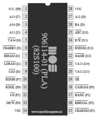

Pinout
Reference signals
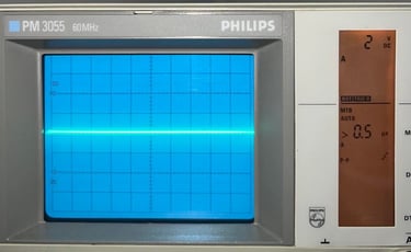
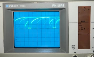
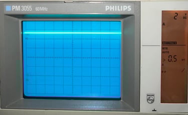
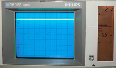
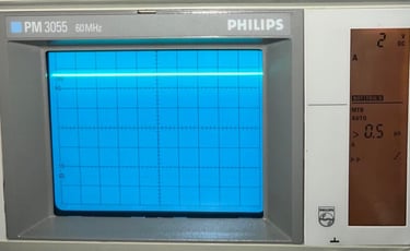
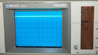
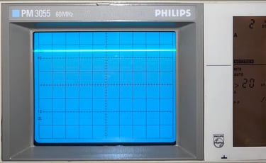
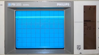
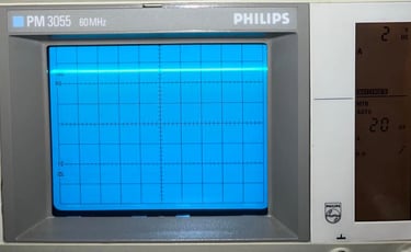
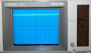
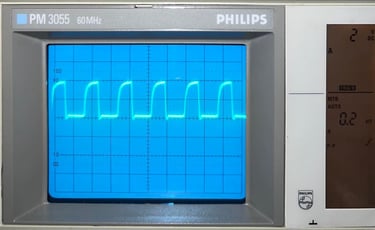
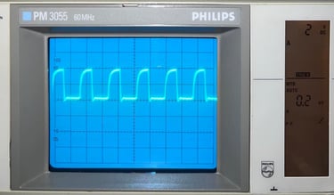
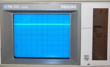
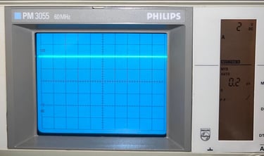
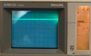
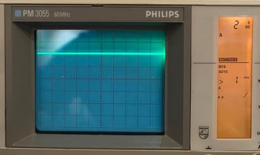
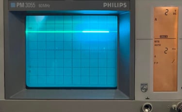
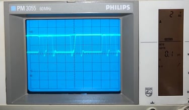
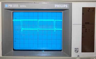
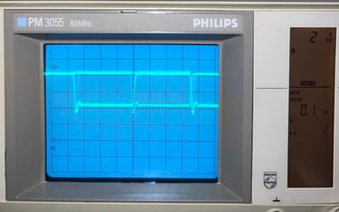
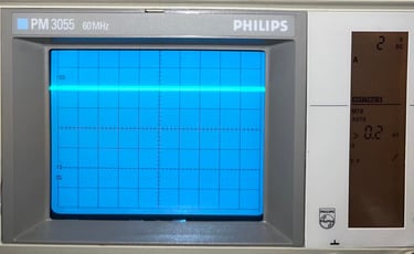
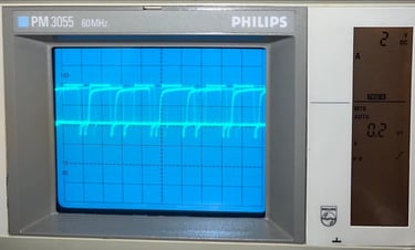
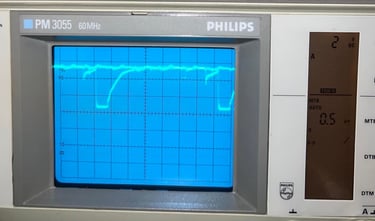
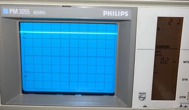
Below are simple pictures of the different signals on the PLA MOS 906114-01 chip which I use for reference/comparison during fault finding. For further details about the signals on the different C64 custom chips I will highly recommend Sven´s techsite.
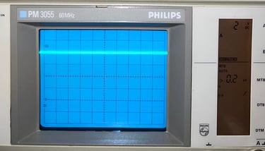
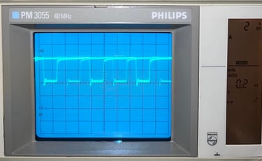
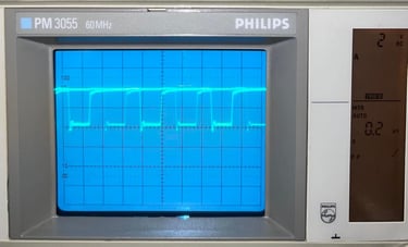
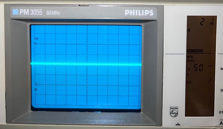
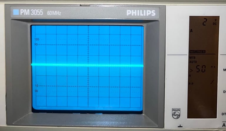
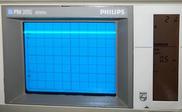
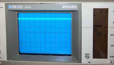
Settings on Philips/Fluke PM3055 60 MHz analog oscilloscope:
2 V / DIV
See individual pictures for time settings
Signals have been measured on a working Commodore 64 assy 250466 in idle mode (blue screen).
Pin #1
N.C.
Pin #2
A13
Connected to A13 of the address bus
Pin #3
A14
Connected to A14 of the address bus
Pin #4
A15
Connected to A15 of the address bus
Pin #5
VA14
Connected to #VA14 on VIC-II
Used for programming field-programmable parts and not connected internally for mask programmable parts
Pin #6
CHAREN
Connected to #CHAREN on I/O port of the 6510 CPU
Pin #7
HIRAM
Connected to #HIRAM on I/O port of the 6510 CPU
Pin #8
LORAM
Connected to #LORAM on I/O port of the 6510 CPU
Pin #9
CAS
Connected to #CAS on the VIC-II
Pin #10
ROMH
#ROMH
Pin #11
ROML
#ROML
Pin #12
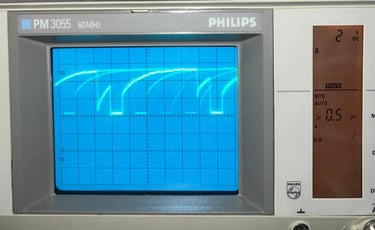
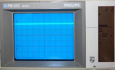
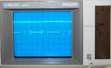
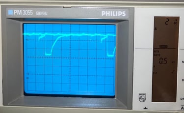
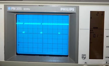
I/O
#I/O
Not so easy to see but the signal is pulled low for a very short period regularly.
Video capture of signal here
Pin #13
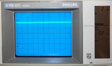
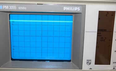
GR/W
GR/#W, connected to #WE on the color RAM
This signal is pulled low for a very short period regularly - quite the same way as pin #12.
Pin #14
VSS
Ground (GND)
Pin #15
CHARROM
Connected to #CS1 on the #CHARROM
Pin #16
KERNAL
Connected to #CS on the #KERNAL ROM
Pin #17
BASIC
Connected to #CS on the #BASIC ROM
Pin #18
CASRAM
Connected to the #CAS pin on the DRAM
Pin #19
CE
Chip Enable
Pin #20
VA12
Connected to VA12 on VIC-II
Pin #21
VA13
Connected to VA13 on VIC-II
Pin #22
GAME
Connected to #GAME on pin 8 of cartridge port
Pin #23
EXROM
Connected #EXROM on pin 9 of cartridge port
Pin #24
R/W
Connected to R/#W of the bus
Pin #25
AEC
#AEC, connected to inverted version of AEC on the VIC-II
Pin #26
BA
Connected to BA on the VIC-II
Pin #27
A12
Connected to A12 of the address bus
Pin #28
VCC
+5V
Banner picture credits: Xato