
Prof Competition 9000 de luxe
Starting point
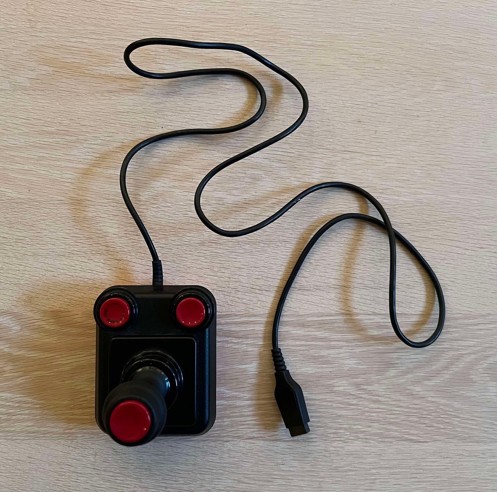
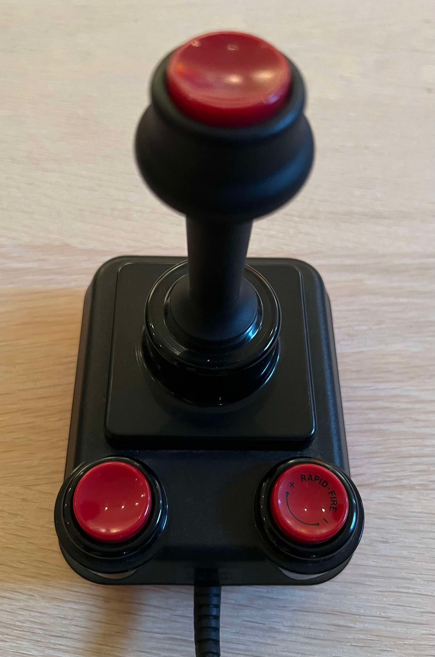
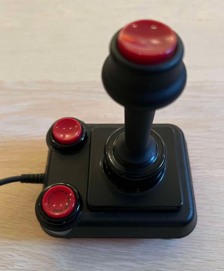
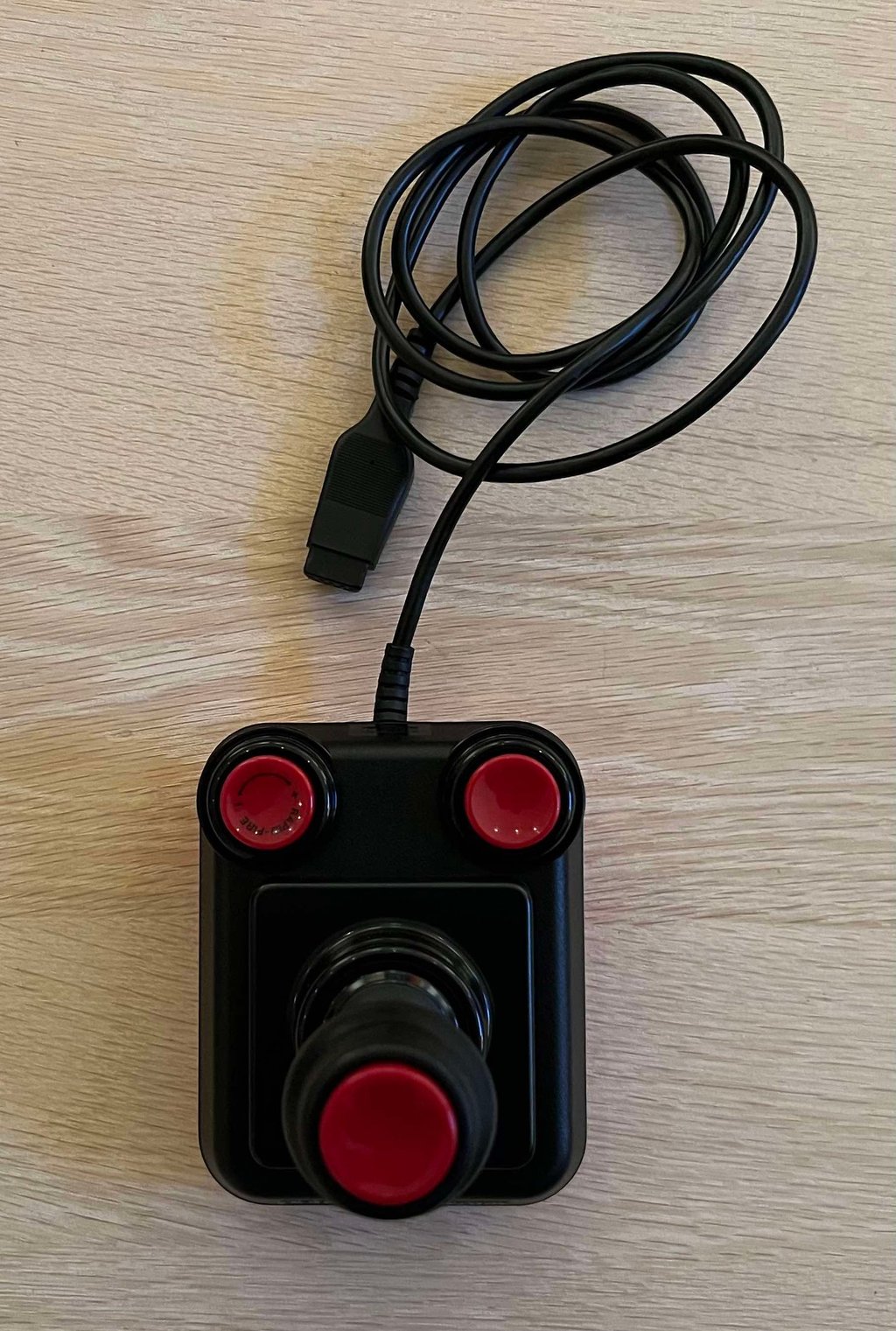
Suzo´s flagship: the Prof Competition 9000 de luxe. Equipped with three fire buttons, and an adjustable auto fire, this was the most sophisticated joystick from the dutch compamy Suzo International.
But this otherwise fine looking joystick has a problem: the auto fire (aka "Rapid-fire") does not work. Or to be more precise, the auto fire function do work but it is not possible to adjust the fire-rate or disable it. The auto fire is always on...
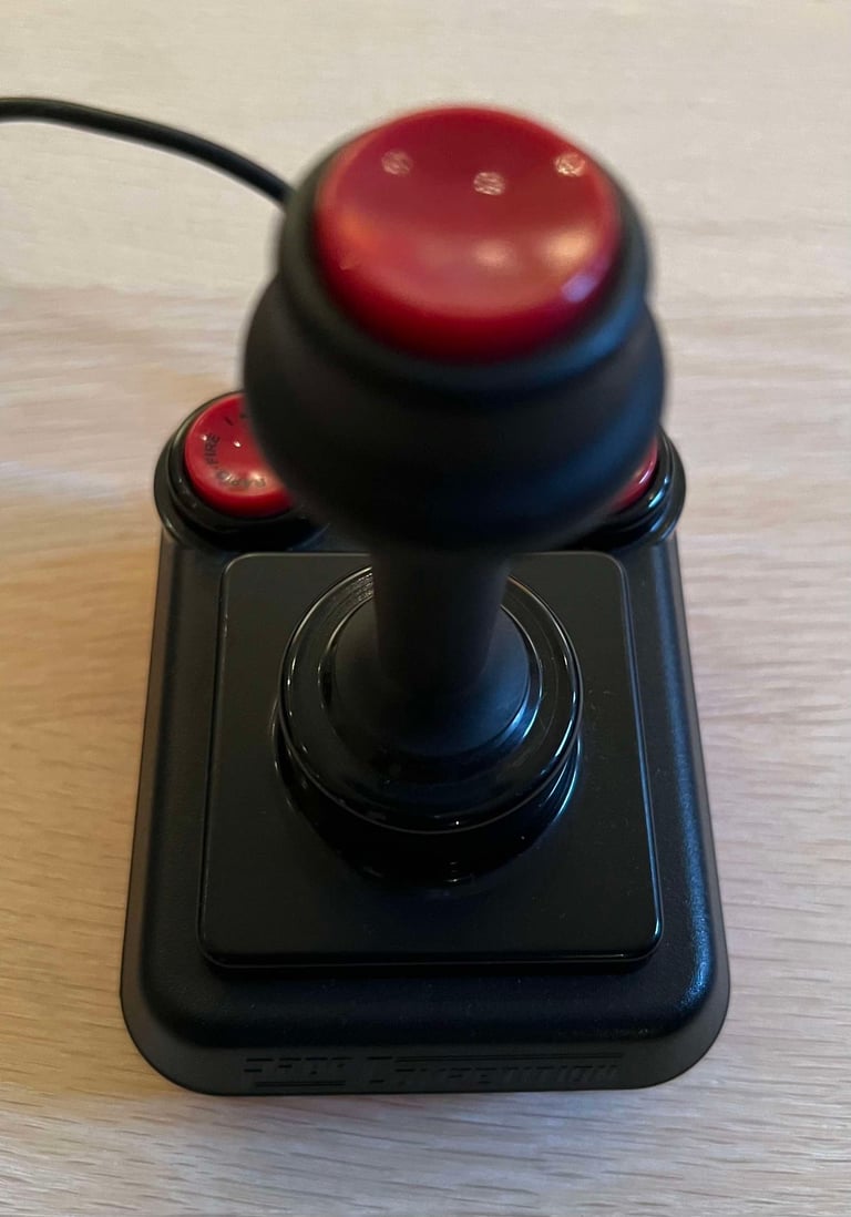
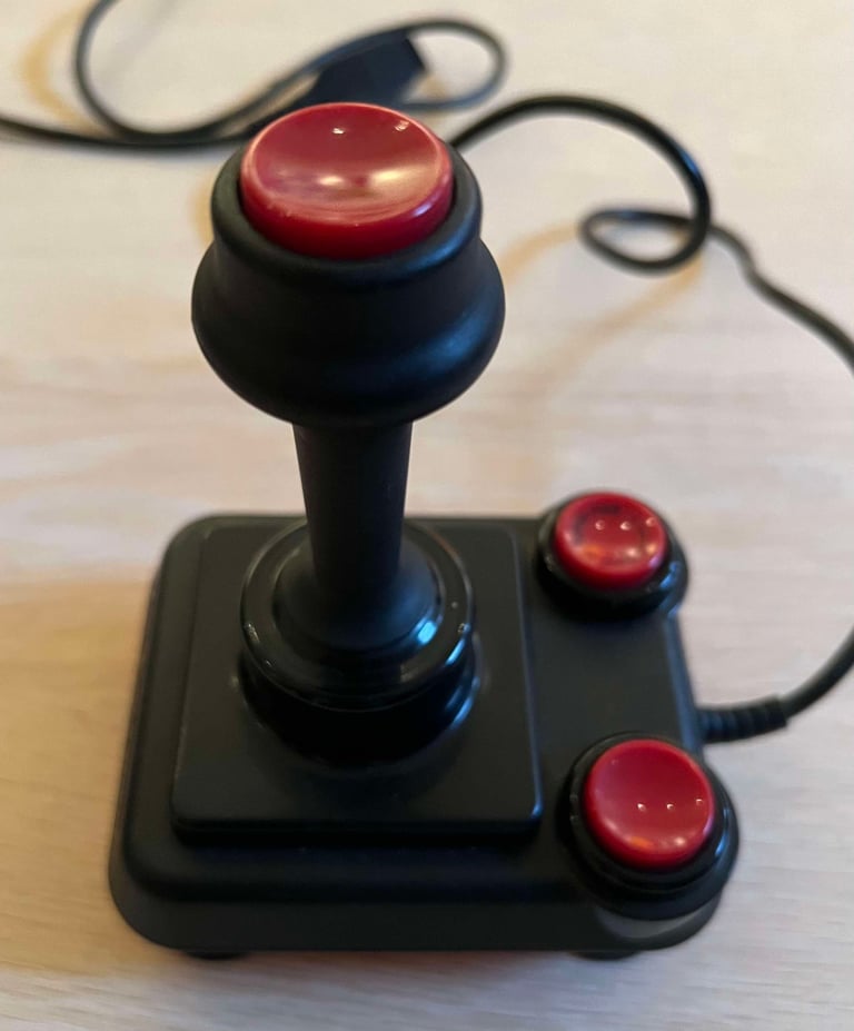
The exterior has some dust and grease, but it is marginal and looks superficial. And the sound of the four microswitches used for the UP/DOWN/LEFT/RIGHT direction sound as they should - the trusty good "click" sound is in place. As mentioned the auto fire does not work, but the fire buttons (all three of them) do seem to mechanical ok. So there is something wrong inside the joystick...
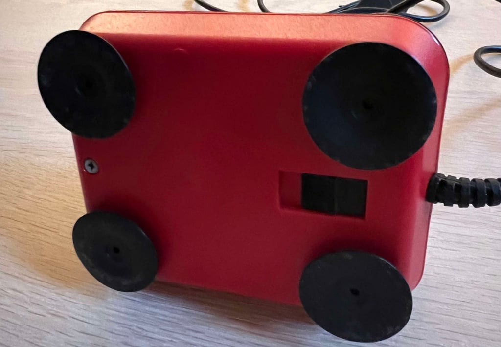
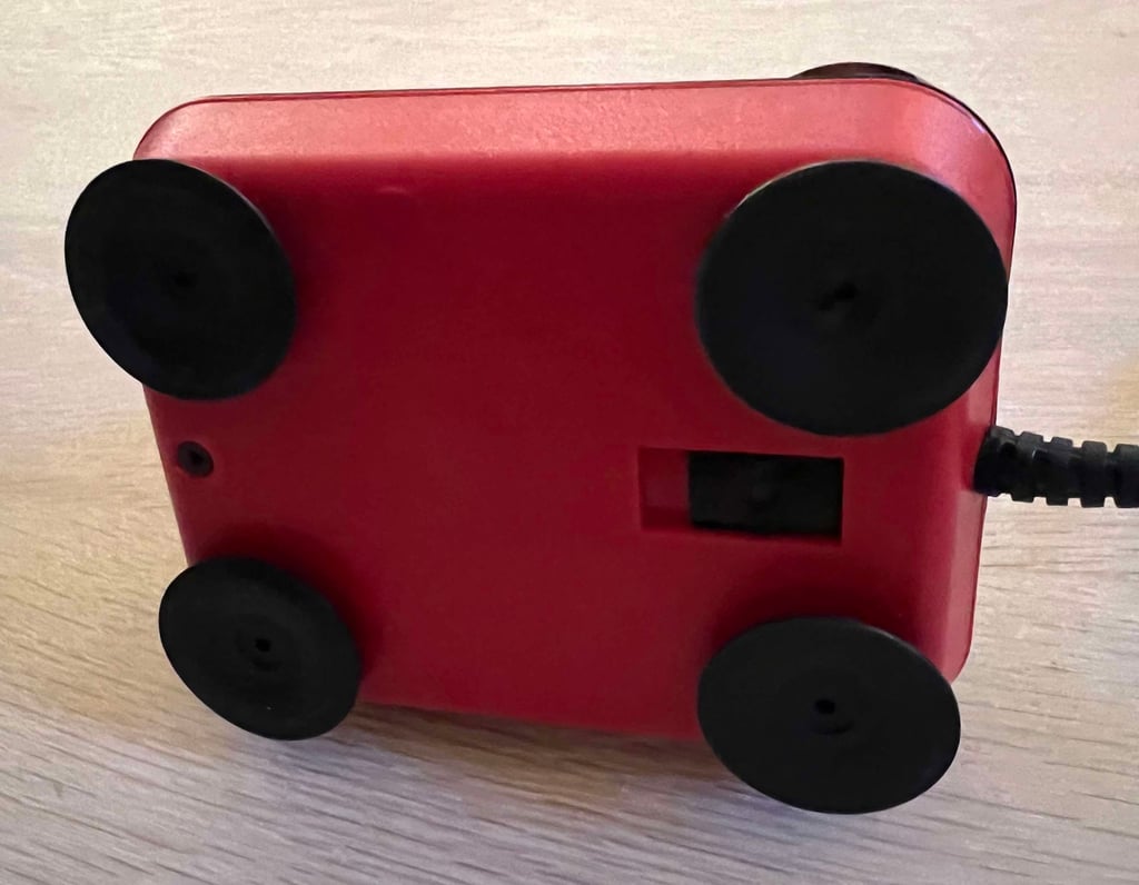
At the bottom the switch used to toggle between which fire button to use (SHAFT/BASE) seems to be ok. It is a bit stiff, but this is probably ok. Some lubrication might be required.
All the four rubber feet are in place. They are a bit dirty, but I think that is to be expected after 30+ years. Even the three screws are in place, so maybe no one has opened this joystick since it was assembled. The cable and connector also seem to be in fine condition.
Below are some pictures of the joystick before the refurbishement.






Refurbishment plan
To refurbish this Competition Pro joystick the plan is to do this by:
Cleaning the exterior casing
Check (and potentially repair) the interior electronics, auto fire, switches and mechanics
Check cable and check cable connectivity
Verify operation by testing
Disassembly
With any luck this disassembly will be easy. If I can refurbish this joystick by just disassembling the top- and bottom cover I reduce the risk of damaging the plastic parts. It is possible to disassemble almost all parts of the joystick, but there is a risk of damaging (or making marks on) the parts.
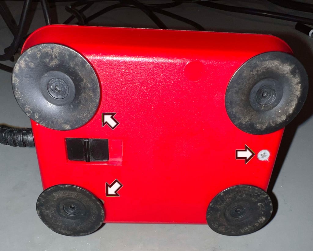
First the three screws at the bottom are removed. These screws have the dimension of 3 mm x 20 mm (conical - from tip to toe). Note that the screws are hidden beneath the rubber feet.

The top cover is lifted from the bottom and the interior is revealed. First impression is very good. There are some dust and grease, but not more than expected after so many years. Unfortunately (?), I can not see anything immediate which would cause the auto fire to malfunction (that is being constantly turned on).
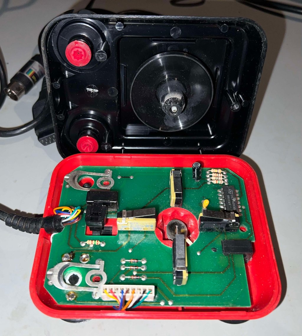

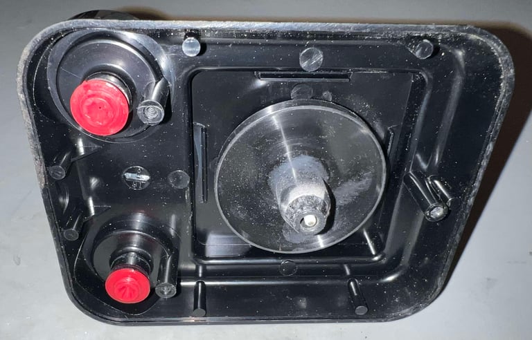
Now the PCB is lifted away from the bottom cover. And this is where the disassembly stop for now. Unless it is required for disassemble the fire buttons and/or the shaft for any repair, it is best to stop here to avoid risking any damage to the parts.
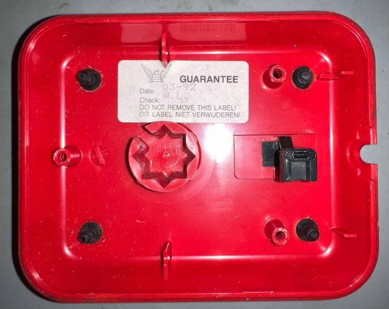
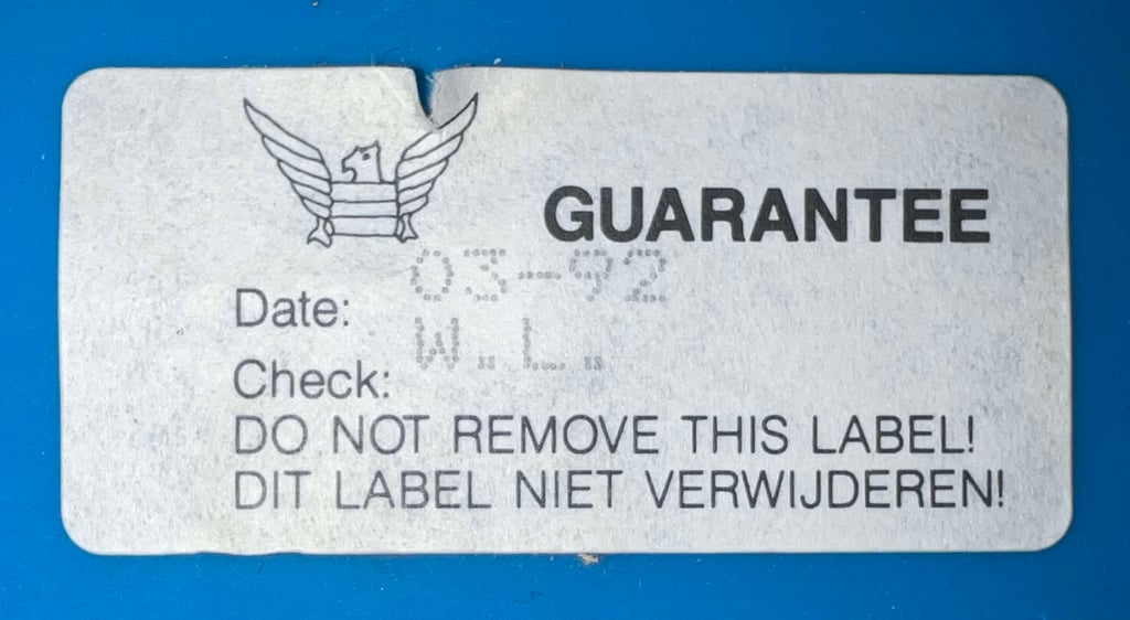
Notice the sticker on the bottom cover which says "Date: 03-92 / Check: W.L.". How cool is that? A sticker saying that "W.L." checked this joystick after assembly in March 1992. Perhaps listening to Nirvana playing "Smells like teen spirit" on the Sony discman?


Exterior casing and plastic parts
Before soaking the plastic parts in water the warranty sticker is removed. This is done by applying some hot air from a hair dryer while carefully peeling the sticker off with a pair of tweezers. The sticker is removed without any damage (note that the small rip in the top was from factory).

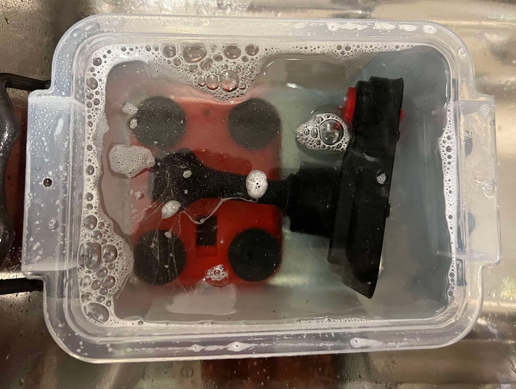
With the sticker out of the way the parts are placed in a box filled with mild soap water for abour 24 hours.

Electronics and microswitches
The PCBs used in the Suzo range of joysticks are really nice. Not that the quality of the PCB itself is superior to other joystick PCBs, but the Suzo joysticks always have PCB which are tidy and "minimalistic". And this PCB is not an exception. All components are placed in a tidy and clever manner, IC is used in stead of transistor/resistor network and a cable connector is used instead of soldering directly to the PCB. Nice!
There are some dust and grease on the PCB. But not much. The backside of the PCB is covered with flux residue, but that should be easy to get rid of.
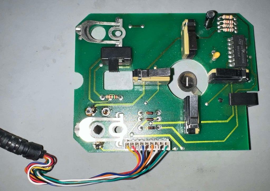

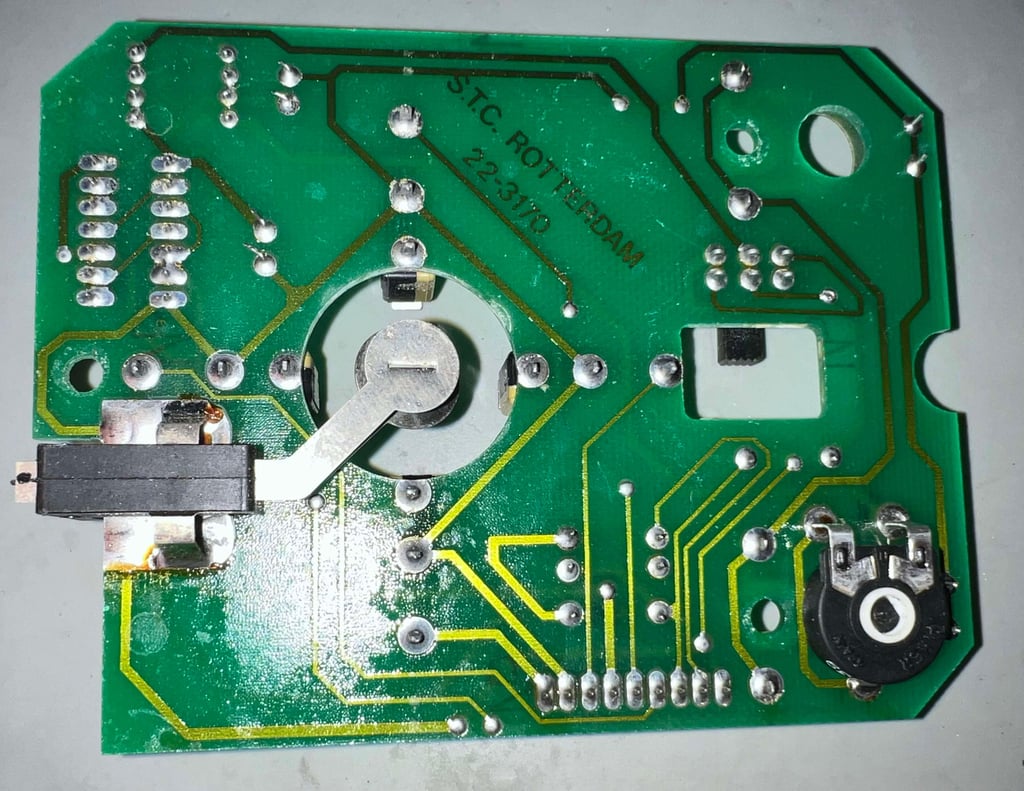

The PCB is marked "S.T.C. Rotterdam" which is an abbreviation for "Suzo Trading Corporation Rotterdam". In addition the PCB is marked with "22-3170" which would identify the revision of the PCB.
Visual inspection
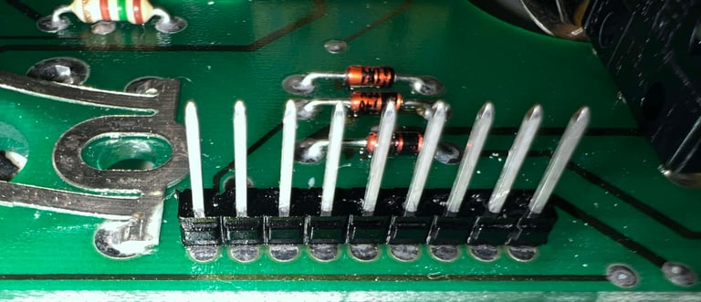
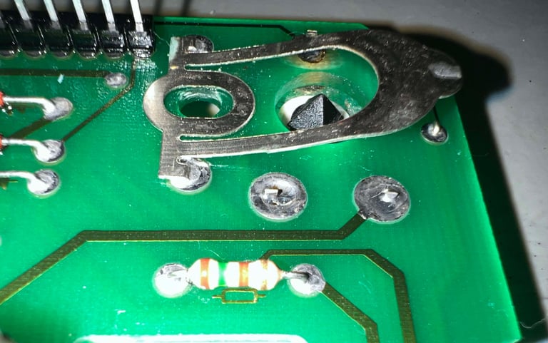
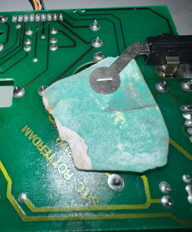
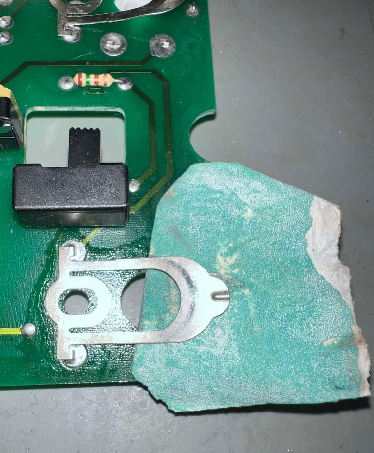
As mentioned there are some flux residue on the backside of the PCB. But this should not affect the performance, or functions such as the auto fire, in any way. But there are some areas which require attention (see pictures below):
The cable pin head connector is oxidized (or at least covered with something)
The small metal staples beneath the base fire buttons are a bit dark (oxidation?)
Some of the larger solder points are very dark. I assume this is some old flux residue
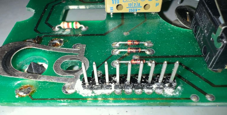

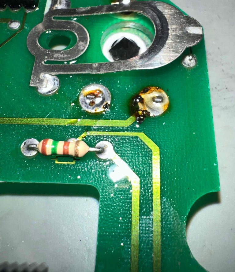

I do not think that these issues would be related to the problem with auto fire. Nevertheless, all these areas are carefully checked and cleaned. See pictures below.




Identifying the auto fire fault?
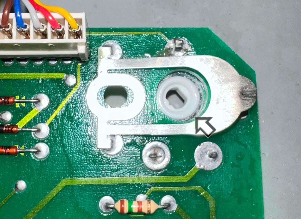
The auto fire, which is currently constantly active, is controlled by a variable resistance potentiometer. This allows for the rate the auto fire is "fired" can be user controlled: from zero rate to full rate.
In the middle of the potentiometer is a small plastic "diamond" shape part. This small plastic part will engage to the shaft of the left fire button. The small part is lifted from the potentiometer with a pair of tweezers.
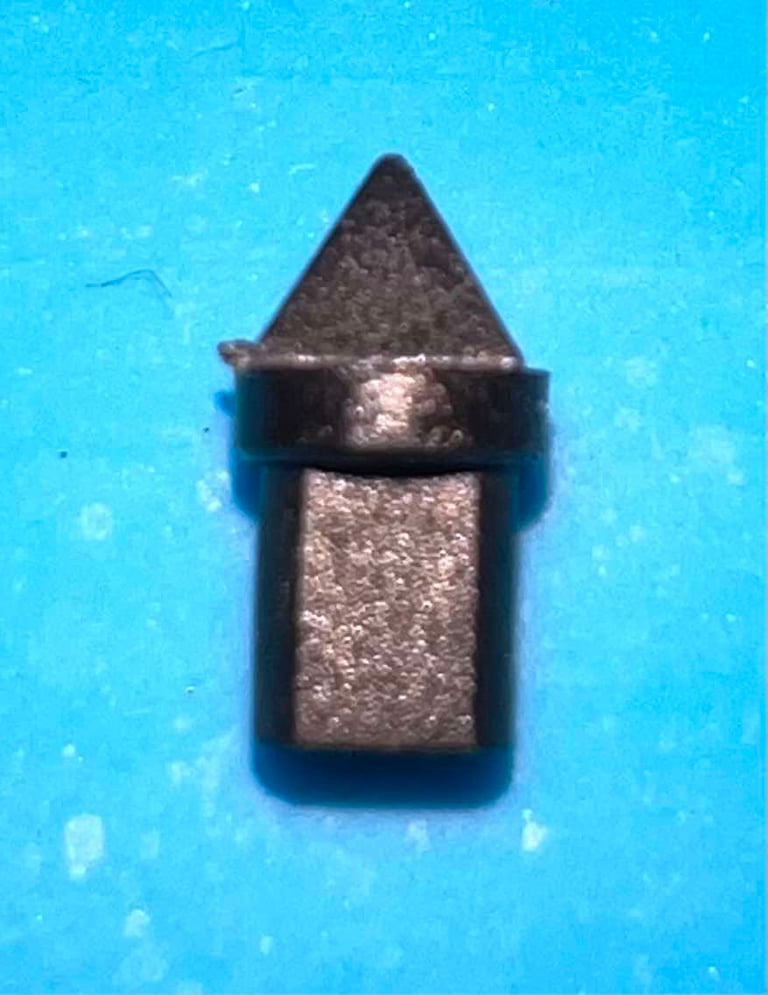

It seems like the potentiometer is a bit "stuck". It is able to turn, but the friction appear to be higher than normal. Could this be the problem? That the potentiometer does not turn properly?
Some (plenty) of contact cleaner is applied to the interior of the potentiometer. With a pair of tweezers the potentiometer is turned back and forth several times to make sure that the contact cleaner reach the inside. This seems to reduce the friction substantially. With any luck this will solve the problem! Fingers crossed!
Below is a picture of the potentiometer (from above) and the plastic part removed.

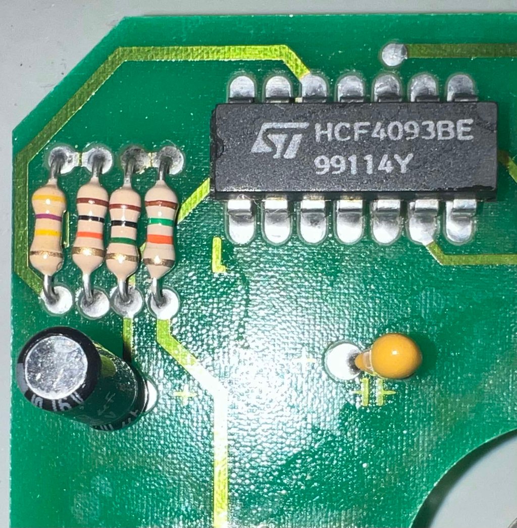
The PCB is equipped with a HCF4093BE (ST) quad 2-input NAND Schmitt trigger. This IC is used in combination with a 10 uF [16V] electrolytic capacitor, a tantalum capacitor and resistor network. Since the auto fire is "firing" I do not think there is any issues with this circuitry.

Cleaning the microswitches and toggle switch
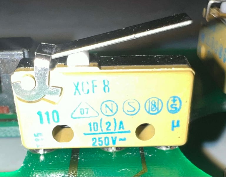
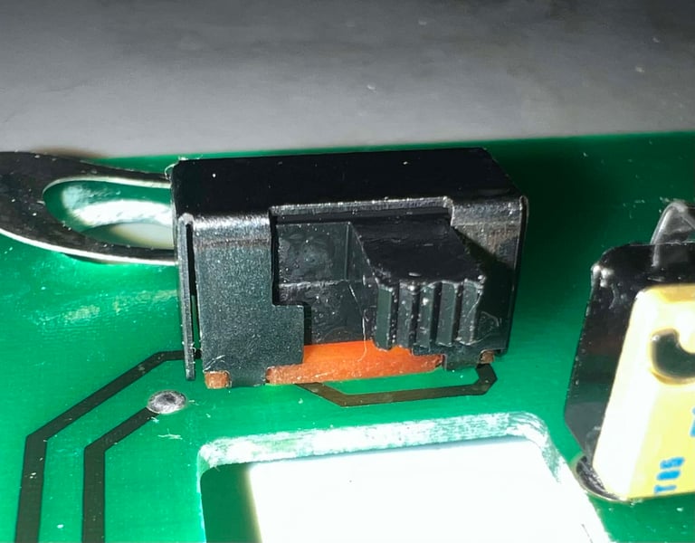
There are four microswitches from Landis & Gyr / SAIA and marked "XCF8". Notice that these microswitches are "micro" in the right sense. Compared to other microswitches found in joysticks such as Zipstik and Competition Pro the microswitches in these Suzo joystick measures only 20 x 6.5 x 10 mm (casing size). Each of the microswitches are sprayed with contact cleaner and "massaged" by pushing the lever down repeatedly.
Also, there is a toggle switch which select between the base fire button(s) and the shaft fire button. This switch is also cleaned properly with contact cleaner and "massaged" by moving the switch back and forth.


Checking connectivity
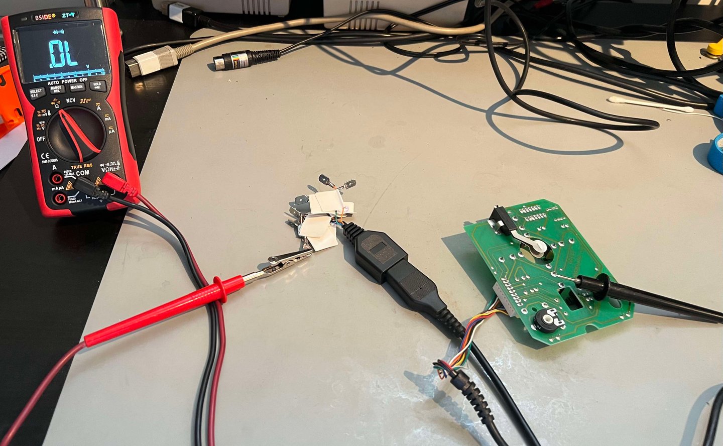
The cable is checked for connectivity end-to-end. A dummy male DB9 connector is used together with a multimeter in diode/continuity mode. All of the nine wires within the cable is measured to be ok.

Testing
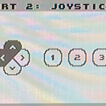
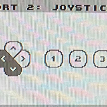
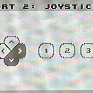
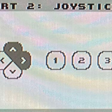
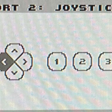
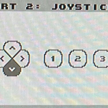
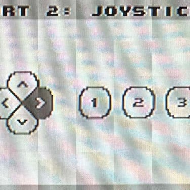
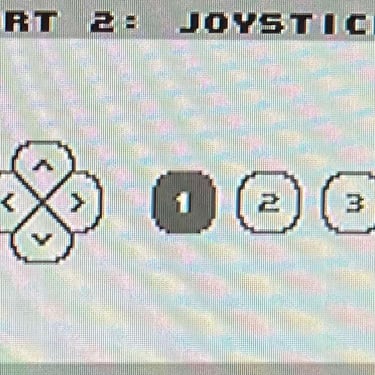
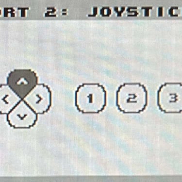
To verify that the joystick work as it should I check it with the Joyride software. Result is that all directions and fire buttons works fine works as expected (click to enlarge). All tests pass.
NOTE: The auto fire (aka rapid fire) works as it should now. You can adjust the rate from 0 (normal fire) to full speed (auto fire). But to adjust the rate it is a bit user-unfriendly. Left side fire button needs to be pushed, and locked back/forth to "lock" to the potentiometer, and then twisted towards the right or left. But it is not so easy to get a good grip for doing this. Nevertheless, it does work as it should - the user experience is something that was forgotten some time in the 90s.
Final result
"A picture worth a thousand words"
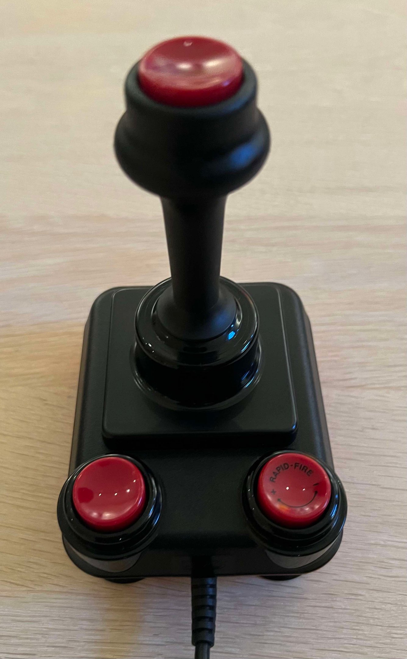
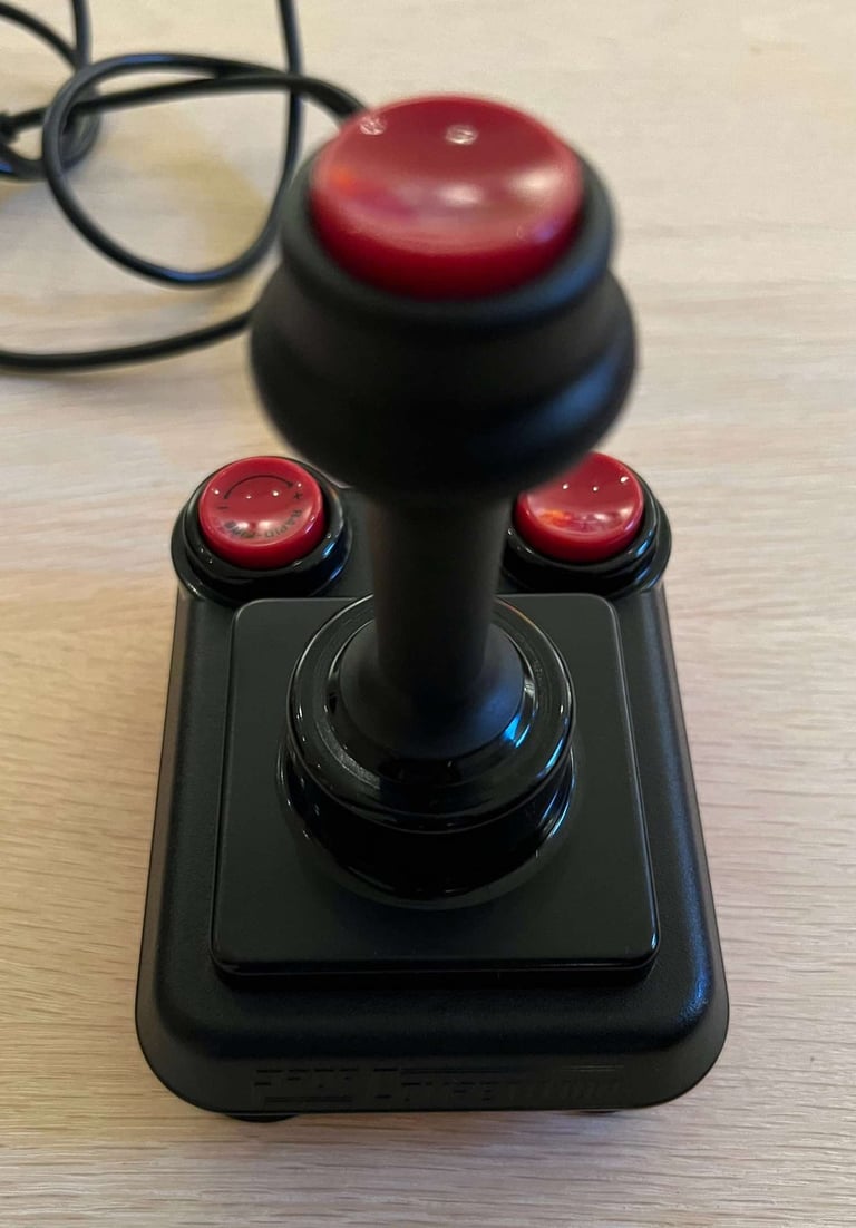
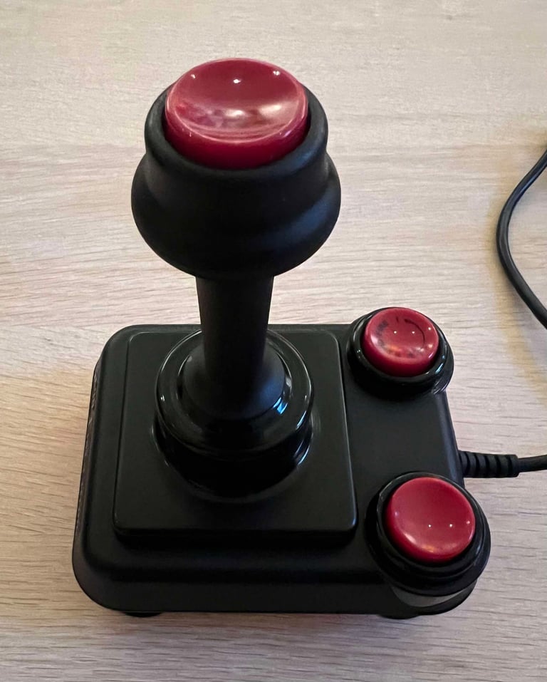
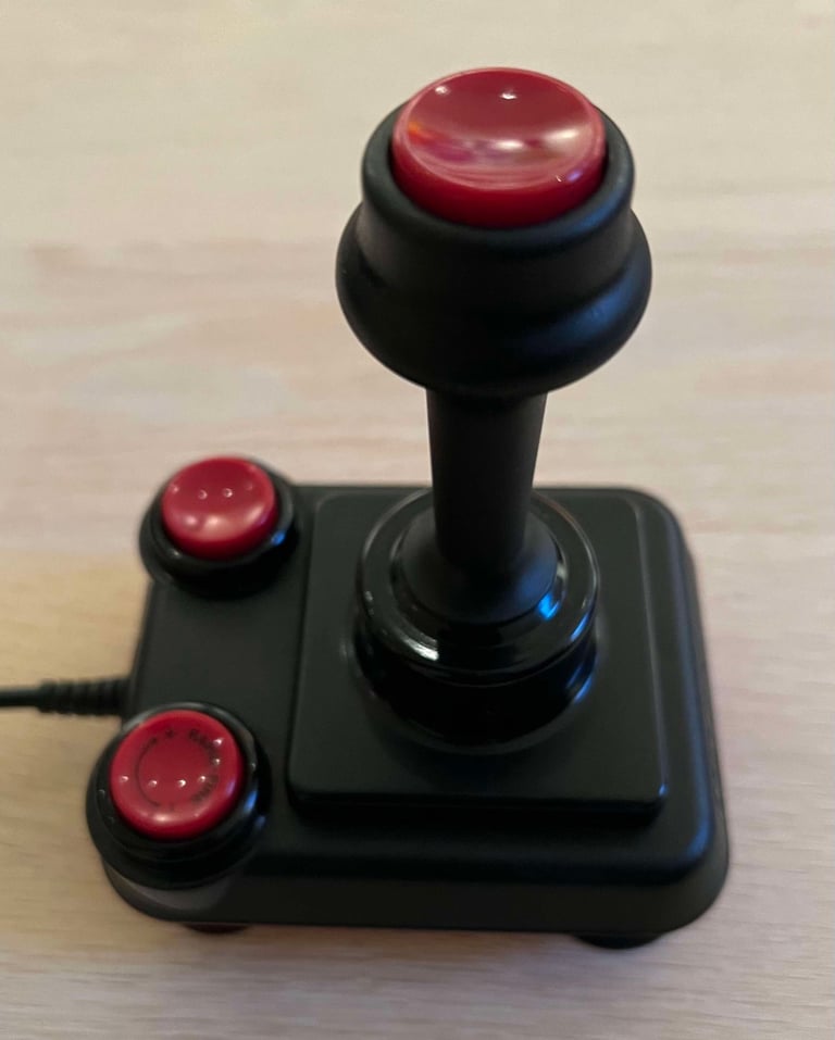
Below is a collection of the final result from the refurbishment of this Prof Competition 9000 de luxe joystick. Hope you like it! Click to enlarge!






Banner picture credits: Kshade
