

QuickJoy 120
Starting point
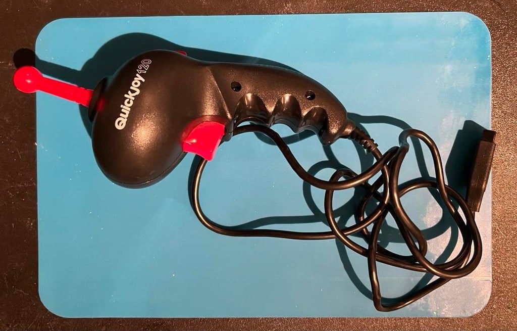
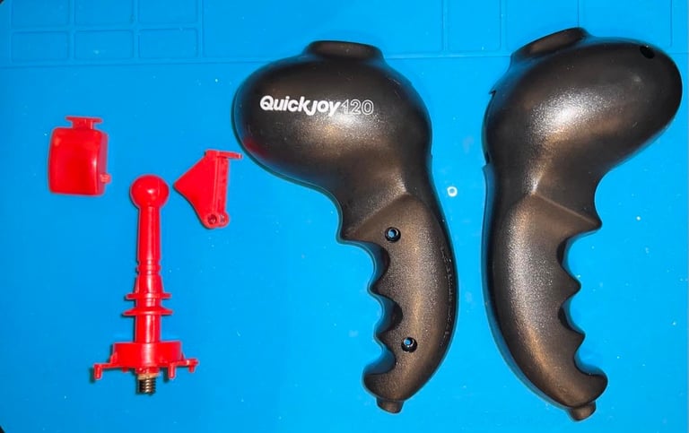
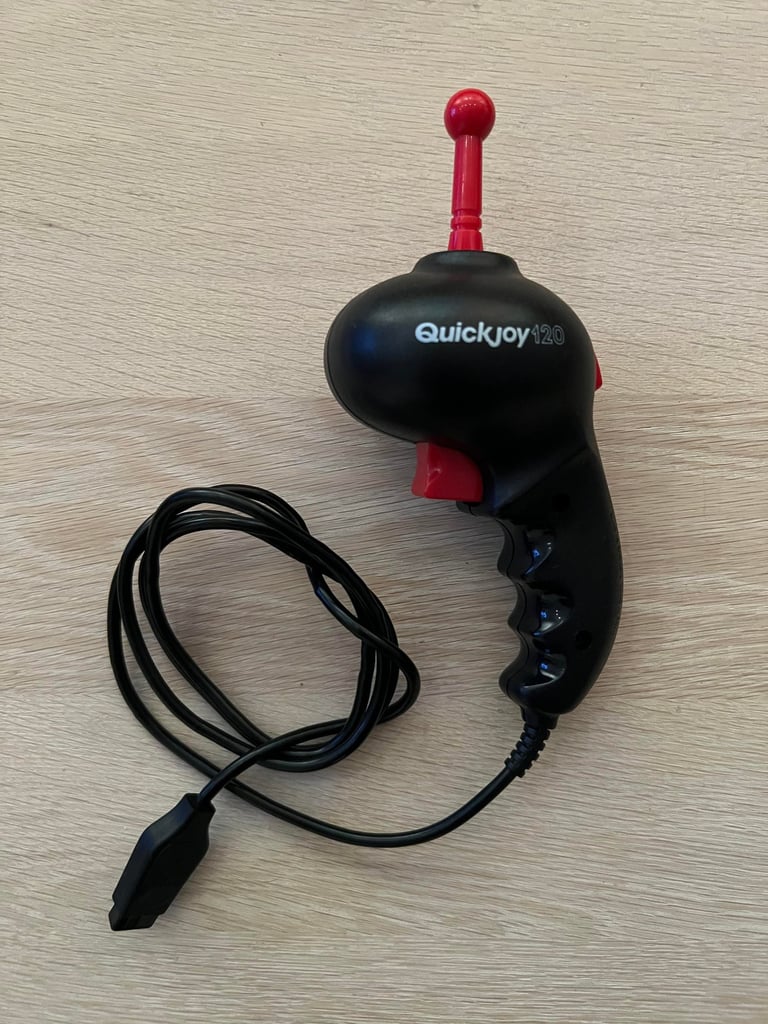
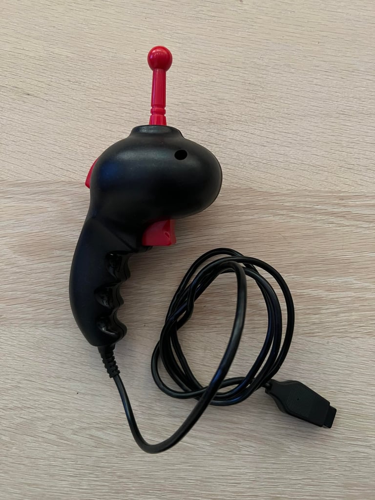
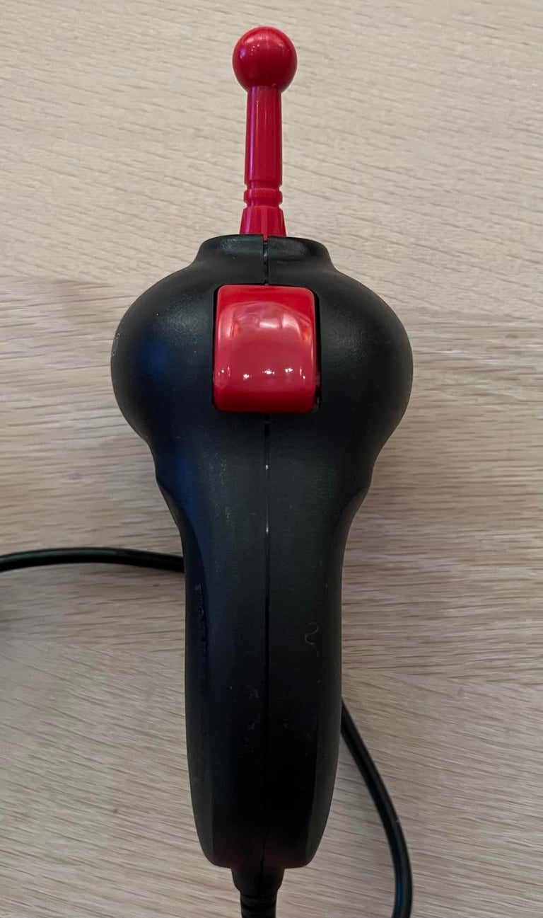
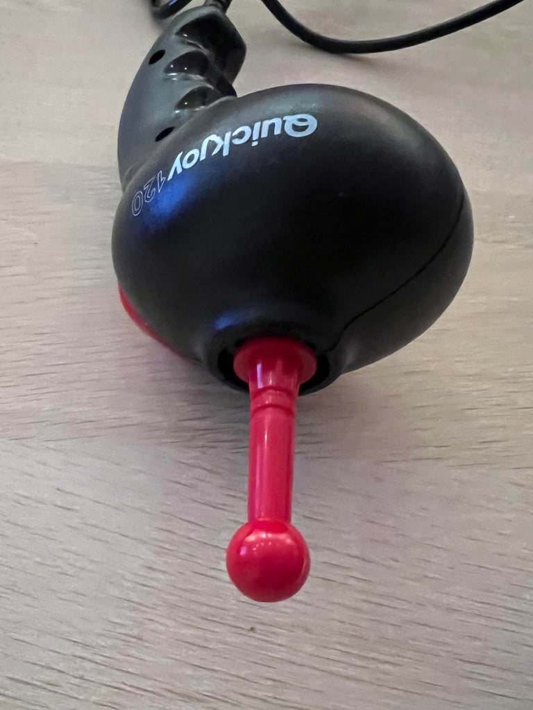
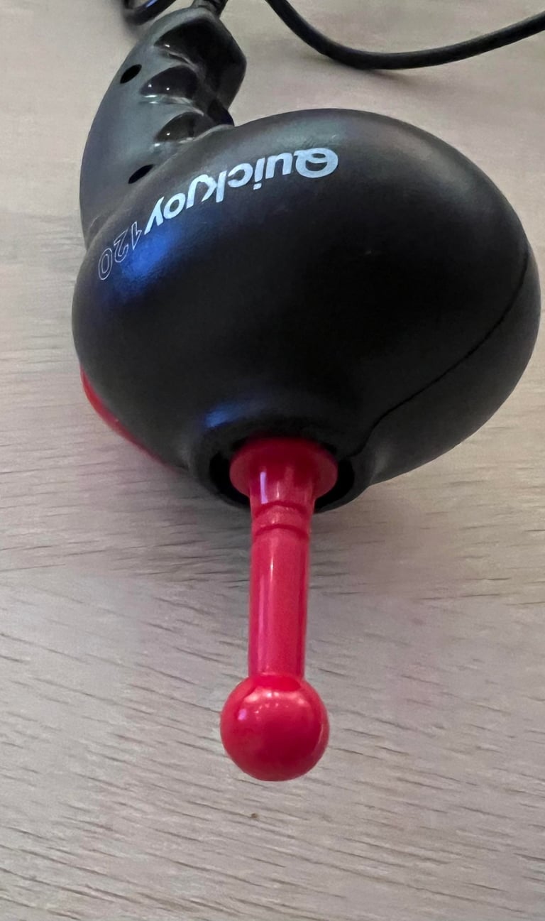
A bit different looking joystick than the normal "80s" joystick. Nevertheless, from the outside it looks to be a well made quality joystick for the Commodore or Atari. The picture below doesn´t show it well, but there is a lot of sticky grease around the bottom of the red shaft. Besides from that the joystick appears to be undamaged and well taken care of.
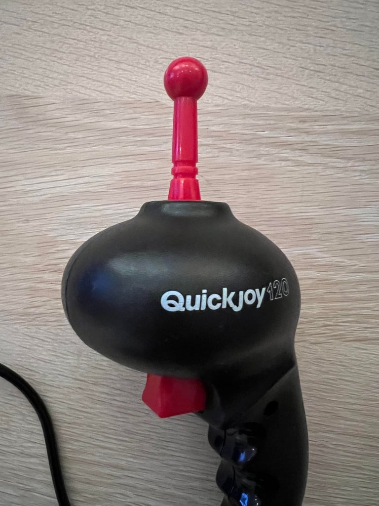
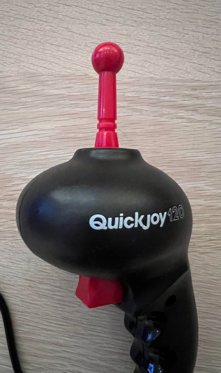
It is branded with "Quickjoy 120", but I´m not sure who has manufactured this one. Spectravideo?

Refurbishment plan
To refurbish this joystick the plan is to do that through the following steps (some of them in parallell):
Clean the exterior chassis
Check and clean interior electronics - and verify that the joystick is Commodore/Atari compliant
Check cable connectivity - replace cable if broken
Verify operation by testing
Exterior chassis
The exterior chassis looks quite nice - some nasty grease around the shaft, but otherwise undamaged. The chassis consist of a right- and left cover which are held together by three screws (two on the left and one on the right).

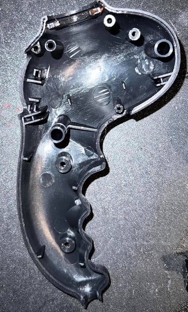
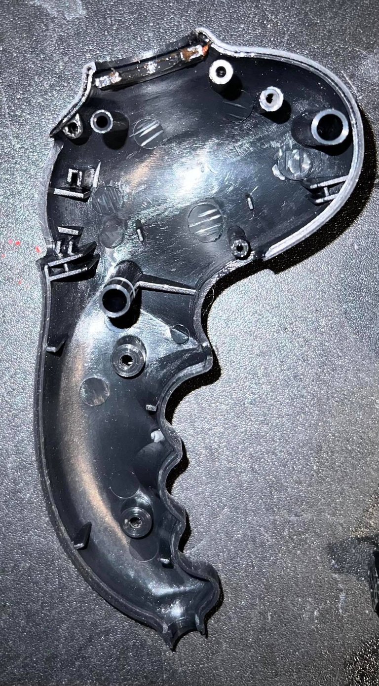
All parts are cleaned with luke warm soap water. And afterwards the same parts are cleaned with glass cleaning spray. Also, the red top shaft is sprayed (gently!) with some silicon spray just around the ring where it touches the chassis. This is just provide some lubrication for smooth operation - probably not strictly required.

Interior electronics and cable
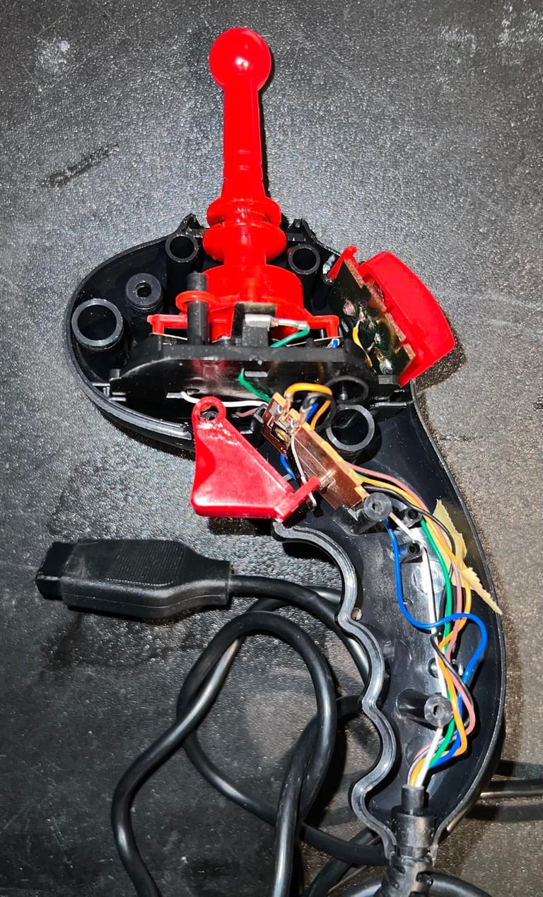
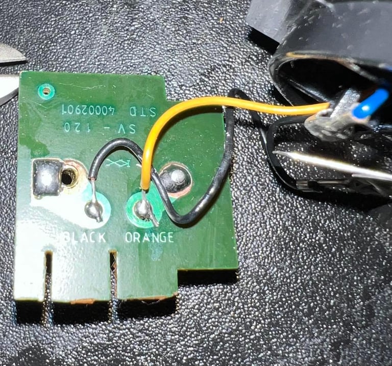
Inside the joystick there are two small PCBs. Each of these PCBs are used to detect the press of the fire buttons. There are no PCB used for the RIGHT/LEFT/UP/DOWN directions. Instead, the wires are connected directly to the four axis leaf switch.
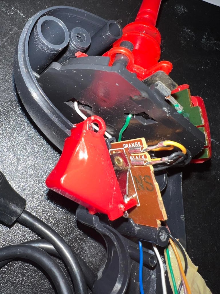

Both PCBs are thoroughly cleaned with isopropanol.
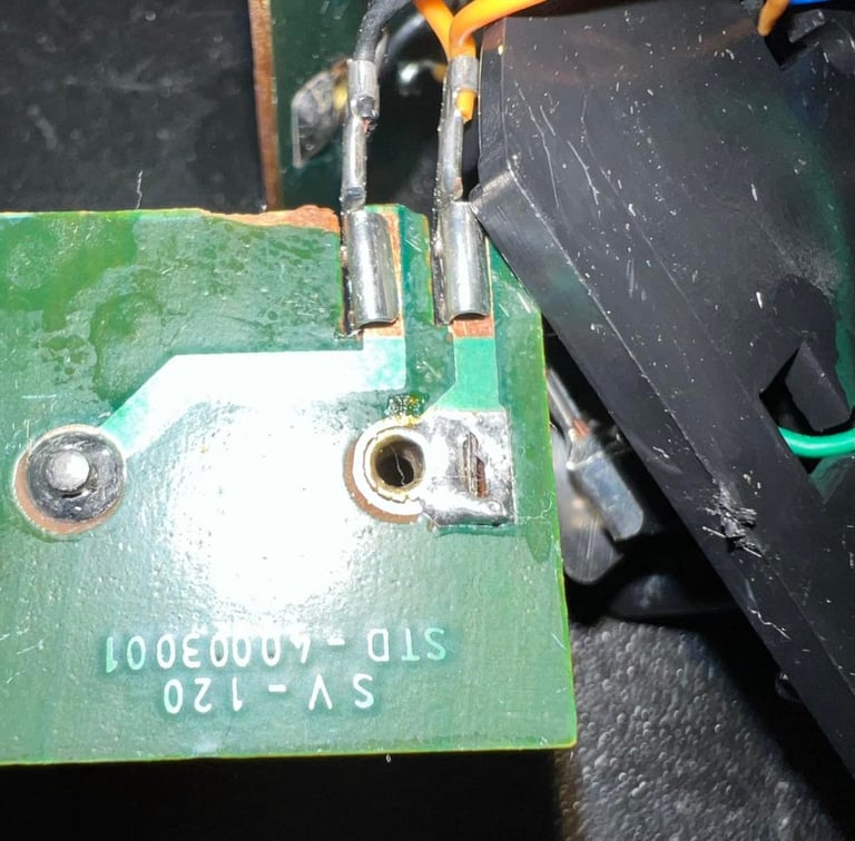
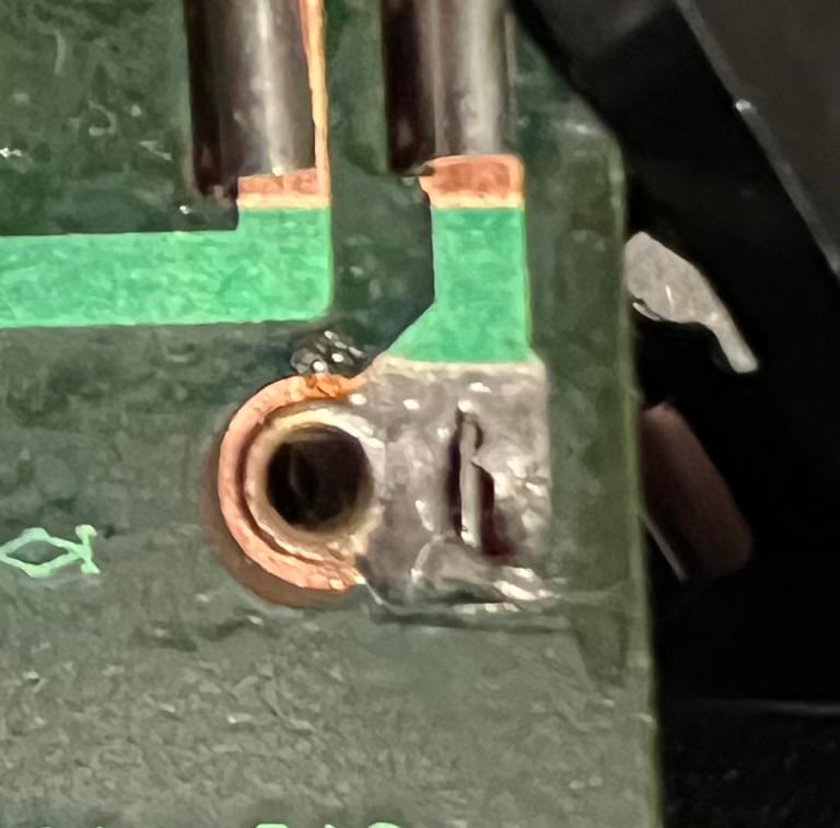
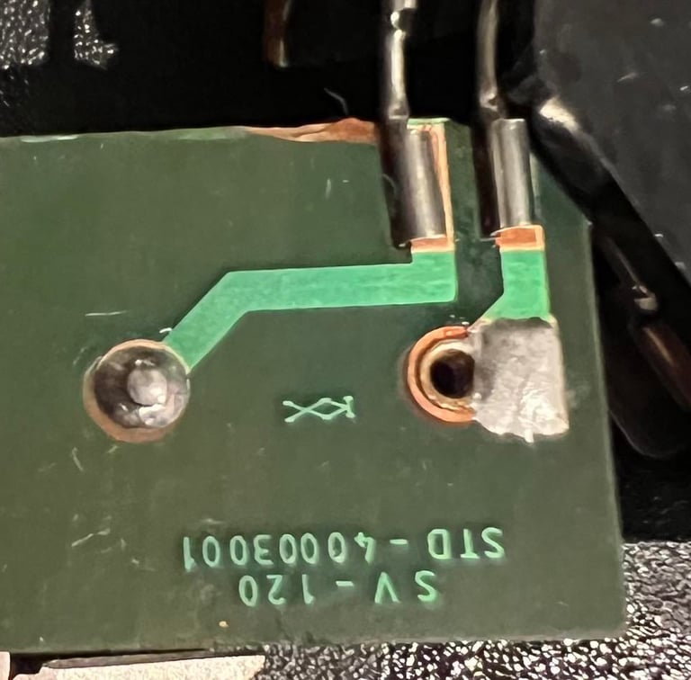
I notice that the soldering is almost gone on the front fire button. If you see the left picture above, or the left picture below, you will see that there are quite some soldering missing. The pin is visible and not covered with solder. This is repaired by resoldering the pin.


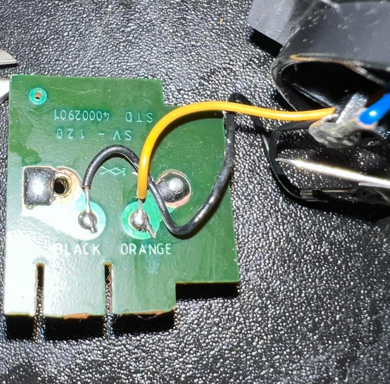
The cable and wires appear undamaged and in good condition. Connectivity is checked using the schematics shown below. Note that in this schematics the pinout is seen from the Commodore 64 side - so when checking directly on the cable connector on the joystick you need to mirror this pinout.

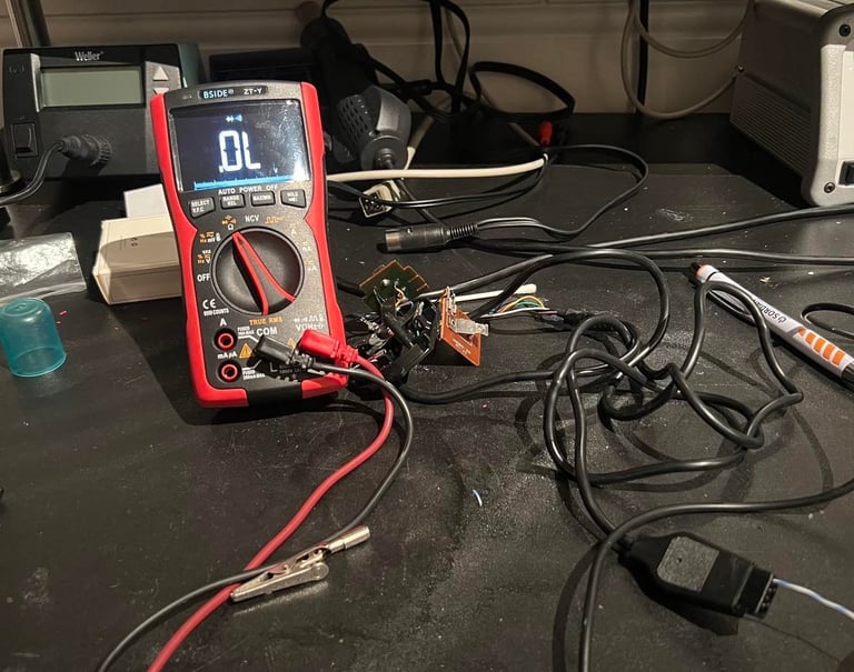
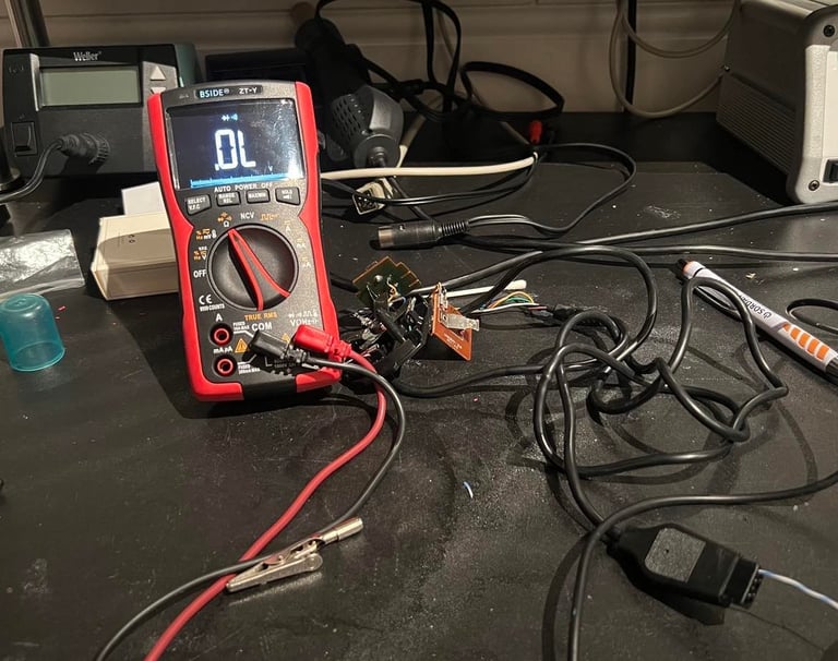
No faults are found in either the contact and the wires. I use a multimeter to check the connectivity on all wires (while twisting and turning them). There are only six wires used in this joystick: UP/DOWN/RIGHT/LEFT/FIRE/GND. The result is that all wires and connector are fine.
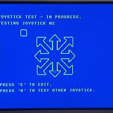
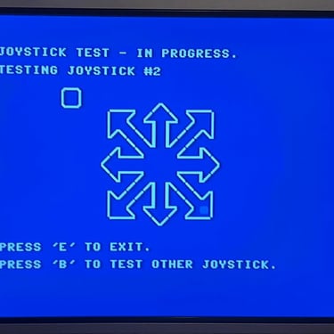
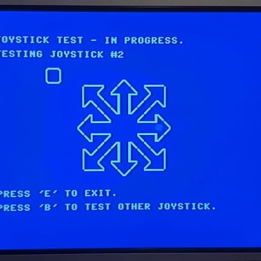
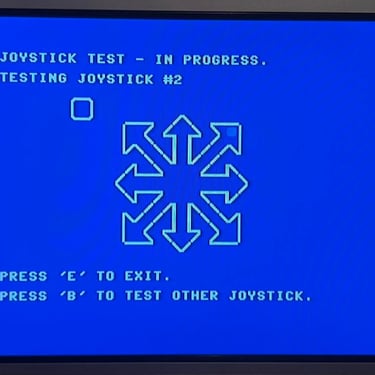
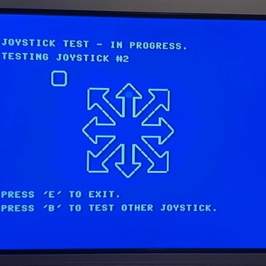
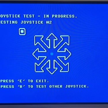
Testing
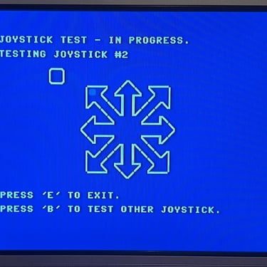
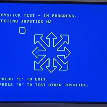
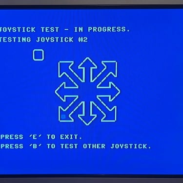
Testing is done using the joystick application in the 64 Doctor running on a Commodore 64. All directions, including combinations such as LEFT/UP simultaneously, works. And also both fire buttons works fine. See picture gallery below.
Final result
"A picture worth a thousand words"
Below is a collection of the final result from the refurbishment of this joystick. Hope you like it! Click to enlarge!

Banner picture credits: BHSPitMonkey