
Quickshot
QS-137F
Starting point
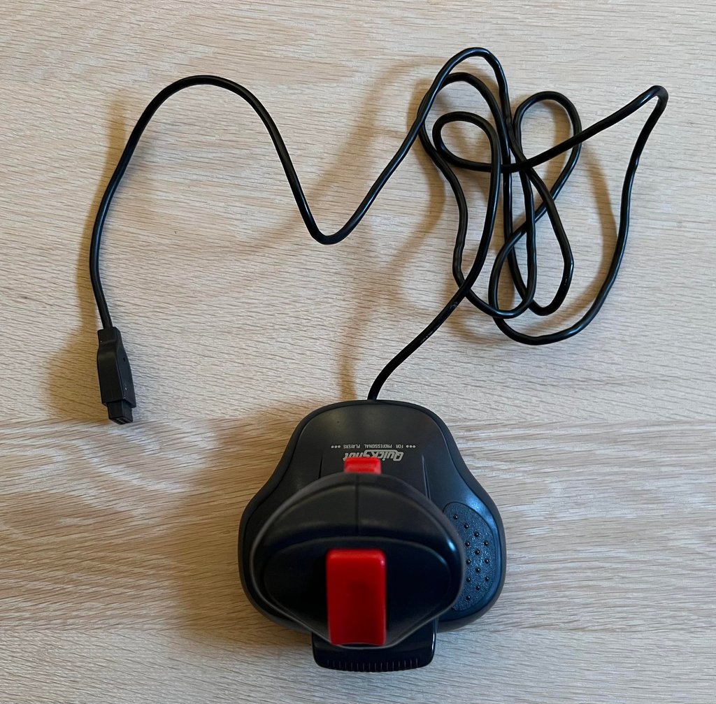
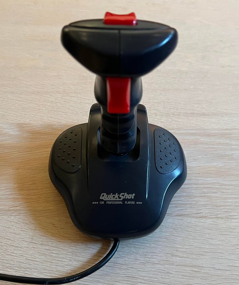
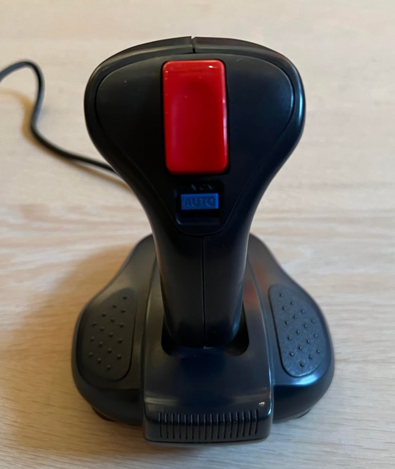
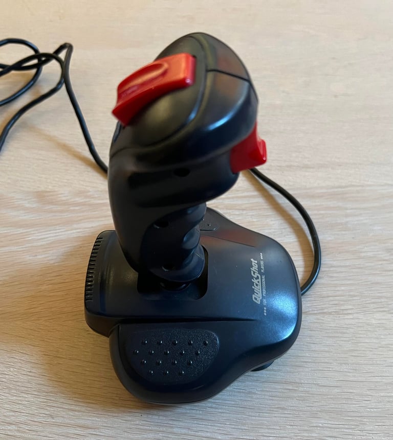
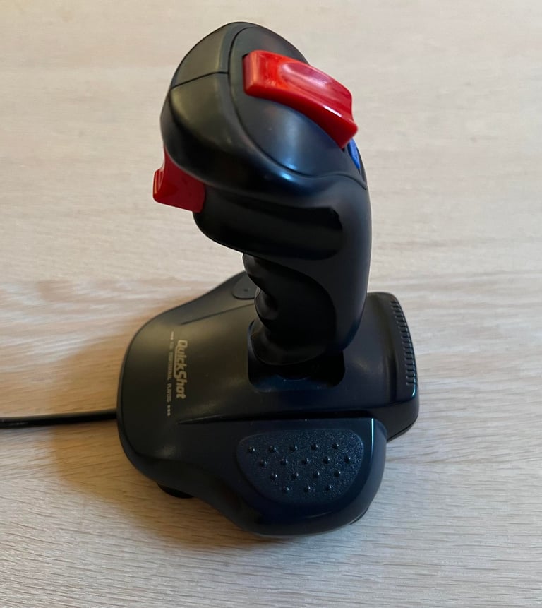
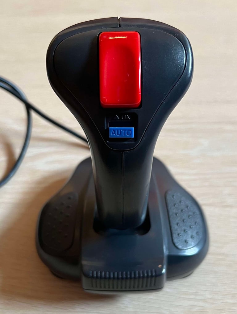
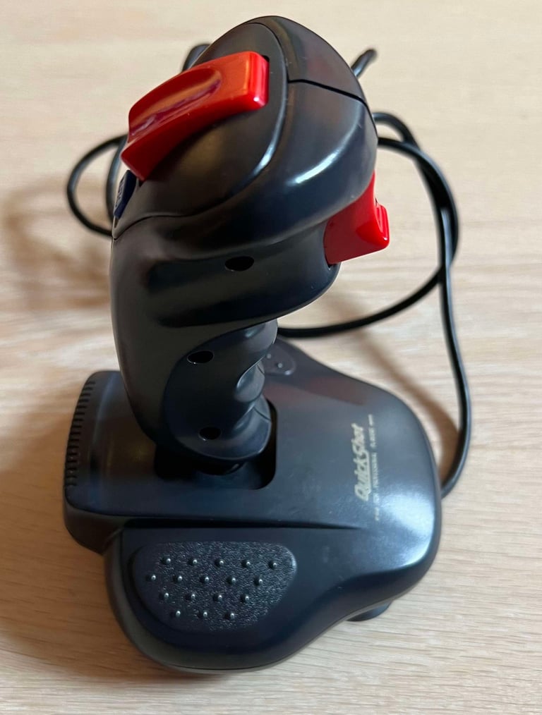
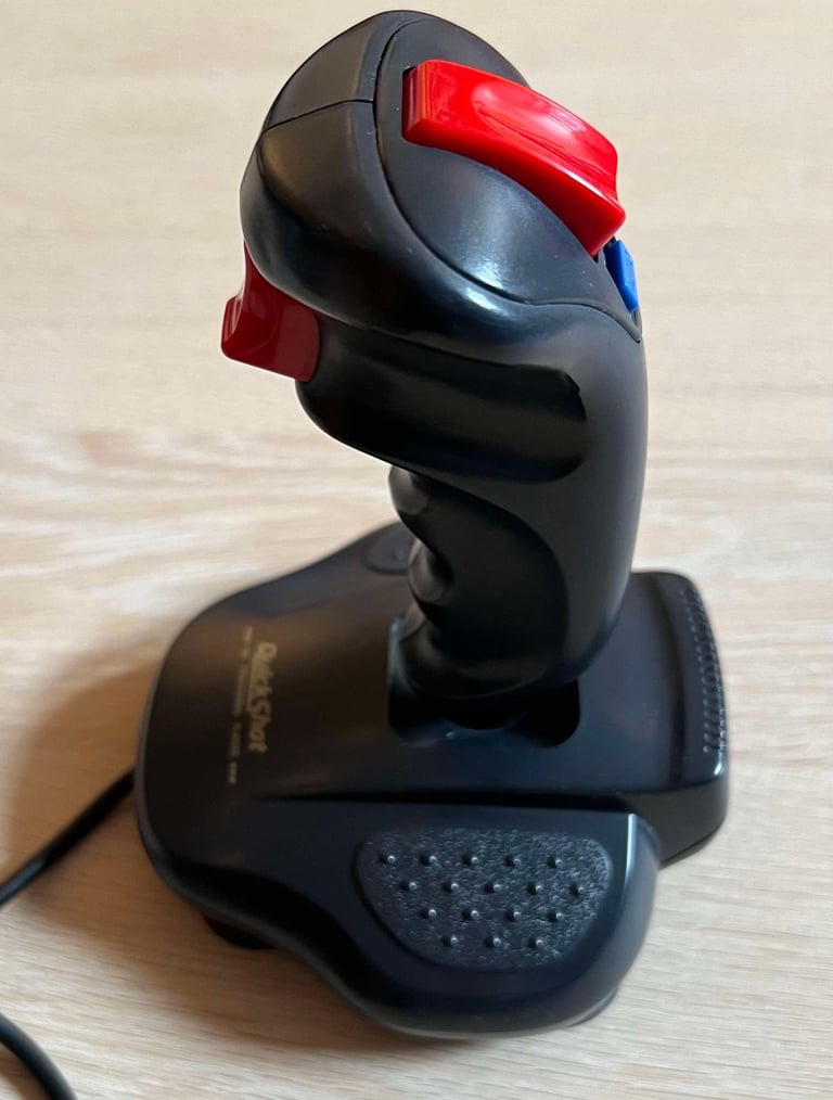
This Quickshot QS-137F appear to be in quite good condition from the looks of it. The Quickshot family, originally from Spectravideo, are known to use spring-loaded switches making the really nice "clicking sound". And this joystick does certainly give that good sound!
There are some slight slack in the directional motion when using the joystick, but I think that is normal. Both fire buttons, and the auto fire selector, feels and seems ok. When moving the joystick in the RIGHT/LEFT/UP/DOWN direction, the joystick makes that nice "click" sound, but it feels at bit slow. I guess that some lubrication of moving plastic parts and cleaning of the spring-loaded switches can help on the situation.
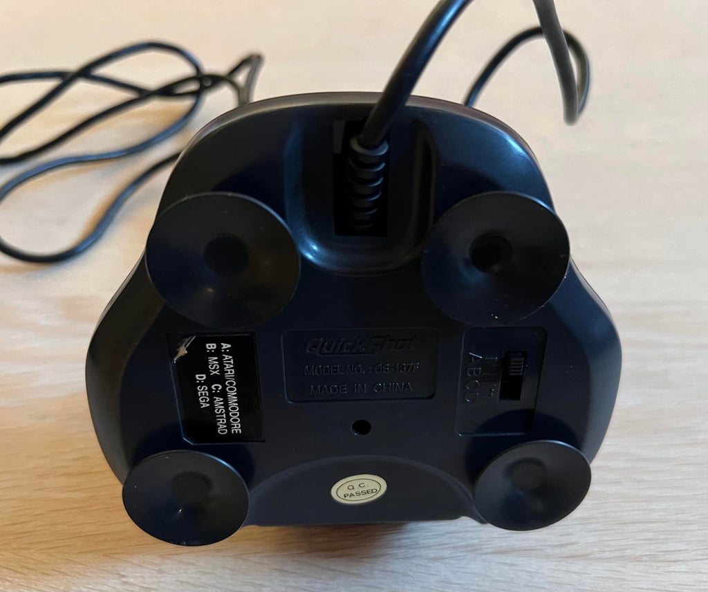
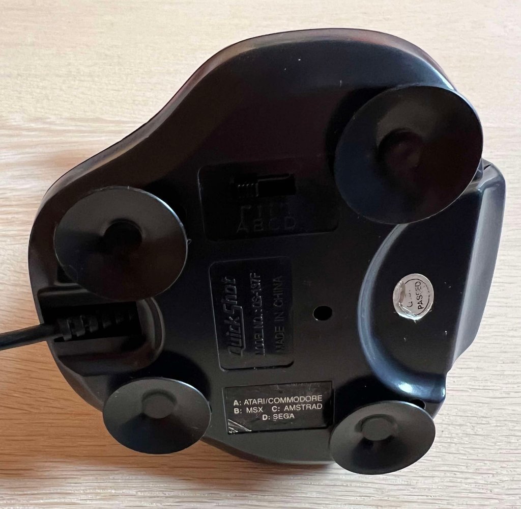
All four rubber feet are intact and with minimal tear and wears. Also, all the four screws holding the covers together are in place. Notice that this joystick can be used on several machines such as Atari/Commodore, MSX, Amstrad and Sega. A very cool function back in the late 80s / early 90s. The sticker showing which machine to support is a bit worn.
Quickshot joysticks with spring-loaded switches are known to require some repair/refurbish due to slight corrosion. We´ll see how it looks inside shortly.
Below are some pictures taken before refurbishment.






Refurbishment plan
To refurbish this joystick the plan is to do this trough the following steps:
- Clean, and remove stains from, chassis and all parts (and repair if required)
- Lubricate moving parts
- Clean and check the interior electronics (and repair if required)
- Verify joystick operation by testing
Disassembly
It is possible to disassemble the Quickshot SQ-137F, but it is not trivial. There are quite a few components inside and soldering is required. The first step of the disassembly is to remove the four screws at the bottom cover. These are partly covered by the rubber feet.
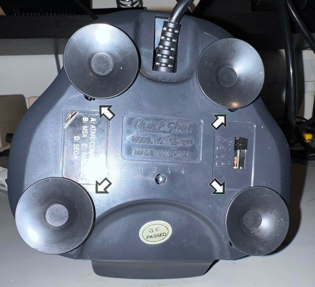

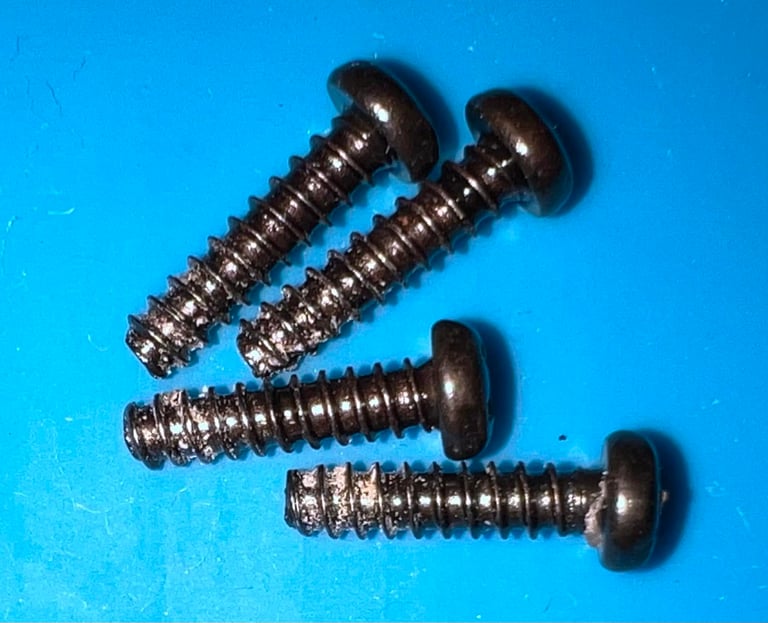
The four screws, which are in good condition, have the dimension 12 mm x 3 mm.

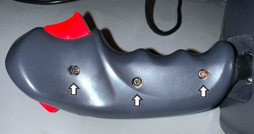
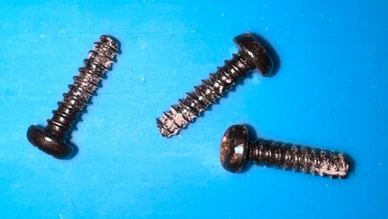
The joystick is laid on the side and the next three screws are removed. Note that these screws have the same dimension (12 mm x 3 mm) as the ones used in the bottom cover.


Carefully lifting away the right hand cover of the shaft exposes the interior. The interior consists of three main parts (see picture below):
The front fire button with a thin metal rod
The front fire button PCBA which can be detached
The top fire button module which consist of both the top fire button, the plastic bracket and the PCBA
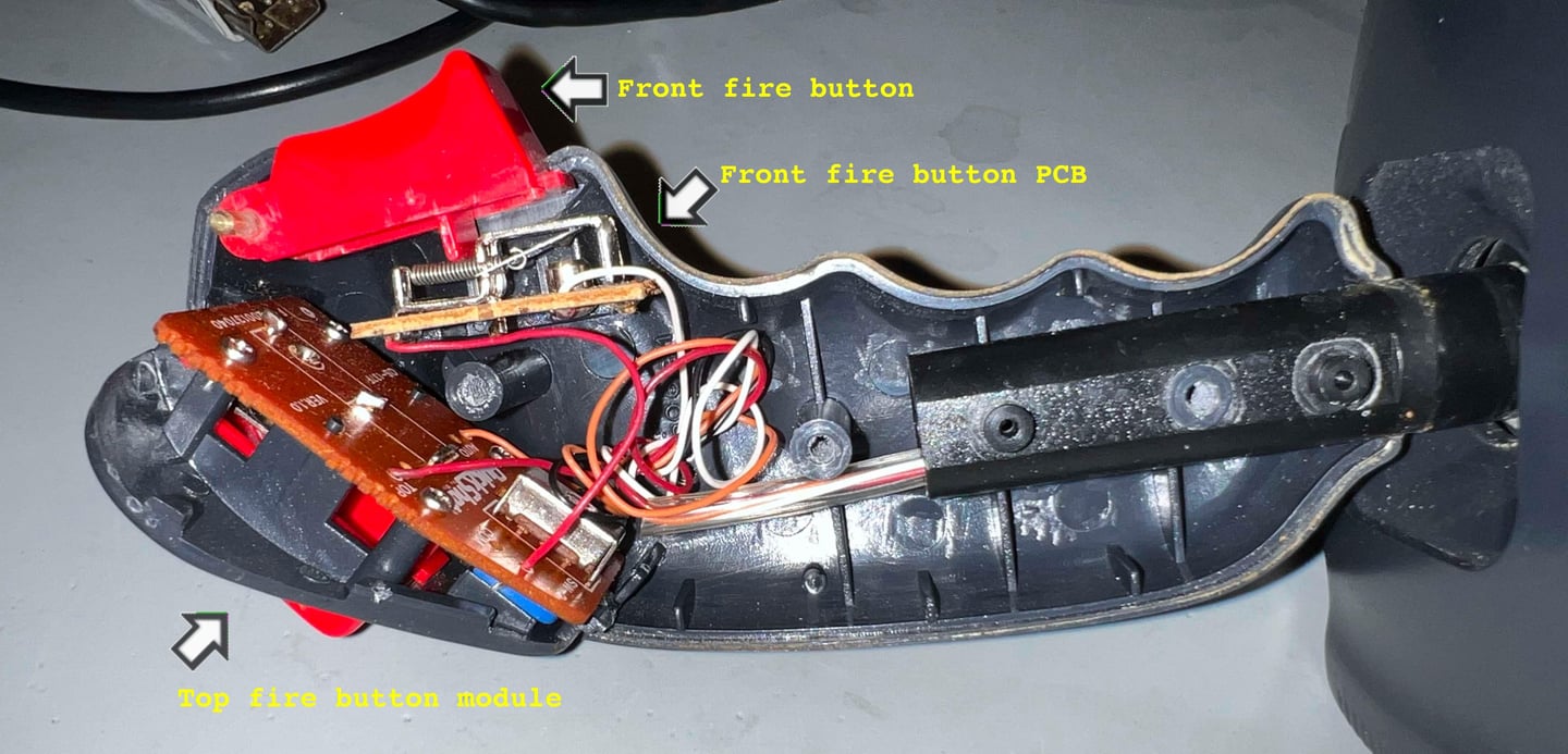

The interior of the shaft appear to be in good condition. I can not see any sign of damage. It is quite dirty inside, but other than that nothing much to worry about.
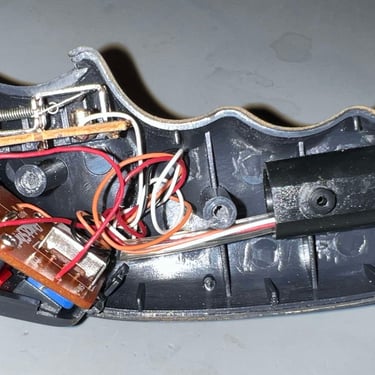
Each of the three parts are gently lifted away from the left hand side of the shaft cover. Below is a picture gallery of the process (click to enlarge).
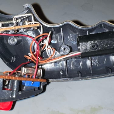
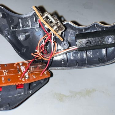
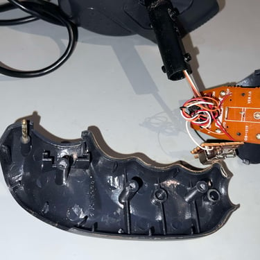
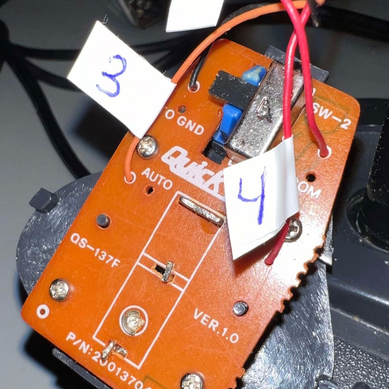
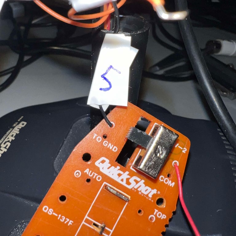
To continue the disassembly all the wires needs to be desoldered from the two PCBAs. It is good practice to use some tape to mark each of these to make sure nothing get messed up during re-assembly (ok, let´s me honest - it probably will be anyway). Not to document which-is-which cable, but below are some pictures from the process showing that each wire is carefully labelled (click to enlarge). Note that:
On the top fire button PCBA there are four small machine screws that must be removed (6 mm x 3 mm).
One of the wires (marked "1" i the picture gallery) is a cross-PCB wire between the two PCBs in the shaft
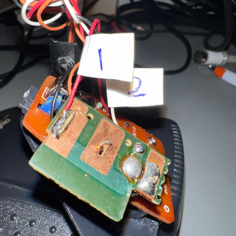
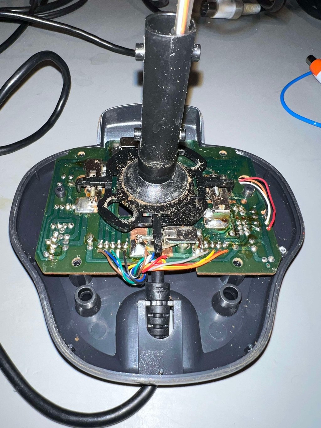
The wires are gently removed from the interior shaft and the top cover is lifted away. This exposes the interior of the base of the joystick. As can be seen from the pictures below the interior is very dirty. A lot of grease, dirt and I can clearly see signs of corrosion and oxidation. But this is to be expected. These Quickshot joysticks are known to be quite prone to interior corrosion - but we´ll fix that later.

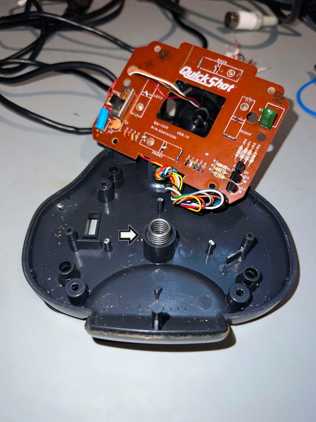

As can be seen from the picture above there is also a thick metal spring in the middle of the bottom cover. This is removed by pulling it straight out.
Finally, all the nine wires are desoldered from the base PCBA. This releases the joystick cable from the PCBA and the bottom cover is also free.
Exterior casing and plastic parts
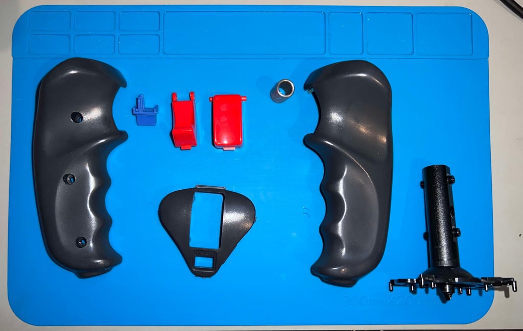
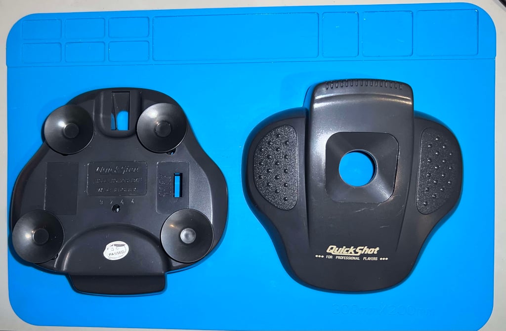
All the plastic parts are in very good condition. There are some dirt and grease, but other than that it looks very good I think (the outside looks way better than the inside). Below is a picture of all the parts before cleaning.
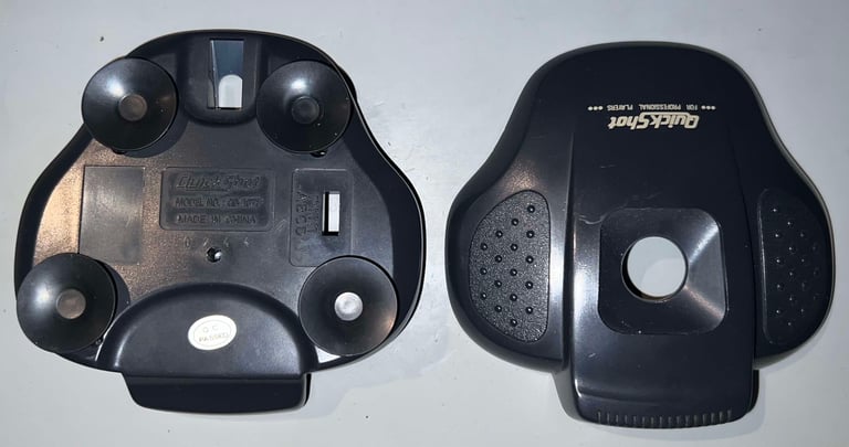

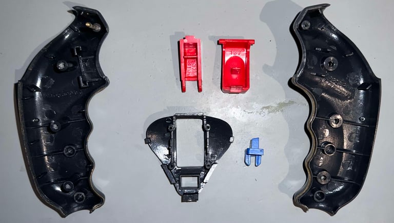

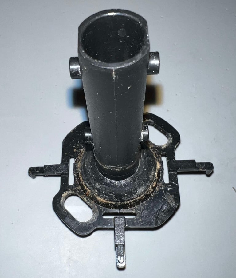

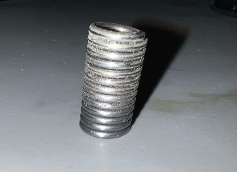

Everything is placed in a container filled with mild dishwasher soap for about 48 hours.
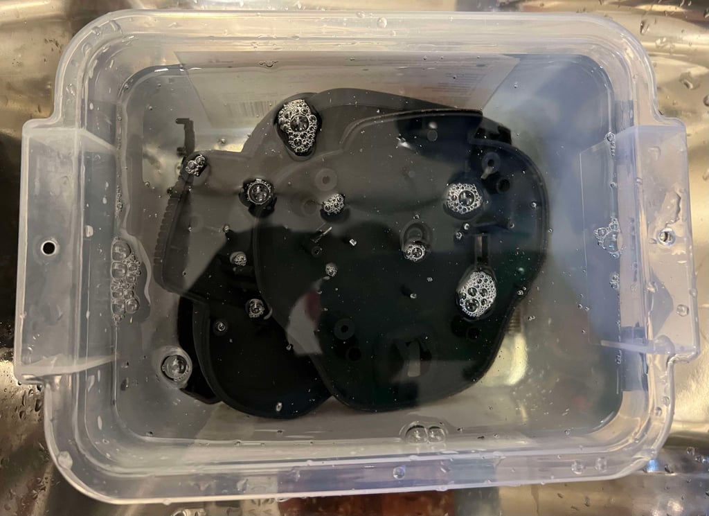

Not that the parts were very dirty before, but they look very nice after the bath. All the grease and dirt is gone.


PCBs and spring-loaded switches
The Quickshot QS-137F consists of three PCBAs:
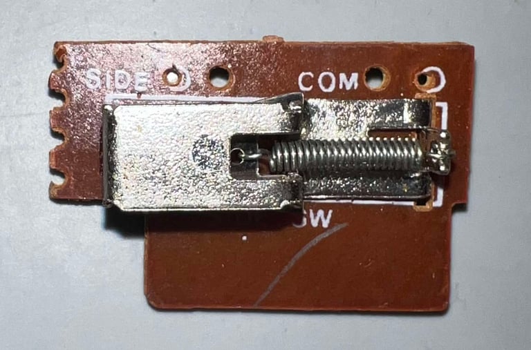
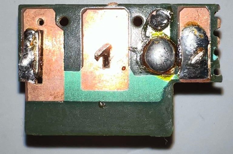
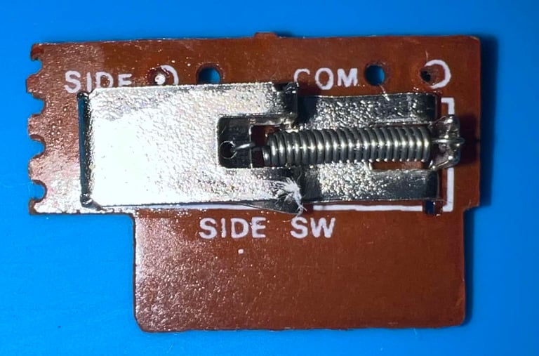
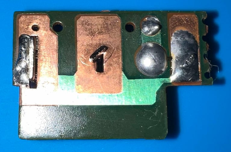
For the front fire button. This is the smallest of the PCBAs and consist of a single spring-loaded switch
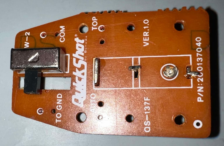
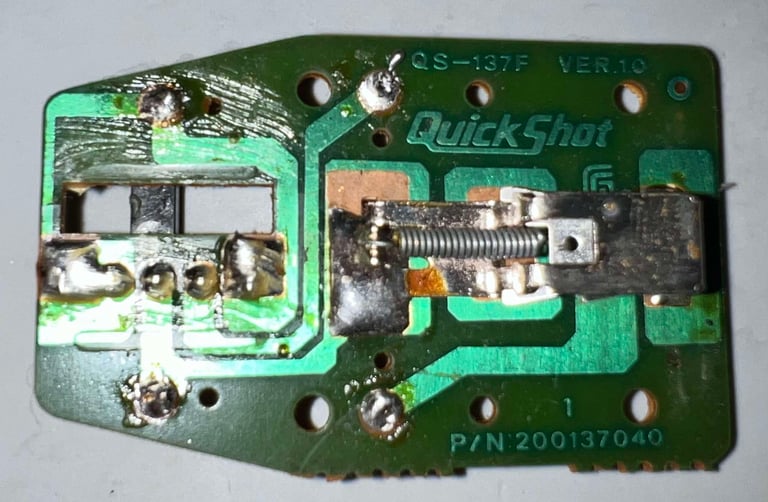
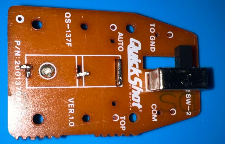
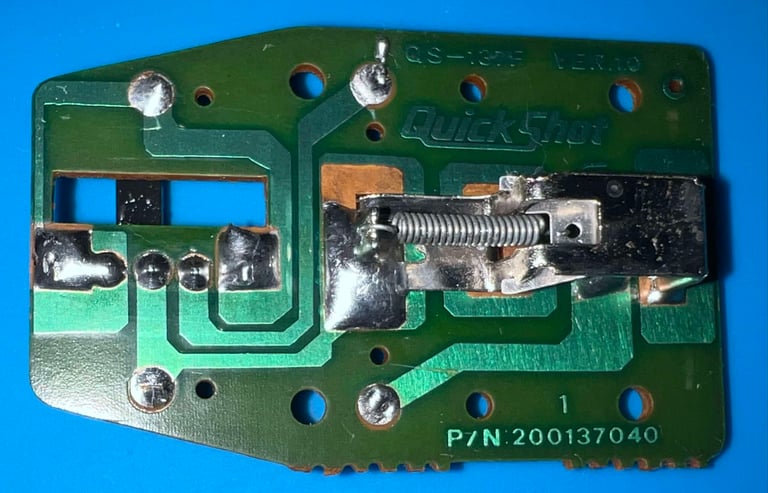
For the top fire button. This is the medium sized PCBA marked with P/N 200137040 for QS-137F VER 1.0 It consists of a single spring-loaded switch and a selector switch (to enable/disable the auto fire).
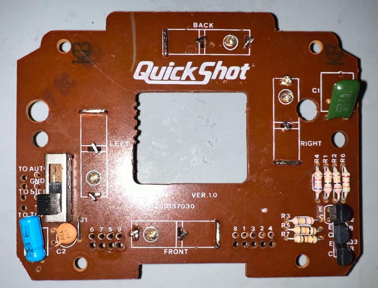
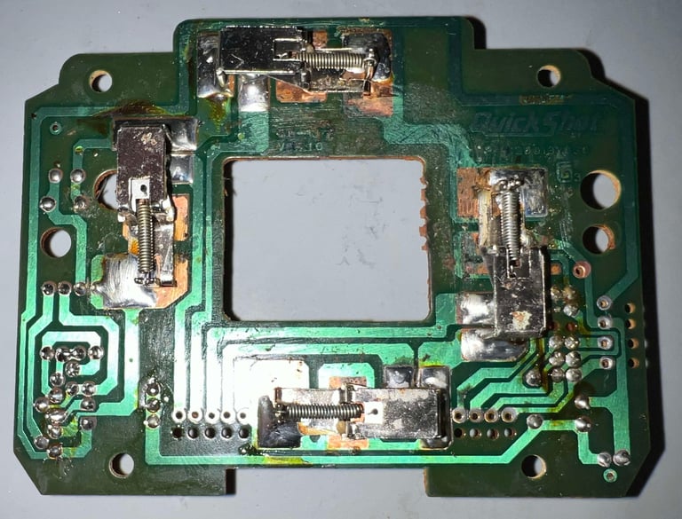
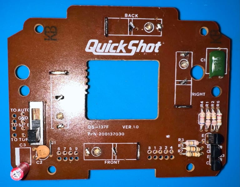
For the four directional motions (RIGHT/LEFT/UP/DOWN) and the auto fire circuit. Marked with P/N 200137030 for QS-137F VER 1.0. It consists of four spring-loaded switches, a four way selector switch (to choose the between compatibility modes) and a resistor/capacitor/transistor network (for auto fire and compatibility).
Visual inspection
Below are pictures of all the three PCBAs before refurbish. As can be seen all of the PCBs, and the components installed on them, appear to be in "ok" condition - but not in great condition. The main thing to notice, is that there is quite some flux residue, dirt and corrosion. It is not straightforward to see the corrosion from these pictures, but with closer inspection there are corrosion of the large PCBA on some of the traces and the small metal plug/stem inside the spring-loaded switched. However, this is to be expected.






Refurbishing the base PCBA
The board for the base (controlling the direction, compatibility modes and auto fire) are refurbished in three areas:
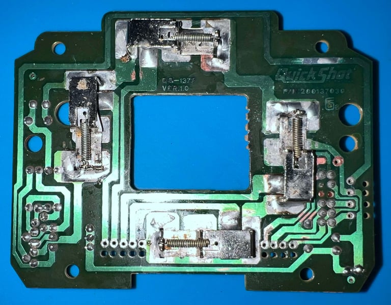
Restoring the copper traces and pads. These are heavily corroded and oxidized. All corrosion (hopefully) is scraped off with a sharp metal tool, the area is neutralised with some diluted white vinegar, cleaned with isopropanol, re-soldered with fresh solder and then covered with some transparent nail polish. It does not look perfect afterwards, but way better than before. Also, the stems/pins which is normally covered beneath the spring-loaded switches are brushed with a copper (and steel) brush. This scrapes away all the corrosion. As with the traces these are also processed with vinegar, isopropanol and fresh solder (but of course not with nail polish).
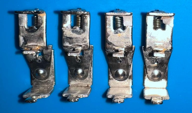
Restoring the spring-loaded switches. These do in fact look quite ok, but they are covered in some kind of... eh... sticky stuff? I think this is just fat, grease and dust which has accumulated during the years. The four switches are placed in a jar filled with isopropanol for about 48 hours.
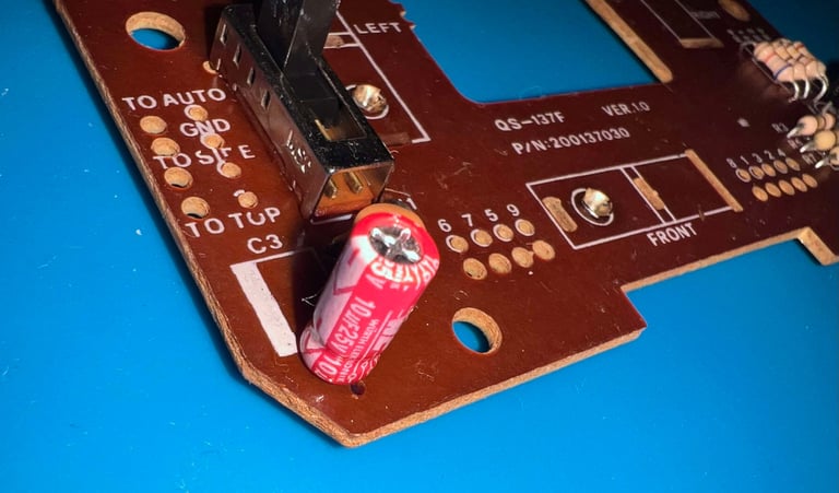
Replacing the electrolytic capacitor. There is an old 10 uF [25 V] capacitor on the PCBA. This one is desoldered and a new one is installed.
Below are some pictures from the process and the end result.




Refurbishing the fire button PCBAs
In contrast to the base PCBA the top- and front fire button PCBA is not so dirty and corroded. There are some grease and dust, but this is most superficial. Both the PCBAs are cleaned properly with mild soap water, dried and cleaned with isopropanol. Below are some pictures after the cleaning.




... And then some required repair
When doing refurbishment I often do some testing along the way. And it turns out that there is some repair required to make the joystick work properly. There are two main identified issues:
The UP/RIGHT direction is sometimes registered as being pushed (when it is not). And the signal appear to oscillate
The AUTOFIRE does not work always
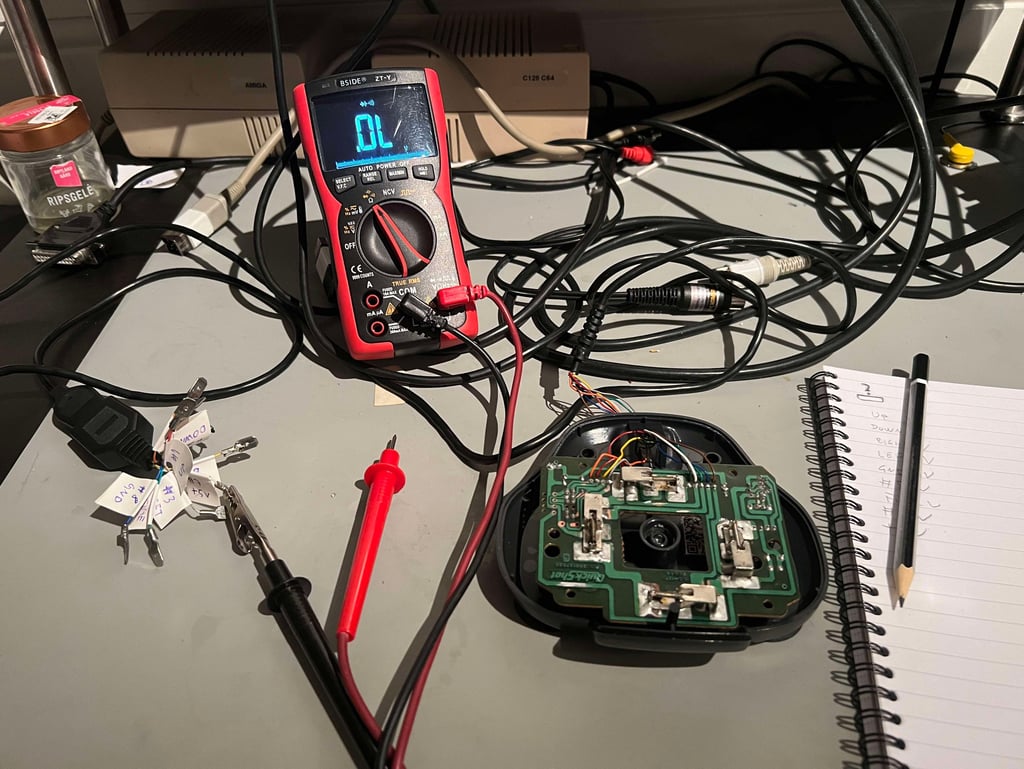

My initial though is that there is something wrong with the resistor/capacitor/transistor circuit. I can not see anything immediately wrong with these, but I choose to desolder them anyway. The PCB was so heavily filled with "goo" (everything from flux residue to corrosion) that I think it is good to check these components closely. The components desoldered are listed in the table below. Please note that I do not know what all of these values should be, but is what I measured them to be.
This turns out to be a red herring. I can not find any faults with the components. But I do find two other potential candidates for faults:
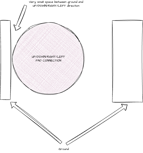
On some of the spring-loaded switches there is a < 1 MOhm resistance between ground and the UP/DOWN/RIGHT/LEFT connection
There is no ground connection on the C2 and C3 capacitors. They are floating.
I did not manage to take any good pictures, but in the sketch below I try to explain what caused the <1 MOhm resistance between the UP/DOWN/RIGHT/LEFT direction pad in the spring-loaded switches. The area between the ground connection and the direction pad is very small (<1 mm). I am not 100 % sure, but that I think that a tiny amount of soldering has come over which causes intermittent connection.

To fix this I decide to cut a bit of the ground area to make more space. This may not look very nice, but it will work without any problem, and should prevent the intermittent fault.
The second issue is fixed by adding some solder beneath the LEFT spring-loaded switch (I had forgot). See picture below.
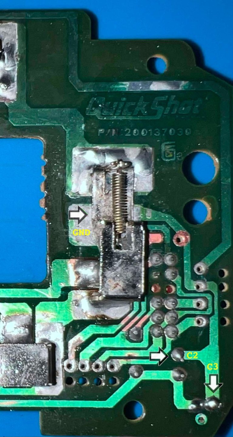

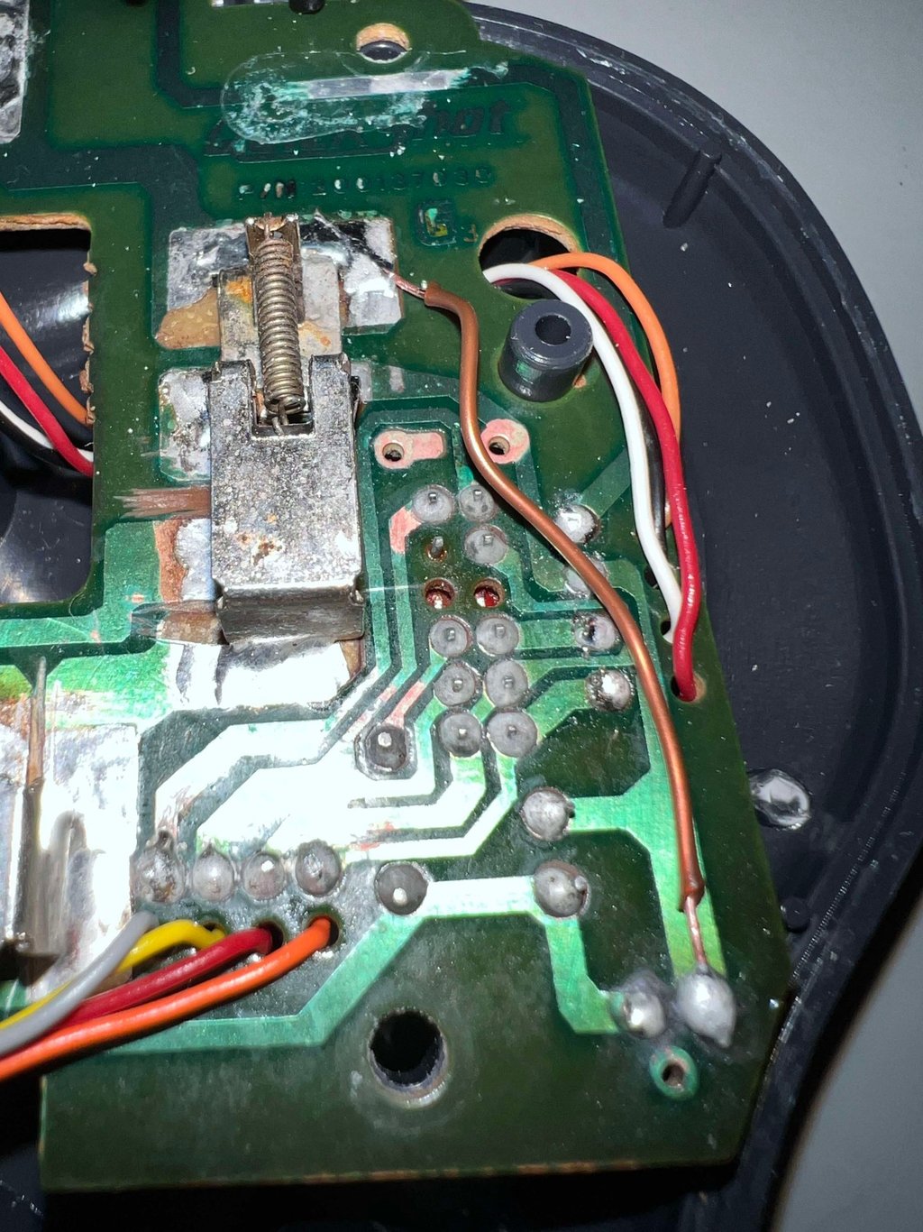
Below is a picture after repair. Note that a small bodge wire is also applied between ground and C2/C3 - to make sure the ground connection is proper. Also you can see some of the areas beneath the spring-loaded switch which are cut.

Testing
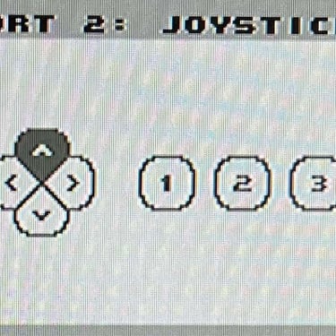
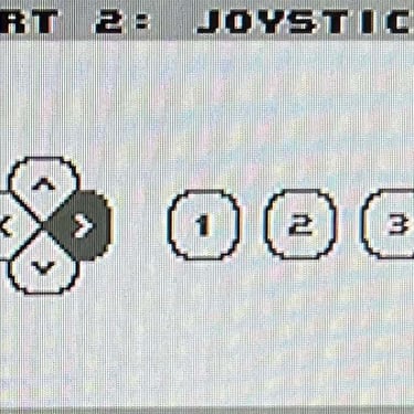
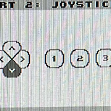
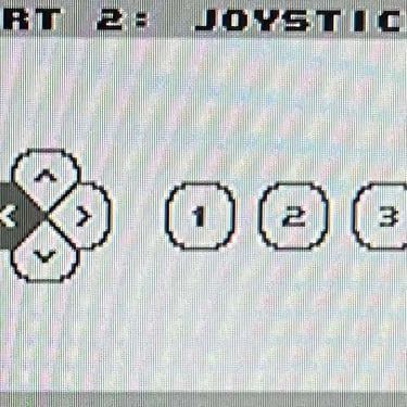
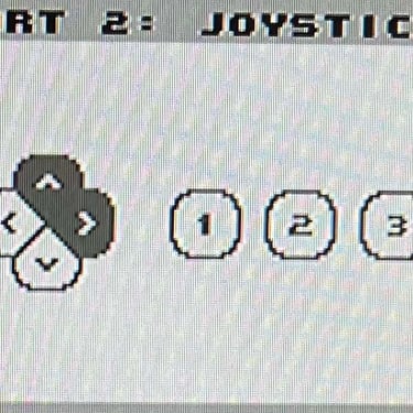
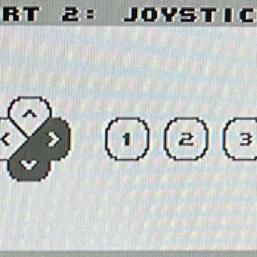
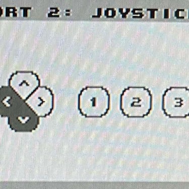
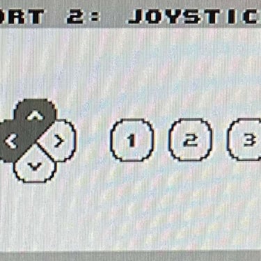
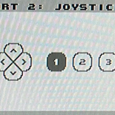
To verify that the joystick work as it should I check it with the Joyride software. Result is that all directions and fire buttons works fine works as expected. All tests pass.
Final result
"A picture worth a thousand words"
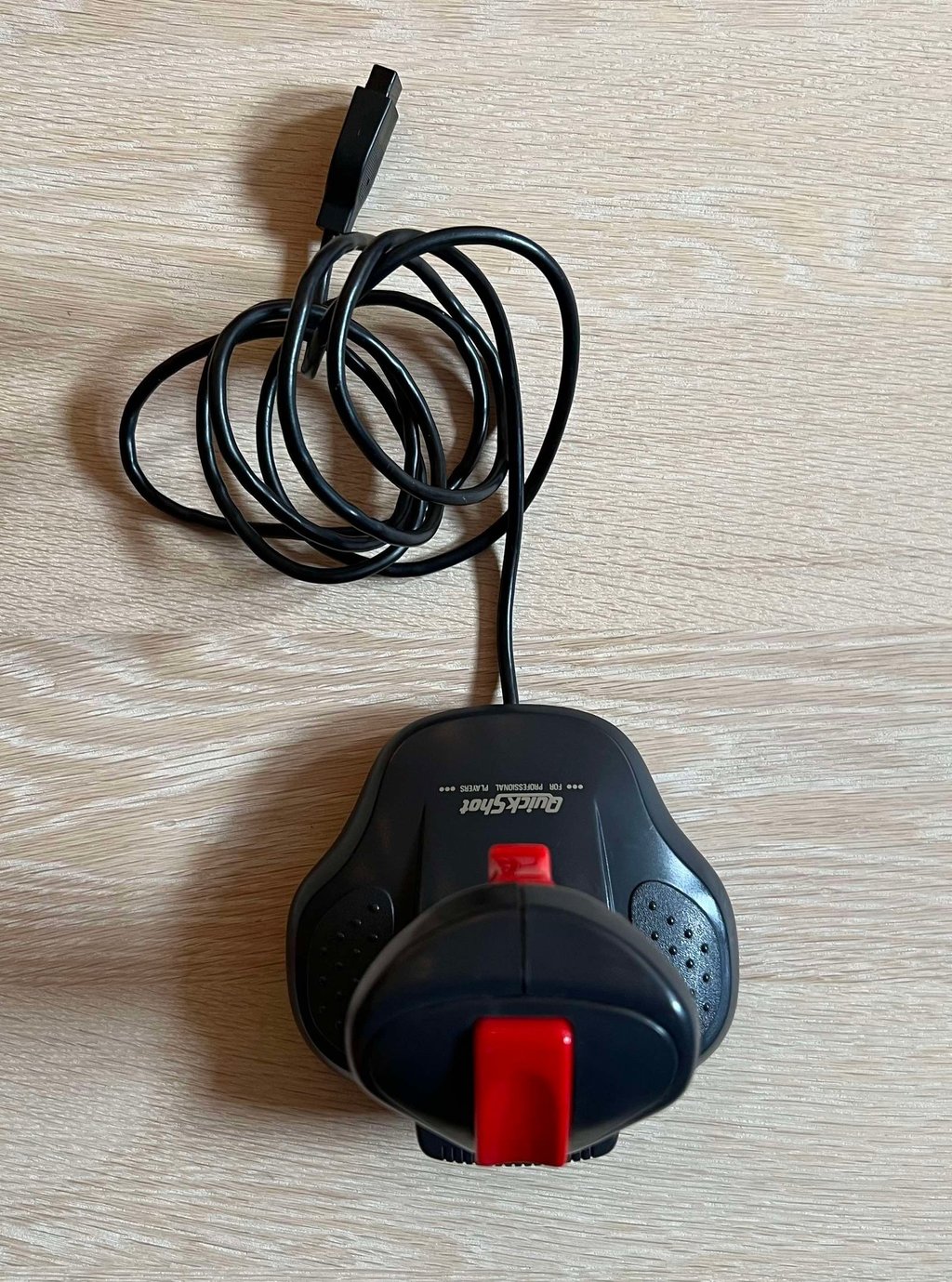
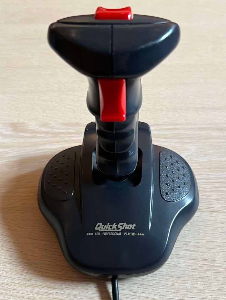
Below is a collection of the final result from the refurbishment of this Quickshot QS-137F joystick. Hope you like it! Click to enlarge!






Banner picture credits: msx.org
