
QuickShot II
Turbo
QS-111
Starting point
"I feel the need... the need for speed!" - Maverick (Top Gun, 1986).
Back in the 80s the graphics used in flight simulators were perhaps not the best (compared to modern games), but we had the coolest flight-stick-looking joysticks! The QuickShot II Turbo QS-111 is in my opinion an icon from that era (in the series from Spectravideo). Jump into the cockpit of your F-16 and buckle up!
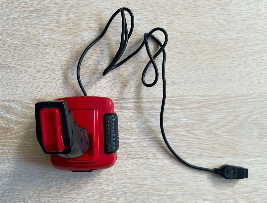
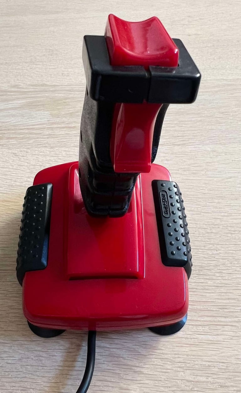
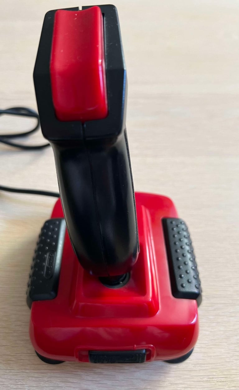
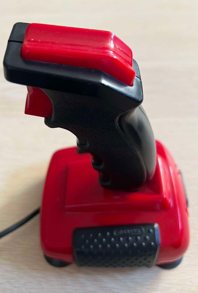
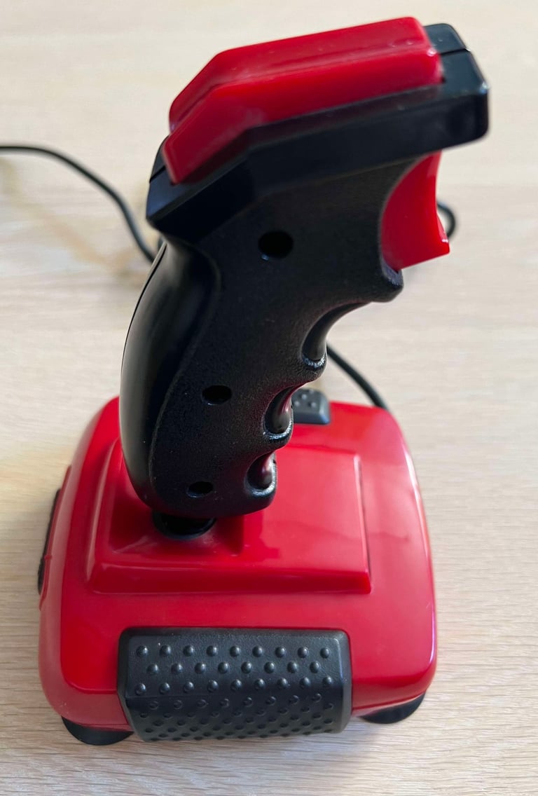
From the outside the joystick does look ok - eh... well no... IT IS NOT! The joystick shaft is tilted to the left like the leaning tower of Pisa, and in addition it is completely stuck. It is not possible to move it in any direction. Hope that it is not broken beyond repair.
The autofire selector only slides from side to side. There are no "grip" to anything. Either the plastic parts are broken off, or the PCB inside is completely misaligned. The autofire button is marked "AUTO FIRE / MANUAL FIRE / CPC 464". I guess the latter is referring to Amstrad compatibility.
I´ll give this a 50/50 chance for the possibility of a repair...
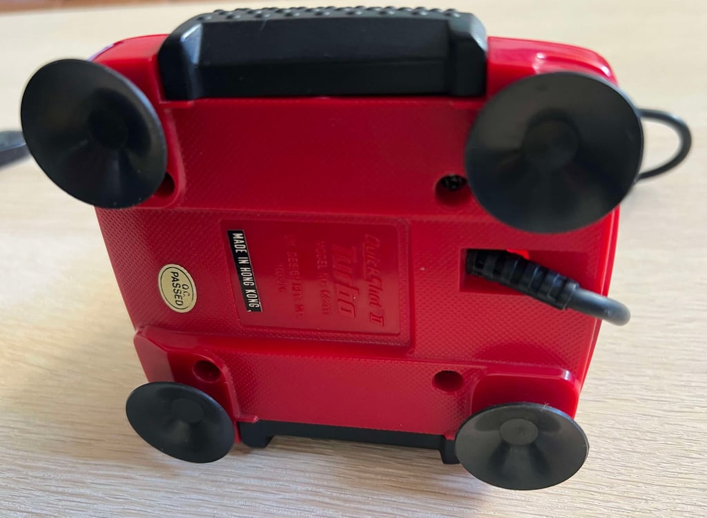
Below are some pictures of the joystick before refurbishment.






Refurbishment plan
To refurbish this joystick the plan is to do this trough the following steps:
- Clean, and remove stains from, chassis and all parts (and repair if required)
- Clean and check the interior electronics (and repair if required)
- Verify joystick operation by testing
Disassembly
First step of the disassembly is to remove the three screws (3 mm x 14 mm) from the joystick shaft.
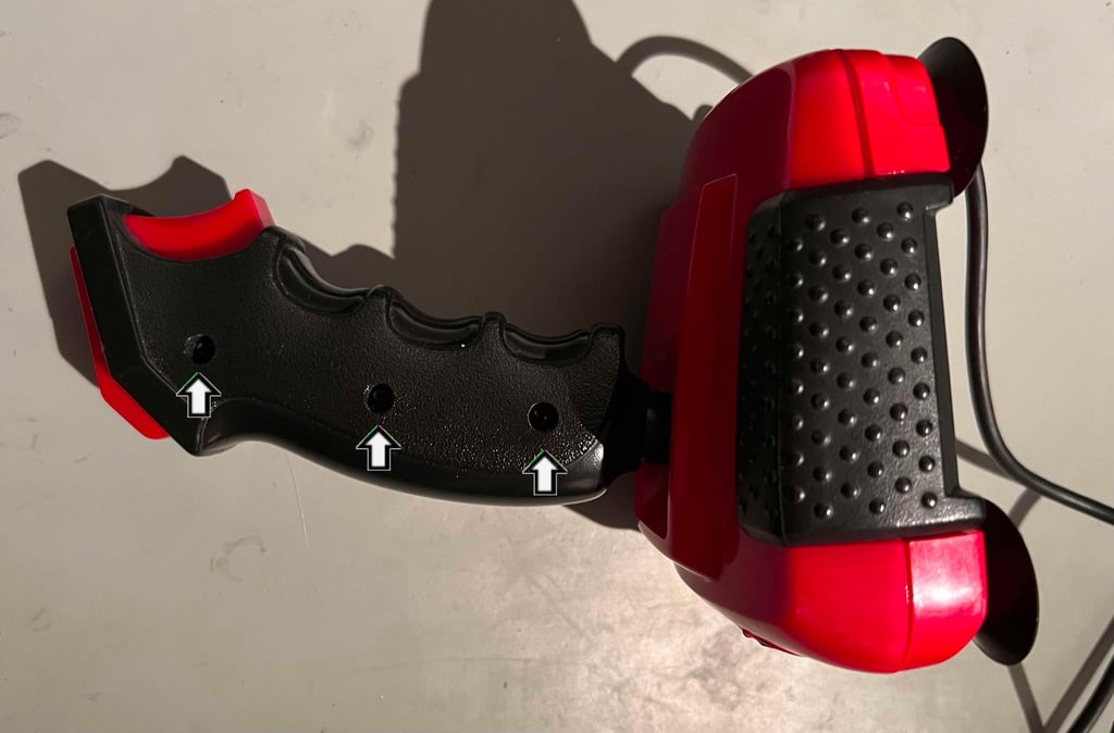

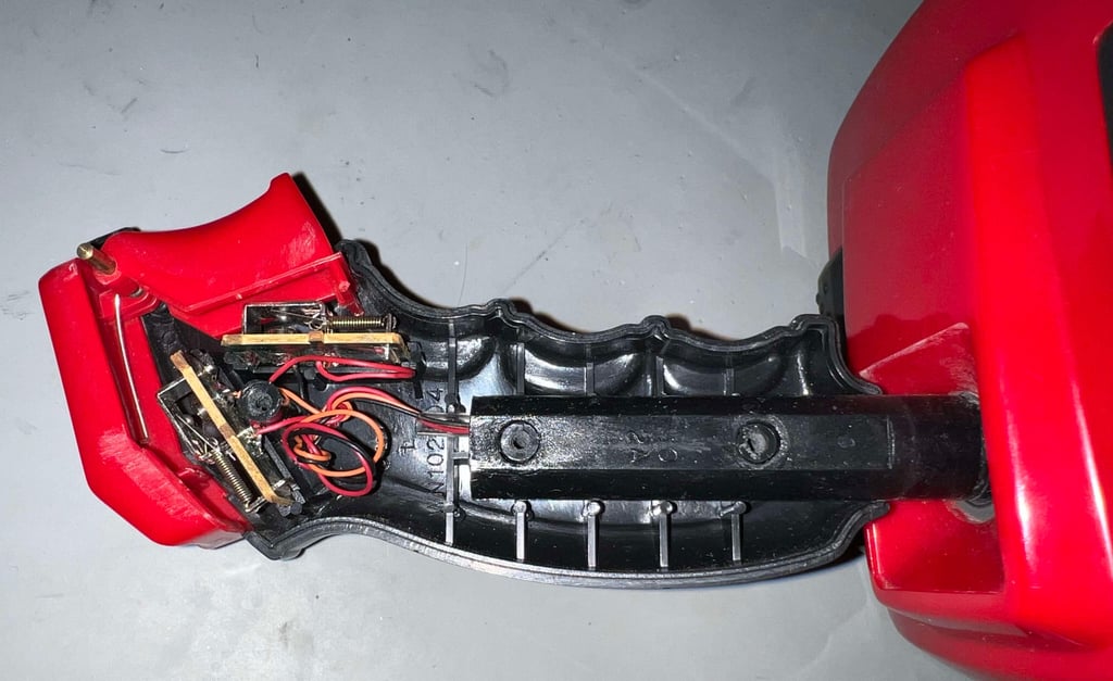
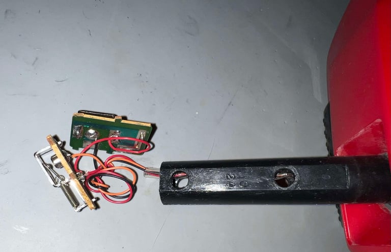
When the screws are removed the right hand side of the shaft is removed. This exposes the inside of the shaft. Now the two fire buttons can be removed (they are held together by a small spring), the two small PCBs can be removed and the right hand side of the shaft can be pulled out of the inner shaft. See pictures below.

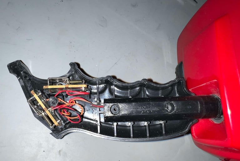


The four screws at the bottom have the same dimension as those in the shaft: 3 mm x 14 mm. After the shaft is removed the bottom cover is disassembled.
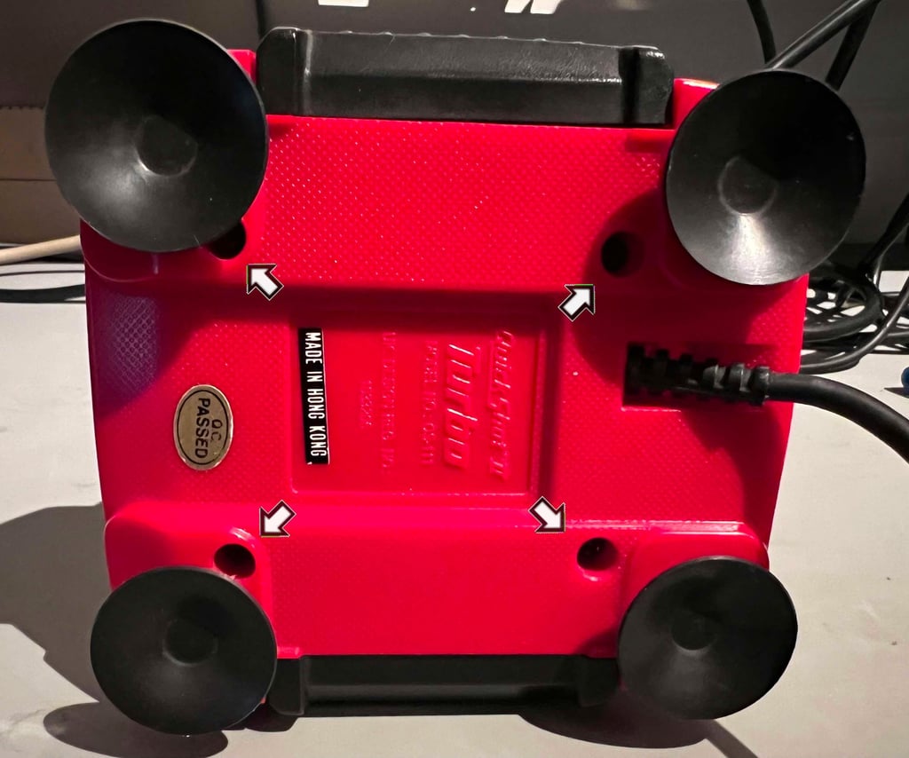

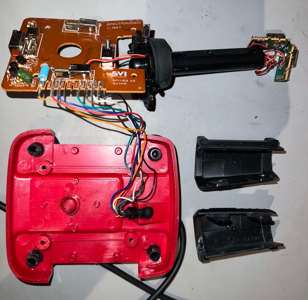
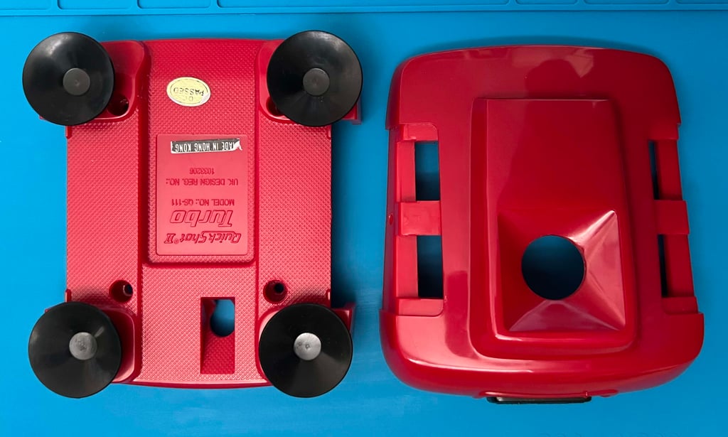
With the four screws out of the way the bottom cover is removed and the interior is revealed. I notice that there are some dust and grease (which is to be expected), but I also notice that the PCB seems a bit... bent?
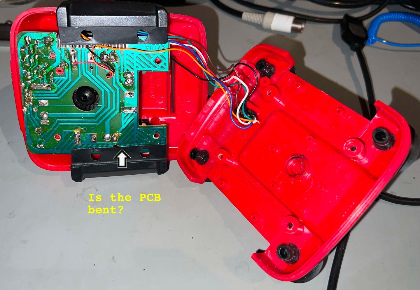

The parts are pulled away from the bottom cover, and now it is obvious that the PCB is broken. In the picture below you can see where the bend is - between the right hand side of the upper switch and the text "SPECTRAVIDEO 1987". Luckily, it does not seem that the PCB is completely broken in two pieces so hopefully it can be (partially) repaired.

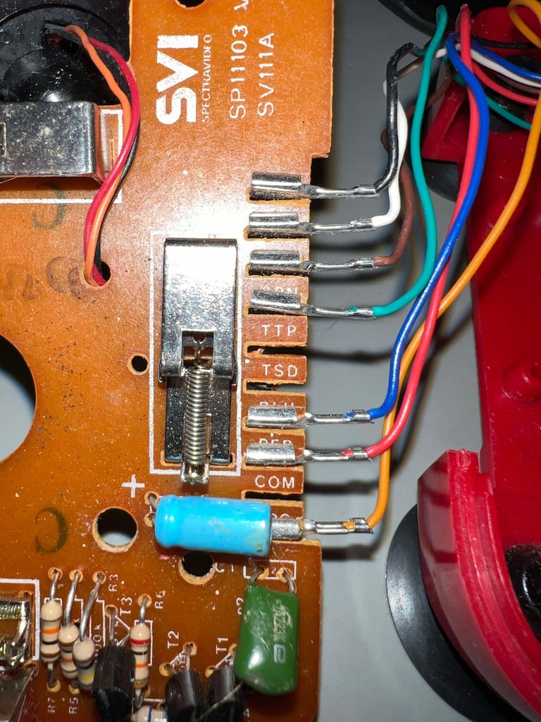
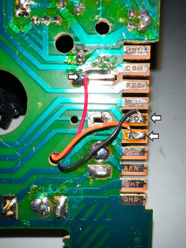
All of the seven cable shoes from the joystick cable are removed (picture left side / top picture) and then the three wires from the fire buttons are desoldered from the PCB (picture right side / bottom picture).


Exterior casing and plastic parts
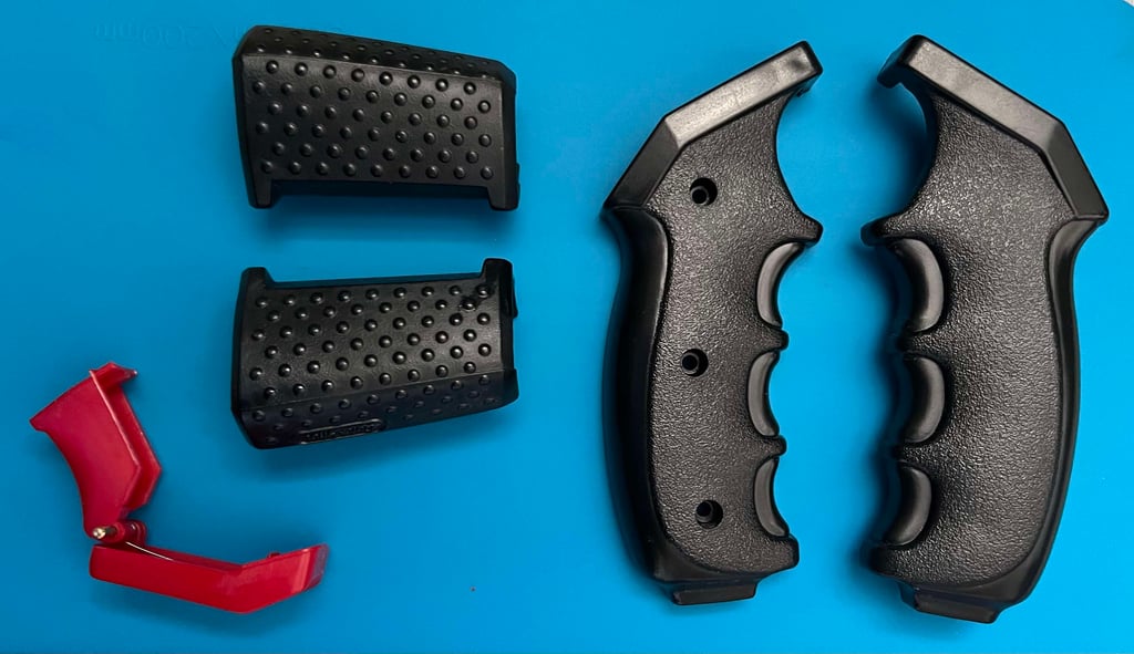
First things first - all the plastic parts are placed in a box filled with mild soap water for about 24 hours. After the long bath the parts are dried and cleaned with some glass cleaning spray. Looks as new (?)


Attempting to repair the autofire plastic bracket
It turns out that the small black plastic bracket used to toggle between "AUTO FIRE/MANUAL FIRE/CPC 464" is partly broken. One of the two small stand-offs has broken (and is missing). These two stand-offs are used to grip the interior switch (soldered to the PCB). But even if I had the missing stand-off I do not think it would suffice to only glue it back on. It would probably break quite fast. Instead I try a different approach - with some hot blue I make a large blob of glue and cut this to resemble the broken stand-off. The distance between the two stand-off needs to be 3 mm to hold the small notch on the switch inside.
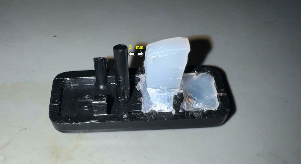

WARNING: I do not know if this fix will last very long. I think it is the best I can do with my skills - and I know that it will be better than just gluing a thin stand-off. The best would probably be to design and 3D print a complete new part, but this is not within my knowledge to do unfortunately.
Electronics and spring-loaded switches
The PCB is marked SVI-Spectravideo "SP11103 V2 SV111A". With closer inspection there are some issues with the PCB:
The PCB is bent (but not broken) in the area between two spring-loaded switch for the UP and LEFT direction
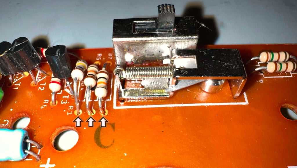
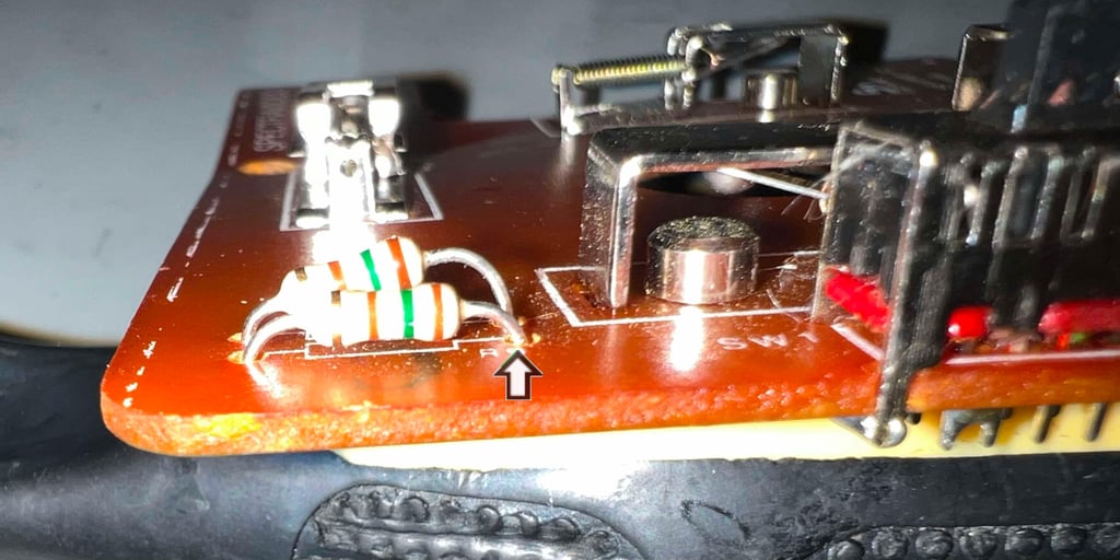
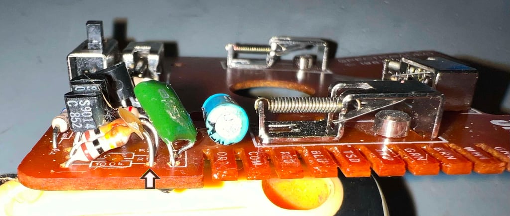
Several of the resistors are not flush with the PCB. It appears that these resistors are "thrown" onto the board and soldered
There is a significant amount of flux residue on the PCB
Some of the spring-loaded switches (those in the fire button area) appear to be a bit more oxidized than the others
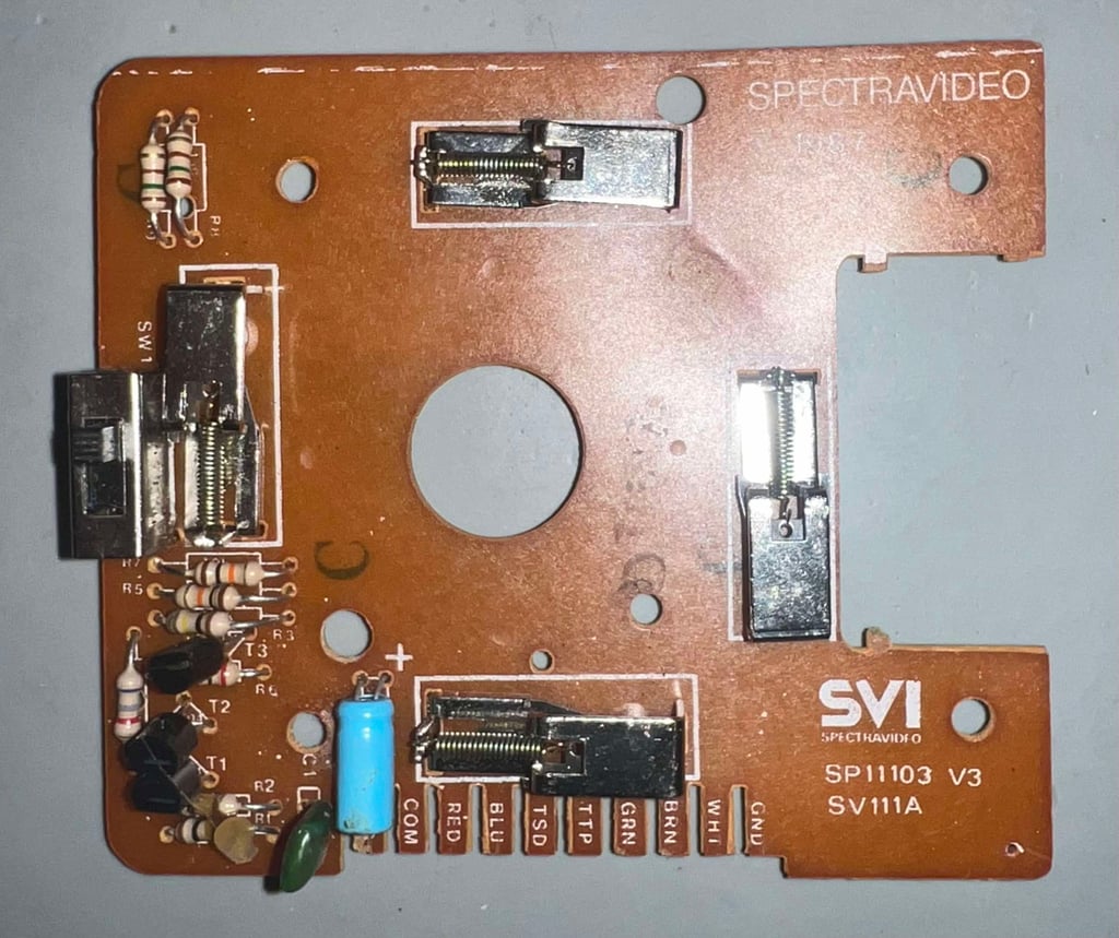

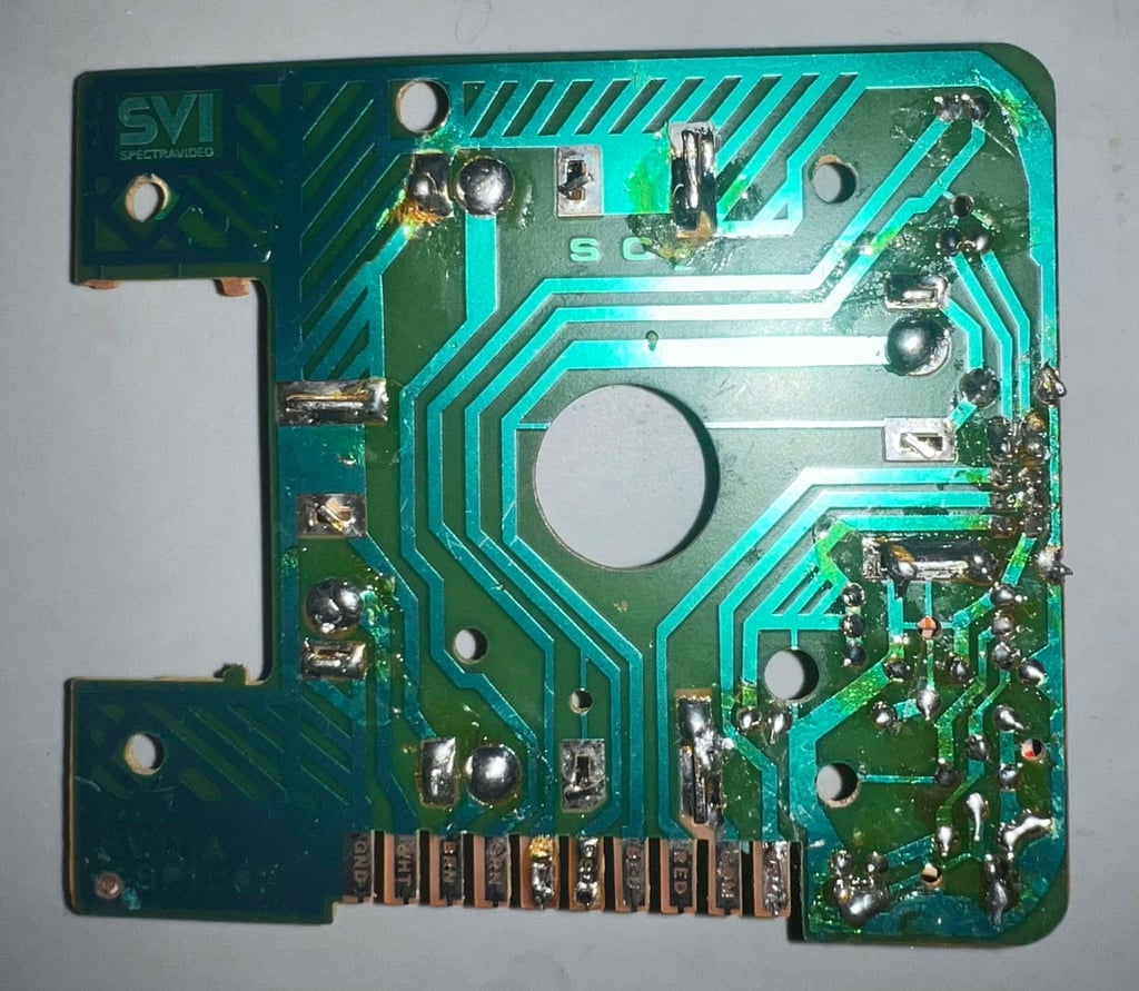

Below are some pictures of the resistors which are not soldered flush with the PCB. Why?! I do not see any reason why not bothering taking the time to press them down so that they are flush?



A measure to fix the bent PCB
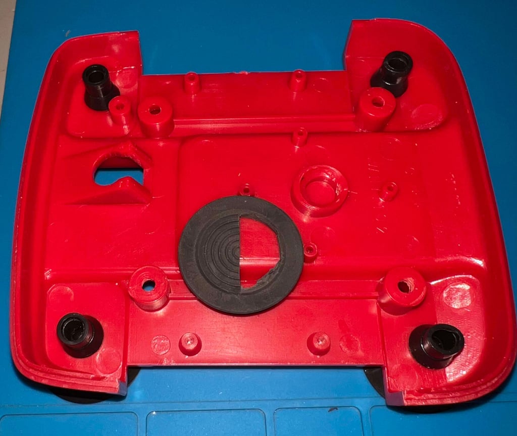
The PCB is bent, but it is not broken in half. An attempt to push the PCB back to original shape a customised rubber ring is placed just beneath the PCB. See picture below.

When the pictures goes haywire
Ok, either I forgot to take pictures from the refurbish OR they got lost(?). Anyway, I will try to explain what I have done with the PCB and the spring-loaded switches:
All flux residue is removed with plenty of isopropanol and a tooth brush
The resistors which were not flush with the PCB are now flush. All those resistors were re-soldered and pressed flush to the board.
The two spring-loaded switches on the fire buttons are gently rubbed with some fine sand paper and cleaned with contact spray
One of the wires on the fire button were loose. This wire was soldered back.
A word about the auto fire
The auto fire feature on this joystick works a bit different that most other joystick. When the switch is set ot "AUTO FIRE" the auto fire function is enabled immediately - and not when the fire button(s) is pressed. At first I though that this might be a fault, but when checking another similar QuickShot QS-111 joystick the result is the same.
Testing
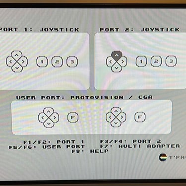
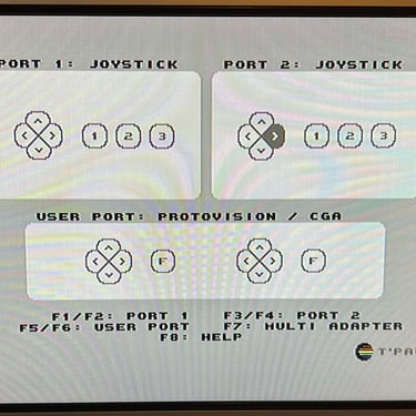
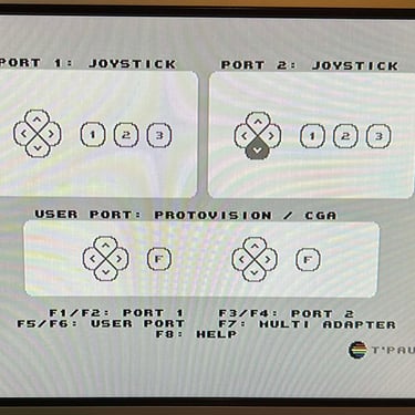
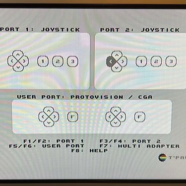
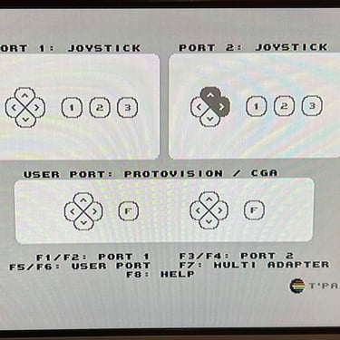
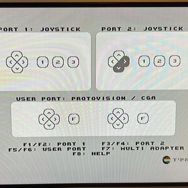
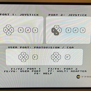
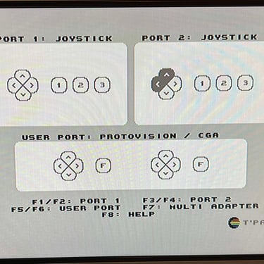
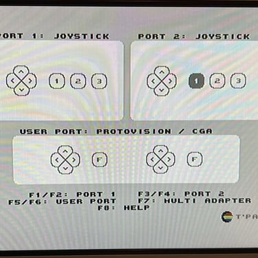
To verify that the joystick work as it should I check it with the Joyride software. Result is that all directions and fire buttons works fine works as expected. All tests pass.
Final result
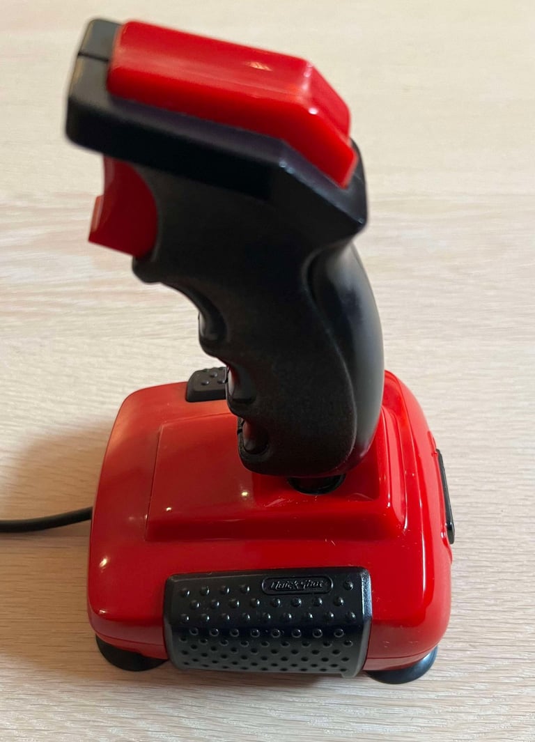
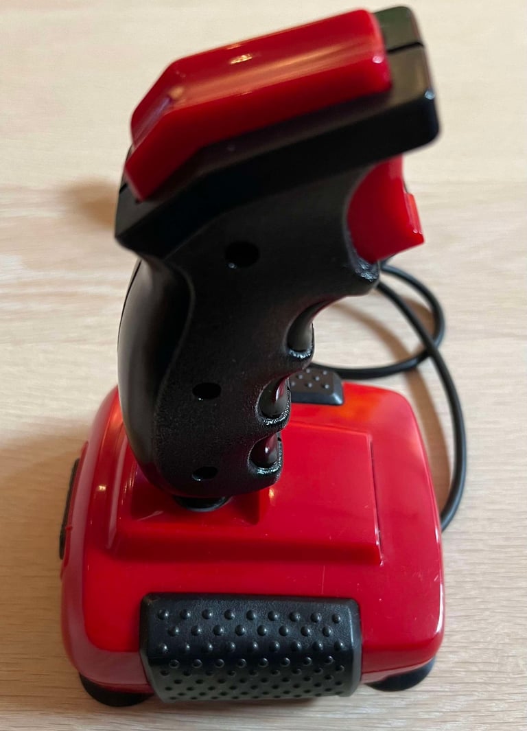
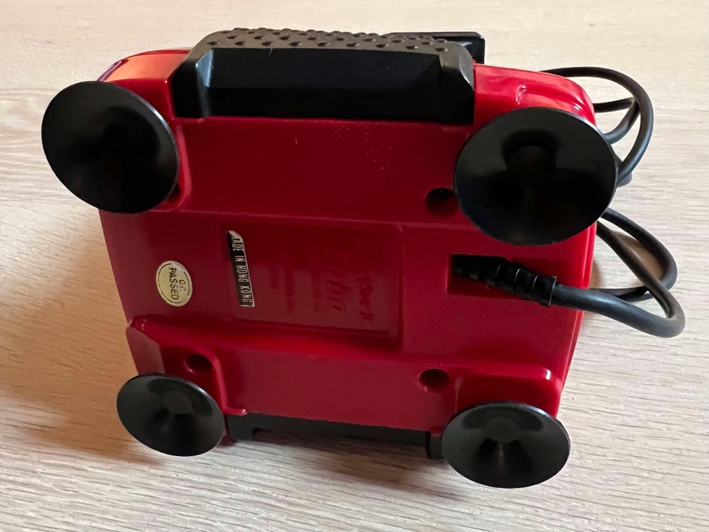
A picture worth a thousand words"
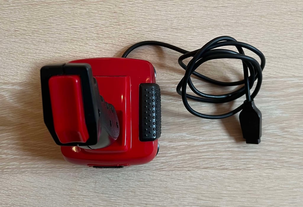
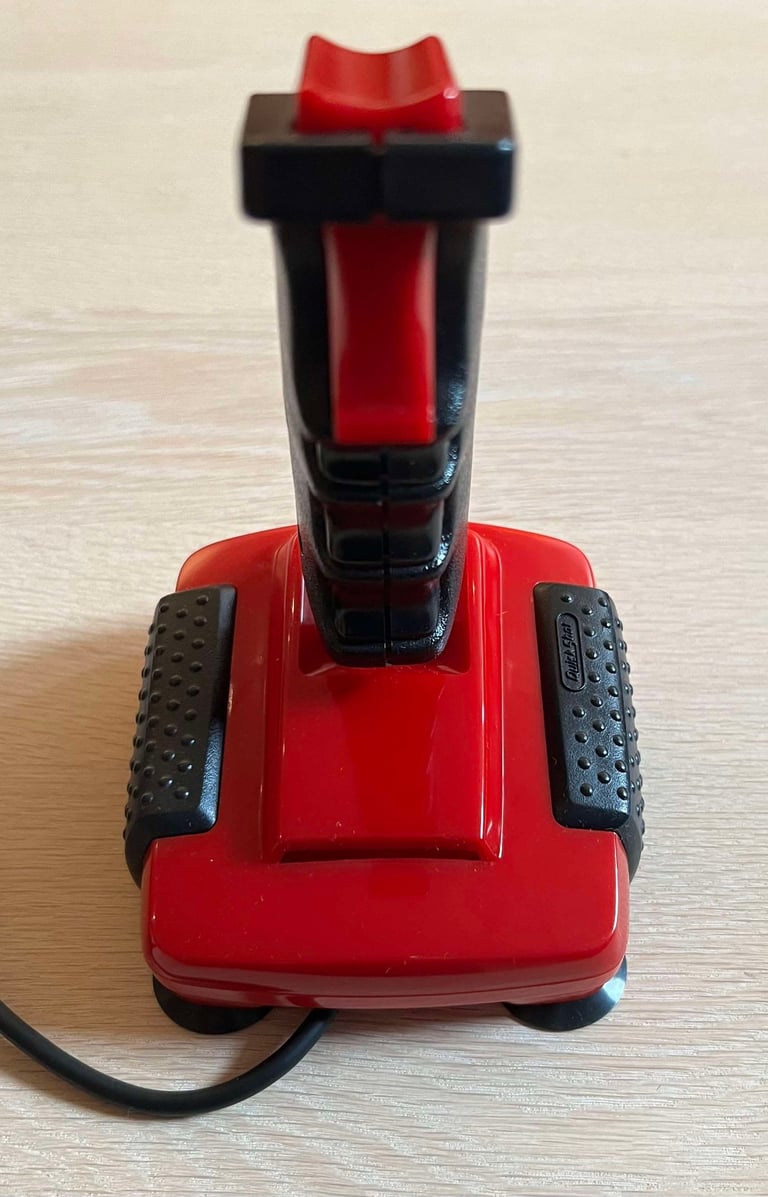
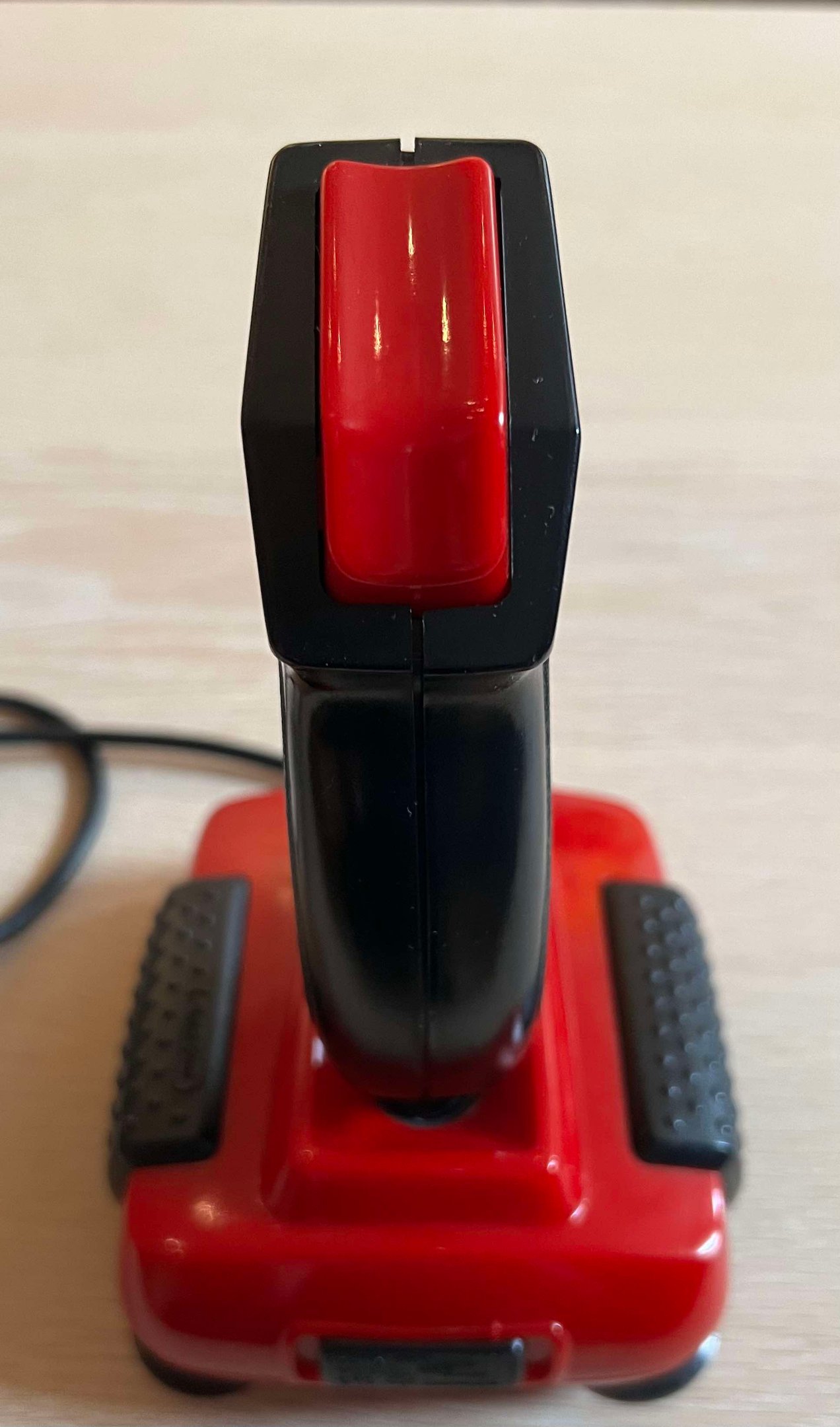
Below is a collection of the final result from the refurbishment of this QuickShot II Turbo joystick. Hope you like it! Click to enlarge!






Banner picture credits: msx.org
