

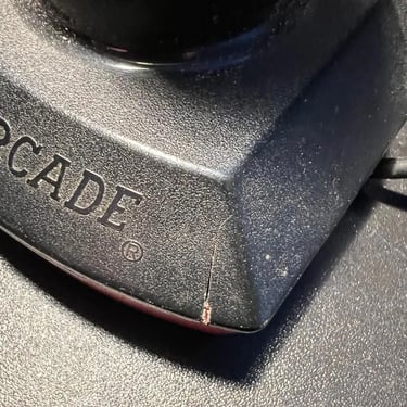
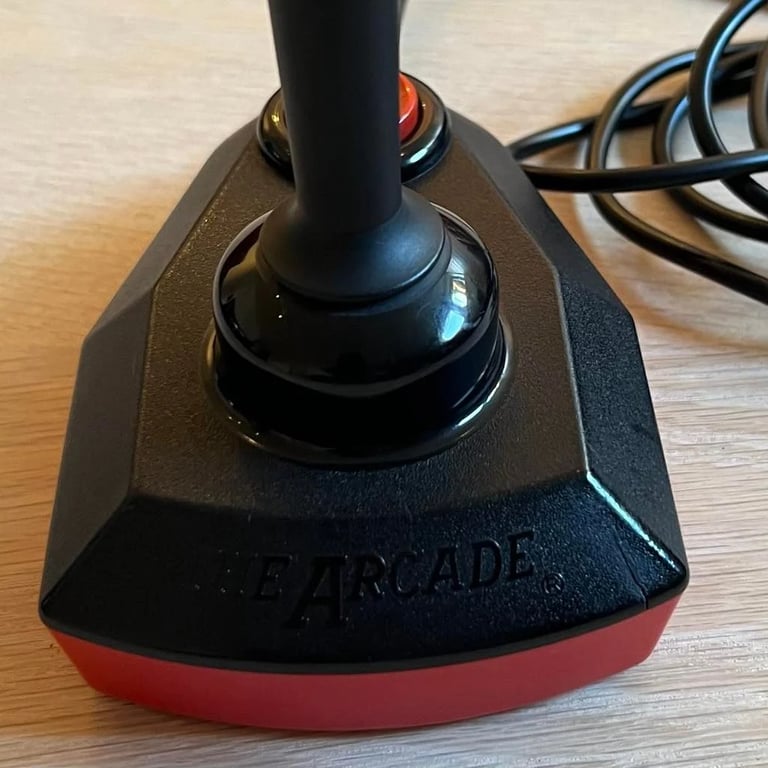
The Arcade Turbo
Refurbishment plan
To refurbish this joystick the plan is to do this trough the following steps:
- Clean, and remove stains from, chassis and all parts
- Clean the PCB
- Replace the joystick cable
- Verify joystick operation by testing
Chassis
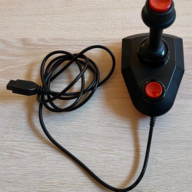
This joystick looks bad - really bad. I don´t think the pictures actually shows how bad it looks. It´s dirty, sticky, smells of nicotine and the cable looks like it´s been tortured... The rubber feets are really nasty... yikes!
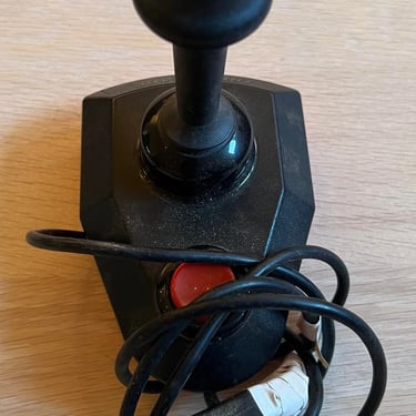
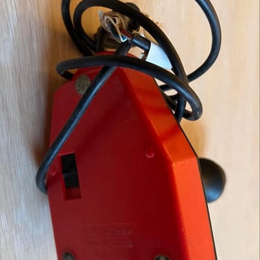
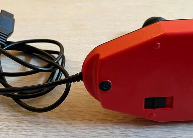
I notice that there is a switch on the bottom of the chassis. Not quite sure what the purpose of this switch is, but we´ll figure it out later. Also, there is a small crack in the right side corner of the top cover - nothing serious I think, but needs to be checked.
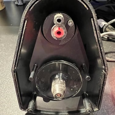
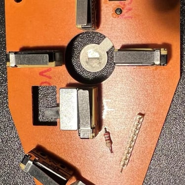
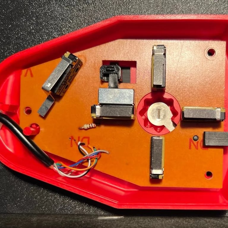
The joystick is disassembled by removing the three rubber feets and the screws beneath. The interior doesn´t look bad at all! There are some dust and grease on the PCB and the switches. The cable is a mess: it is twisted and it looks to me to be a replacement cable. The reason for that is that all the wires from the 9-pin flat connector on the PCB are cut about 3 cm from the connector. And here there are 9 new(?) wires soldered on and each wire have insulating tape wrapped around it. This is definitely not from factory... and this must be fixed.
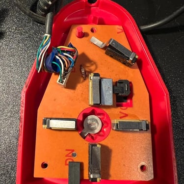
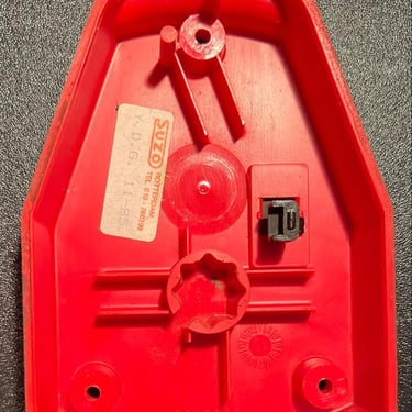
Notice the little sticker. This is an original sticker from Suzo saying "Y.D.G. 11-85". Could this mean November 1985? Anyway, I kind of like to keep this sticker so I gently remove it using heat from a hair dryer and a sharp knife.
The little crack in the right side corner is glued carefully (from the backside). I can't see that this crack will impact the functionality in any way, but I think it's wise to glue it anyway.
Cleaning the chassis is done by placing the parts in luke warm water with some mild dishwasher soap for a couple of hours. This removes most of the dirt and grease. The last part of the cleaning is done by using glass spray and some isopropanol.
PCB cleaning
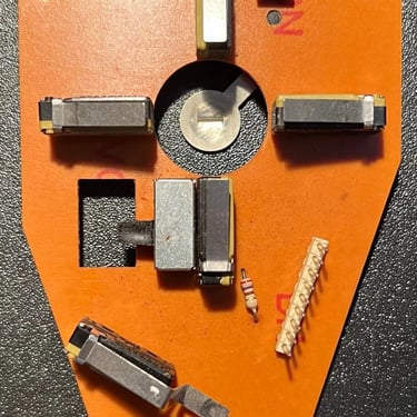
The PCB looks fine - it's a bit dirty but that's to be expected. I clean the PCB with luke warm water and some dishwasher soap. But, when cleaning PCB with tap water it's very important to use compressed air to get all the water out of the microswitches and use isopropanol (lots of!) to vaporise the water away from the PCB. If you don't do this you can experience corrosion later.
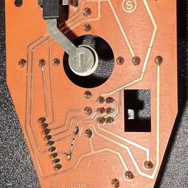
Below you will find four pictures. The two first shows the PCB before the cleaning, and the two last shows the PCB after the cleaning. Again. the PCB looked quite ok from the start, but a good clean is crucial for a good end result.
Joystick cable
The joystick cable is in a VERY poor condition. I don't think it even works, and I don't plan to spend time on testing it. It needs to be replaced.
In the original design the joystick cable was connected to the PCB via a straight 9-pin connector. This makes sense in regards of functioning as a strain relief and also a quick way of assembling/replacing the cable back in the 80's. But today I don't quite see it the same way: I think it's way better to actually solder the 7 wires directly to the PCB and to add an additional strain relief. This would prevent any loose contact due to an old connector when using the joystick. So even if this is some more work I choose to desolder the existing 9 pin connector and solder a new joystick cable to the PCB.
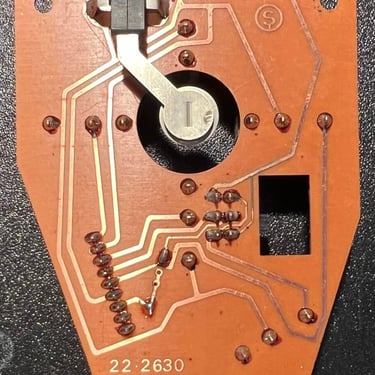
To desolder the 9-pin connector everything works fine. I'm not using the desoldering station, but only solder wick and the hot air gun. The connector is easy to remove - no traces liftet.
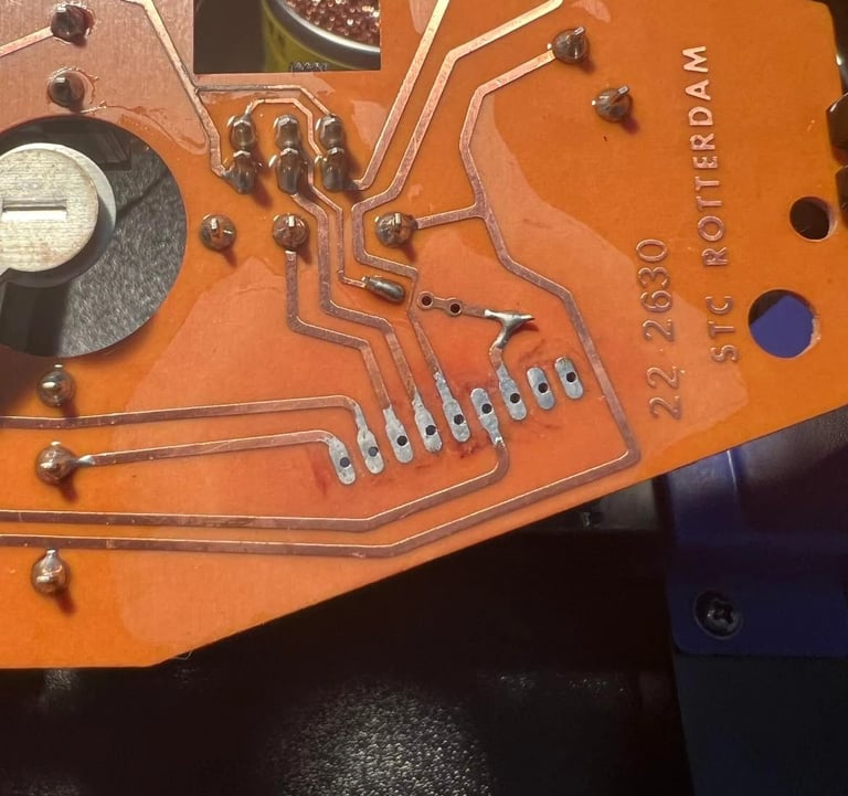

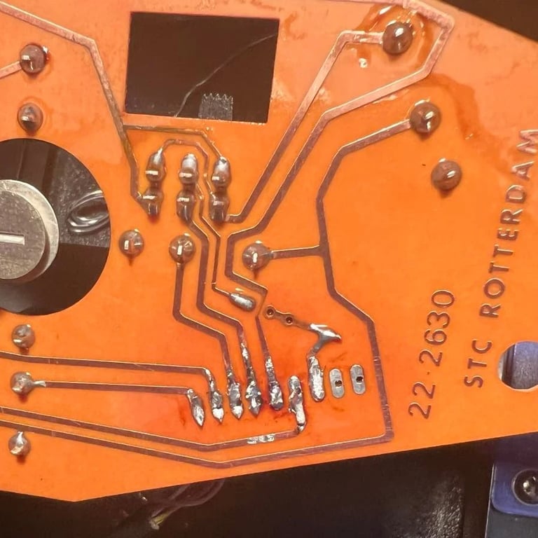
I then solder on the 7 wires from a brand new cable required for the joystick to operate as original (please note that this joystick also use the +5V pin which is not always used). Now, here's what I learned: these new cables are very flexible (which is nice!) but quite thin. So to solder these on the PCB was not so easy as expected. Therefore the soldering does not look as good as I hoped, but it should be more than enough from a "connection" point of view. In addition I managed to lift a trace since I managed to switch the UP/FIRE cable while soldering - and had to desolder/solder again. Note: this is does not impact the operation of the joystick in any way, but when doing refurbishment I want to be transparent also on my faults.
The end soldering result doesn't look perfect, but it works very well as far as I can see. And also; please note that I've added a strain relief using a cable tie. So now you should be ready to play so games using the joystick as much as you would like:-)!
A quick note about why I don't think the soldering result "look" nice: the new 9-wire cable use wires which are much thinner, and flexible, than the original cable. I think this is good - they would probably last longer before they break. But, on the downside they are a bit harder to solder on the PCB I think...
Testing
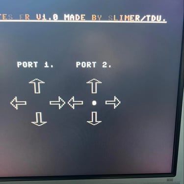
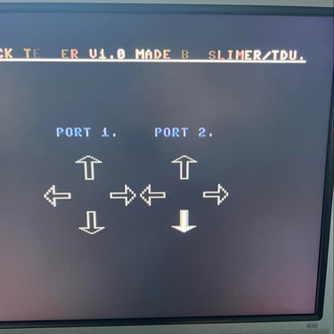
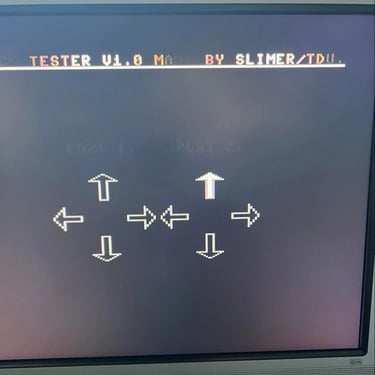
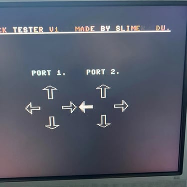
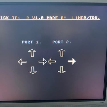
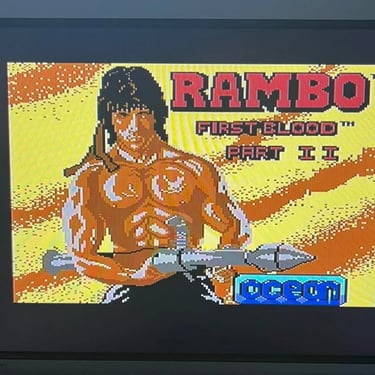
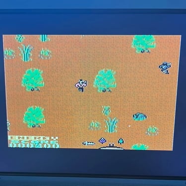
Ok, I need to admit it: I just love this part. Not to just verify that the joystick works with the the joystick test software - but to PLAY some C64 games! Absolutely love it! I always show the "boring" pictures from the C64 joystick tester, but I also play games such as Rambo, Commando and Wizard of Wor just to make sure that the joystick is functional.
I never quite understand the meaning of switching between the top and bottom fire switch? By using the main switch in the bottom of the joystick you can choose between the top- and bottom fire. Why not just use both? Nevertheless, this was the original design so we'll just leave it like that - it works.
Final result
Here's some pictures from the final result. I'm quite happy with it! Looks nice - and it's good to know that this is a high quality joystick!
Banner picture credits: SdeVries