
The Arcade Turbo
Starting point
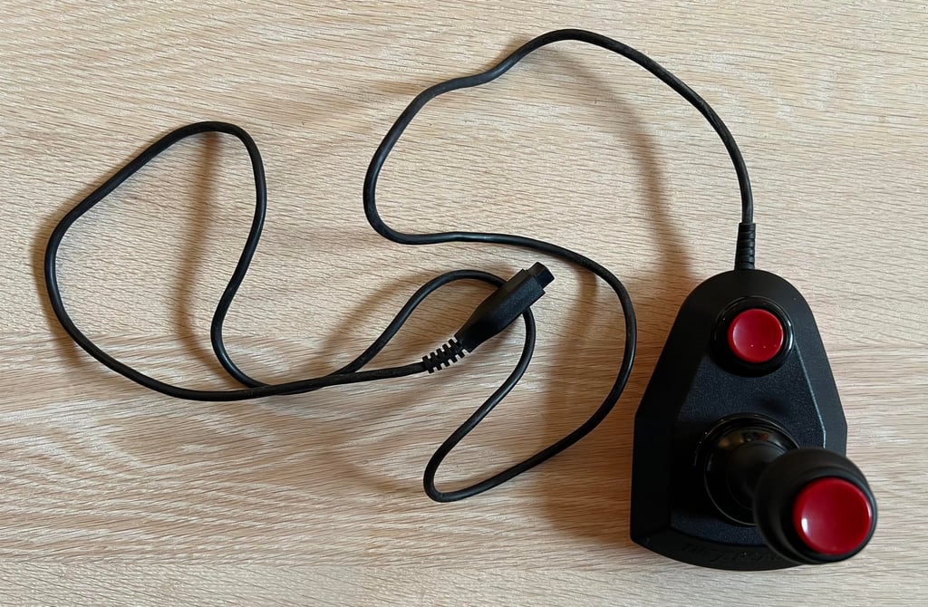
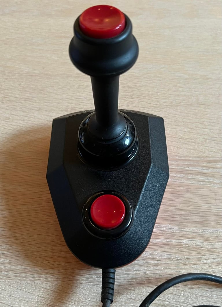
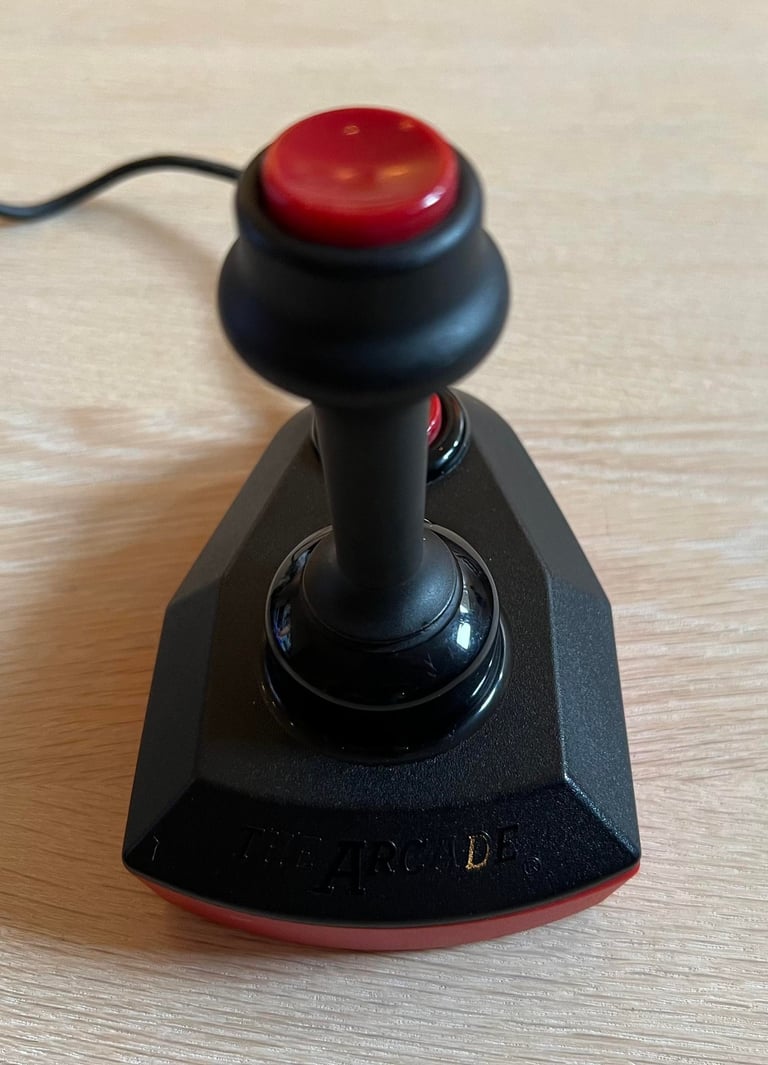
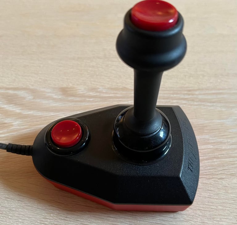
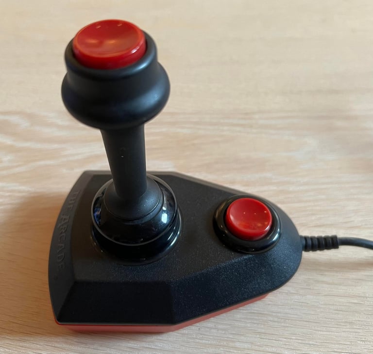
The Arcade joystick. One of the best quality joysticks for the Commodore / Amiga machines in my opinion. And the "Turbo" version with the additional fire button on top of the joystick shaft to really push it to the limits... Nice!
This Arcade Turbo joystick is in quite good condition. It is in a quite overall dirty state, and the fire buttons and shaft is in need for some lubrication. But it appears to be mechanical ok: I can move all parts and also hear the neat clicking sound when moving the joystick in all four directions.
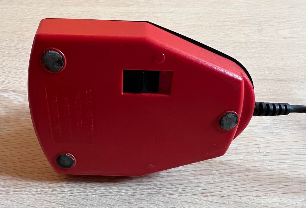
It is not easily noticeable in the pictures below, but the top cover is not properly aligned with the bottom cover. There is a 1-2 mm displacement between the covers. If you look closely on the picture from underneath you will see that the left side of the top cover is slightly misaligned to the red bottom cover. Also, but I am not 100 %, it appears to be a small subtle crack in the front of the joystick - where the cable enters the joystick.
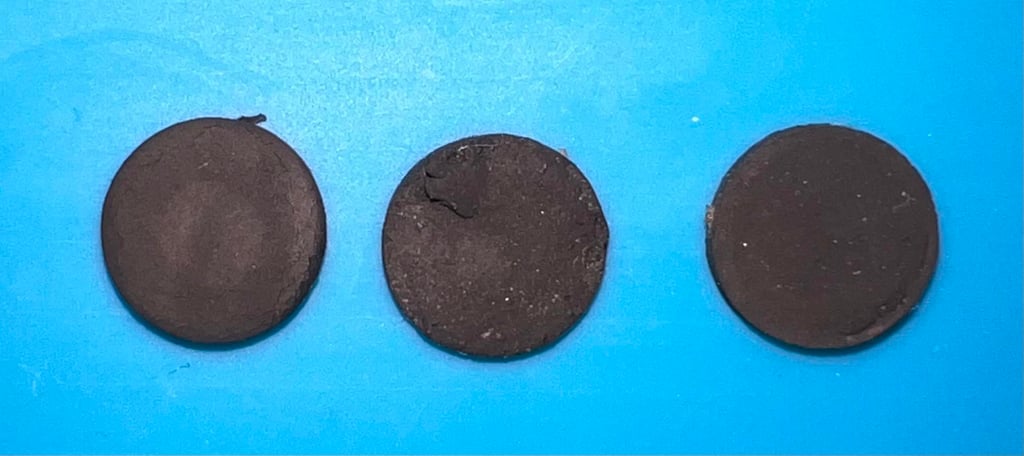
The three rubber feets are very dirty. I am not sure if they are damaged (like in dried up), but there are definitely in need of some cleaning.
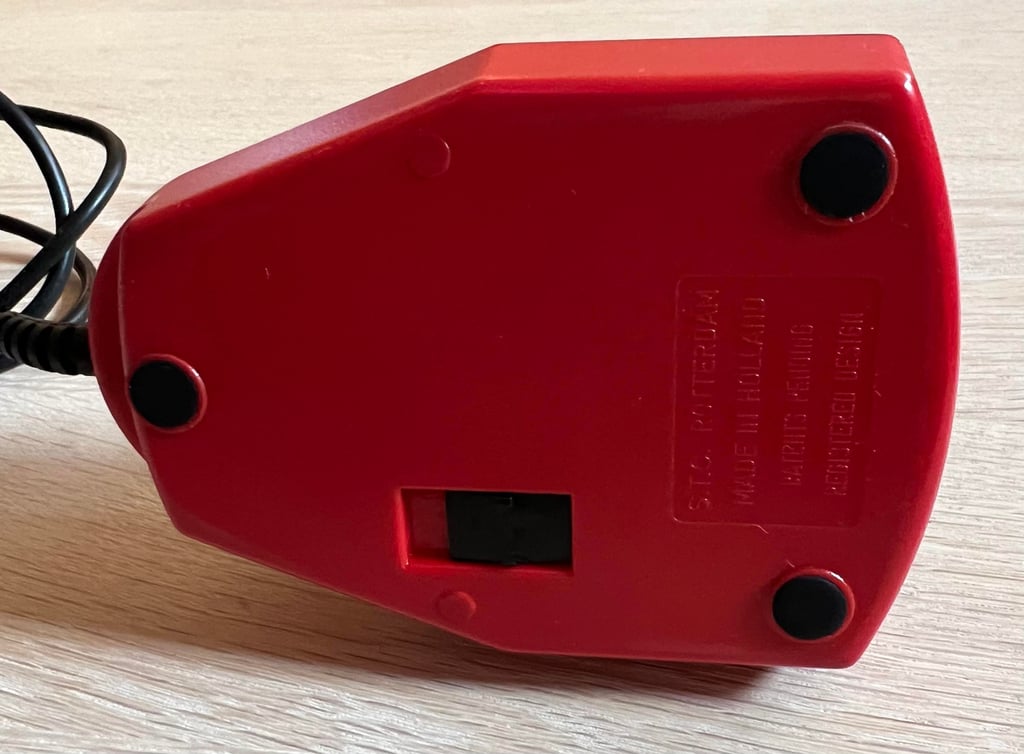
There is a switch on the backside of the joystick. This one is used to select which of the fire buttons to be used (aka the TURBO button). This button feels quite hard to push, but I am not quite sure if this is the way it is supposed to feel or not. I will look into it anyway.






Refurbishment plan
To refurbish this joystick the plan is to do this trough the following steps:
- Clean, and remove stains from, chassis and all parts (and repair if required)
- Lubricate moving parts
- Clean and check the microswitches (and repair if required)
- Check connectivity (and repair if required)
- Verify joystick operation by testing
Disassembly
The joystick consist of a top- and bottom cover which are screwed together. But where are the screws?! Fear not! They are beneath the three dirty rubber feet:-)!
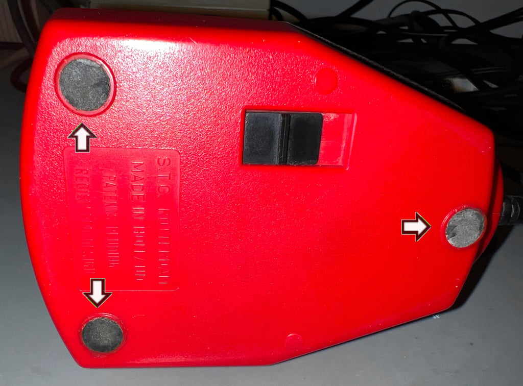

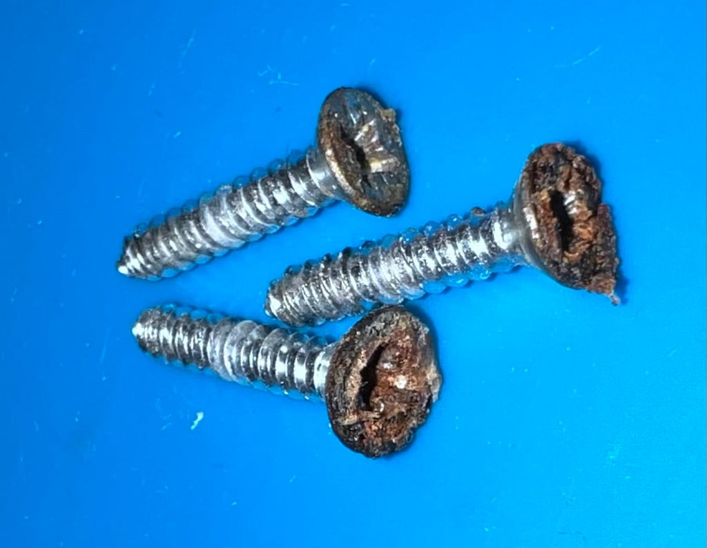
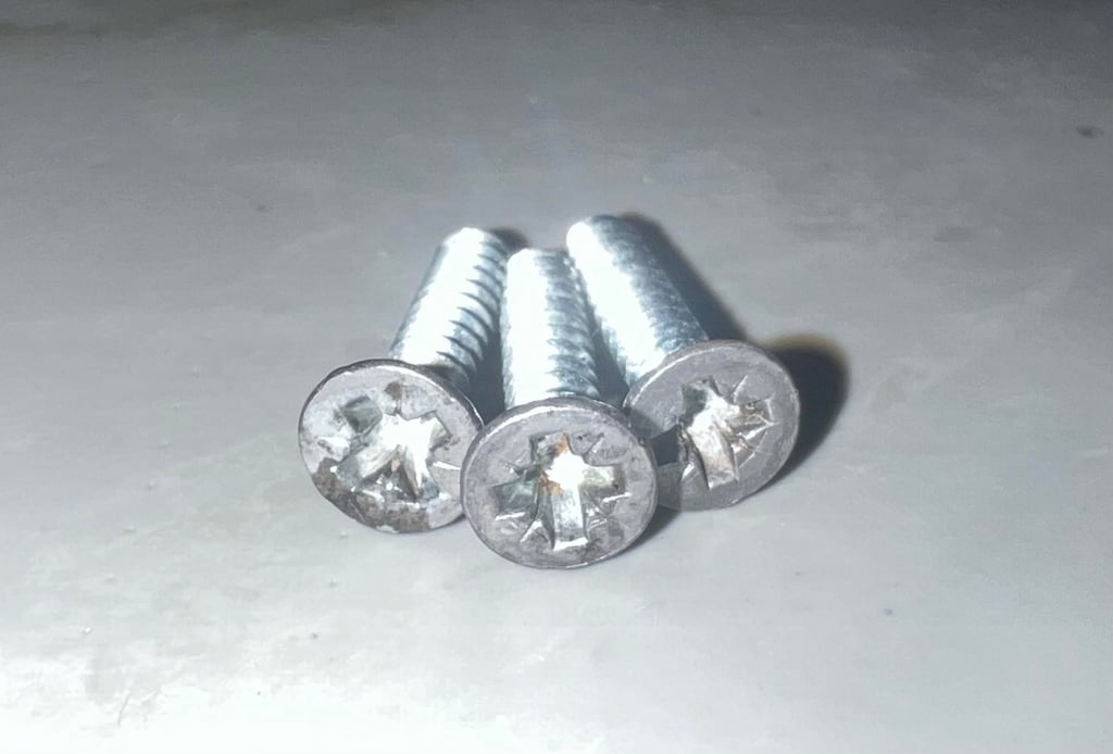
To remove the rubber feet a small, thin flat screwdriver is poked beneath the feet. It is important to be very careful to avoid damaging these rubber feet. With the rubber feet out of the way the three screws are revealed. As can be seen from the picture below they appear to be rusted!
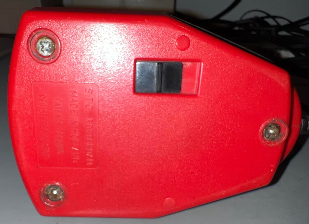

Close up of the screws. Can they be refurbished?

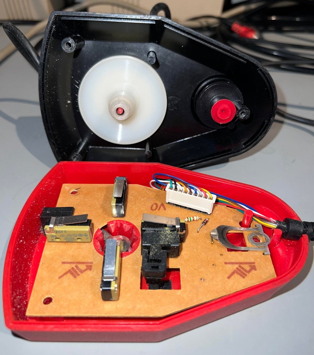
The top cover is lifted away from the bottom. And there is also a small "snapping" sound which could indicate that the top- and bottom covers aligned for a brief moment. As can be seen from the picture below the interior is in quite good condition. There is some dirt and grease, but it appear to be intact and undamaged.

This is where I choose to stop the disassembly. It is not possible (as far as I know) to disassemble the fire button and shaft without risking damage.
Exterior casing and plastic parts
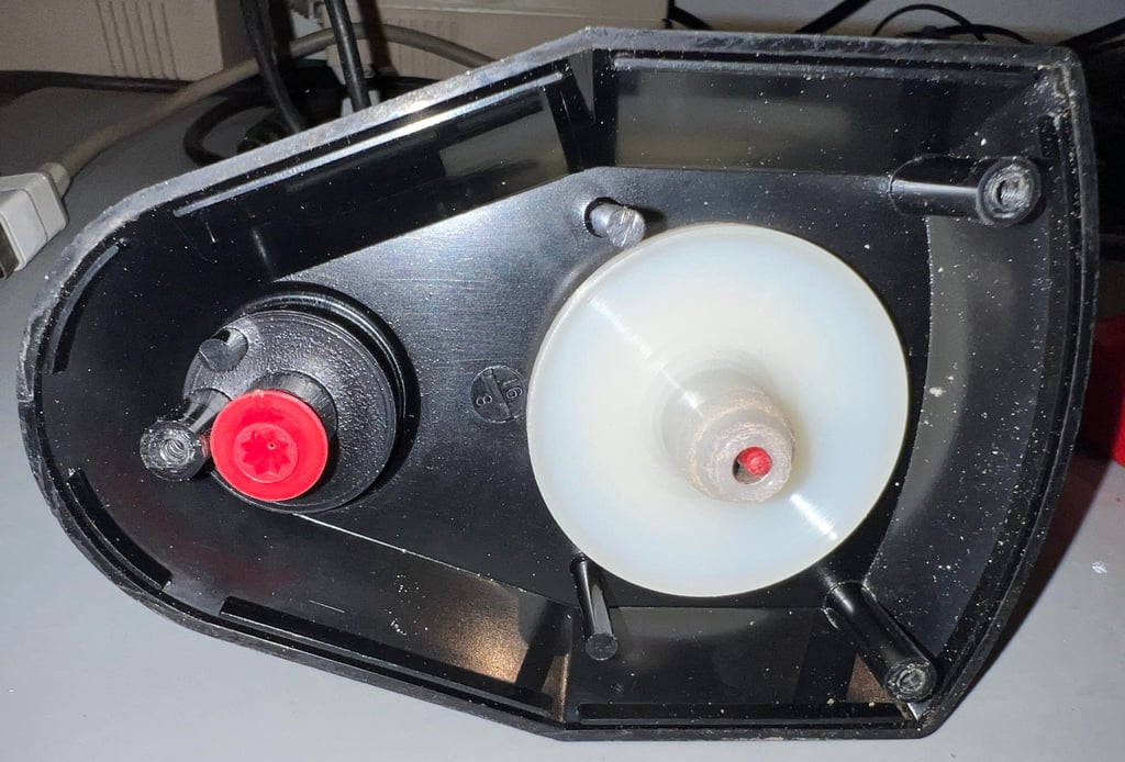
The top cover appears to be in fine condition. From the pictures presented in the "Starting point" there are only some dust and grease on the top cover. And the inside is just the same - as can be seen from the picture below.

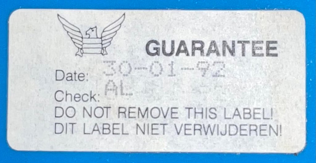
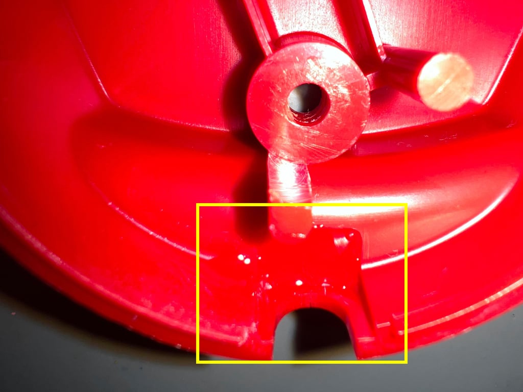
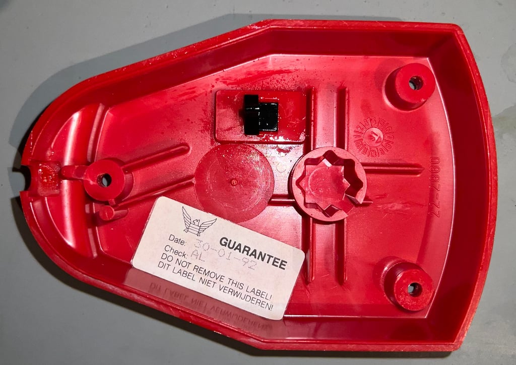
The bottom is also in good general condition, but there is a very thin crack where the cable enters (strain relief area). It is not so easy to see in the picture below, but the left arrow indicates this area. Also, the toggle switch which is quite stiff appear to be ok, but lacking some lubrication (see right arrow). And the most cool thing: THE ORIGINAL SUZO WARRANTY SEAL. As can be seen from the picture the joystick got its seal Thursday, 30th January 1992 by "AL" - probably a nice person from Rotterdam.
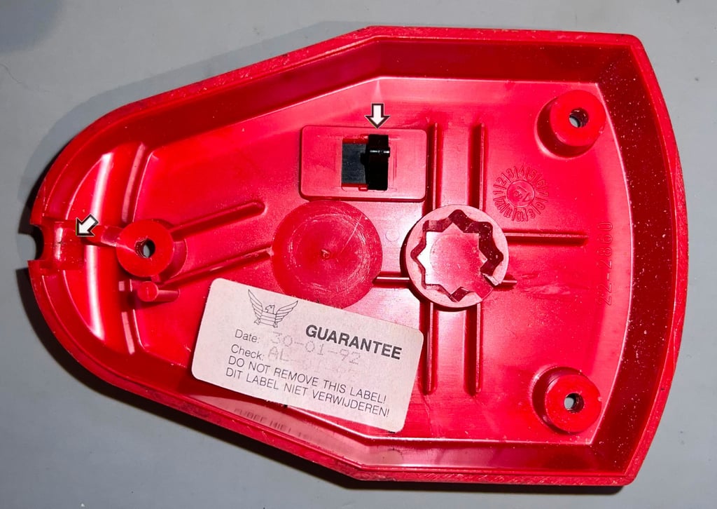

Before the covers are cleaned the warranty label is carefully removed. With the use of some hot air from a hair dryer the label is carefully removed with a pair of tweezers.

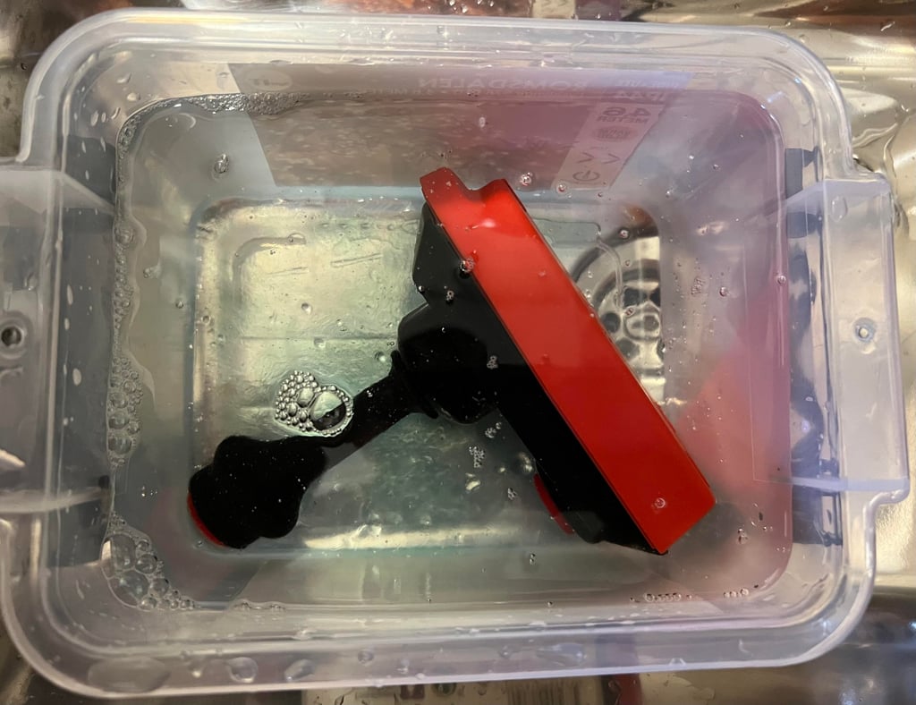
Both the top- and bottom covers are placed in a box filled with mild soap water. Also, the three rubber feet are put in the box with the covers. All parts are submerged in the soapy water for about 48 hours. This removes most of the dirt and grease.

After cleaning and drying the bottom cover, the small area with the crack is covered with super glue from the inside. This should strengthen the area, preventing further damage. And also, since the glue is now on the inside there is no visible trace of the glue on the outside. The glued area is shown in the yellow square in the picture below.

A mix of this machine sewing oil and silicone spray is smeared on the plastic toggle switch (fire A/B selector). This seems to loosen the switch quite a lot. Nice! Finally, the warranty seal is put back in using some double sided tape.

Lubricating the top cover (fire buttons and shaft) is a bit messy. Using the same combination of thin machine sewing oil and silicone spray all moving parts are lubricated. To make sure that the oil do not enter the interior (to a large extent) the cover is left to dry (and soak up) for about 24 hours.
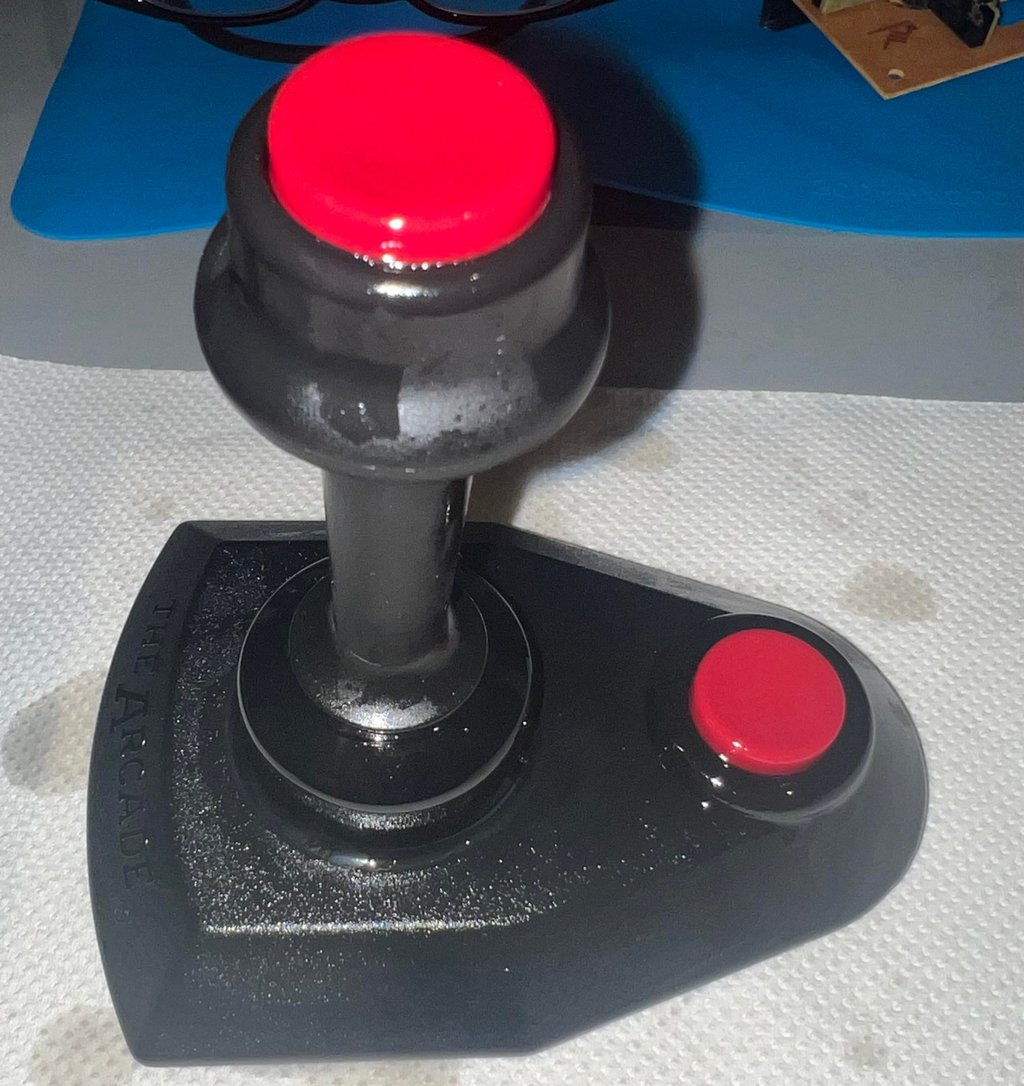

The rubber feet also turn out to be way better after a long bath. They are a bit weared from heavy use, but they look so much better now.

Luckily, the screws are not damaged by corrosion. With the help from some isopropanol and a steel brush the screws look much better - only some slight miscoloration. They are not perfect, but they are original and will last for many years to come.

Electronics and microswitches
This is the "22-2631" version of the PCB which contains a resistor and a diode. There are, as far as I know, two versions of the PCB for the Arcade Turbo; the "22-2630" and "22-2631". The former contains only one resistor and the latter contains an addition diode. As discussed in a refurbish of a similar Arcade Turbo, I still do not understand why Suzo did this. The anode side of the diode is connected to pin #9 (Pot Ax) and the catode to +5VDC. See hand drawn schematics below.
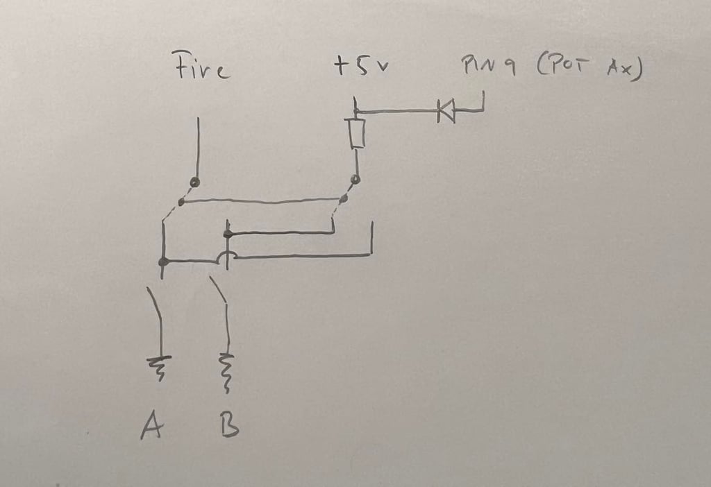

The PCB is thoroughly cleaned on both sides with isopropanol. And all four microswitches, and the two other switches, are sprayed with contact cleaner. See pictures below.
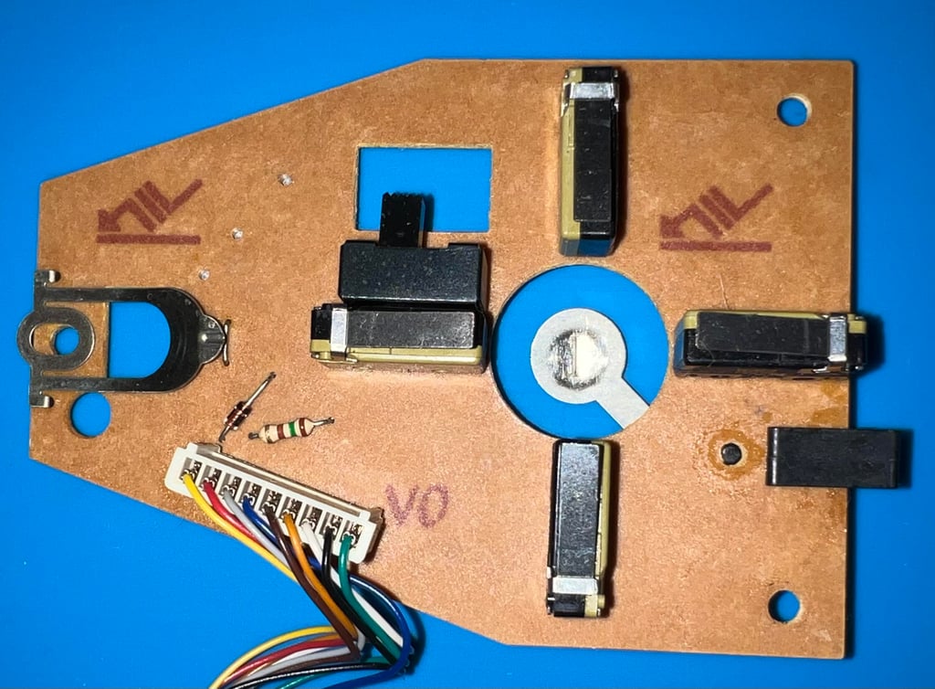

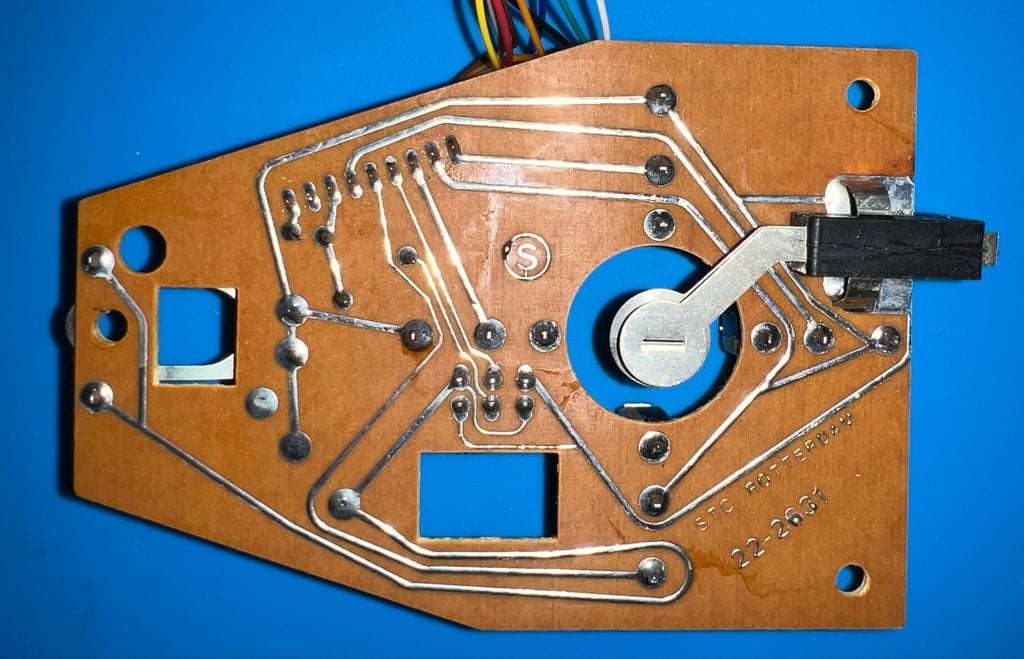

I notice that the plastic bracket holding the fire button (for the shaft) is slightly tilted. Is is probably not a problem (and we know that "AL" has checked this!), but I will investigate this.
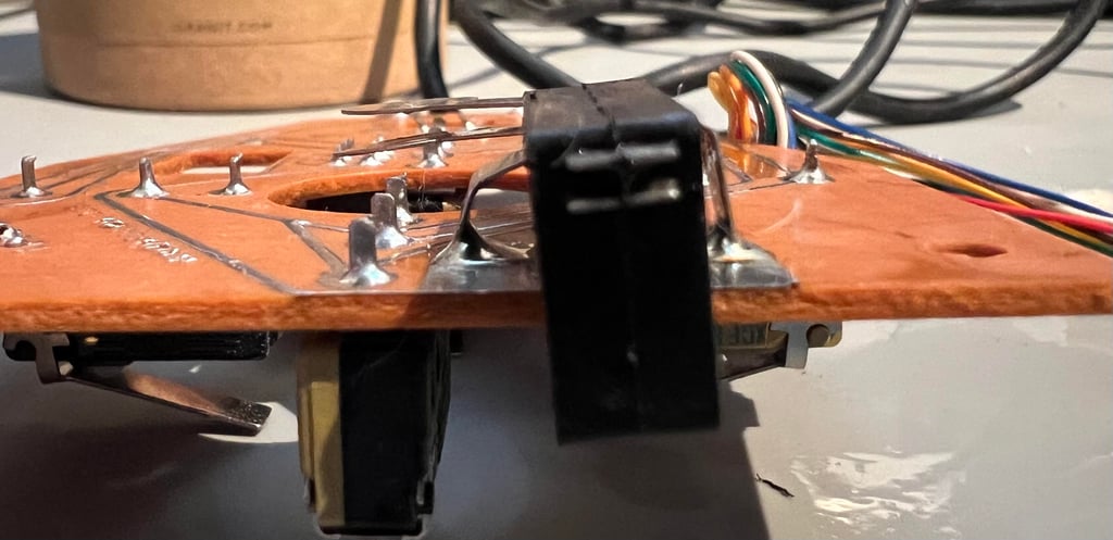

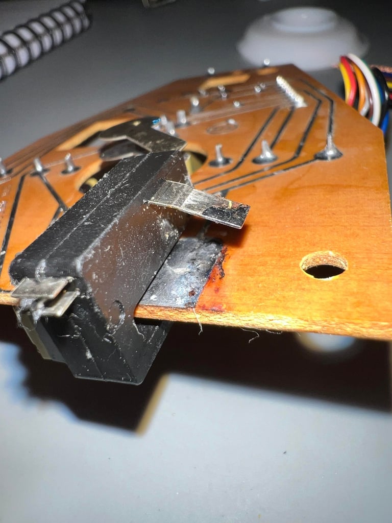
The right hand side of the bracket is desoldered. But it turns out that the bracket is not only soldered to the PCB it is also glued to the PCB (there are some very small pins beneath the bracket). It is not worth trying to pry this bracket in place - the risk of breaking the old, and brittle, is too high. So the bracket is soldered back in place. See pictures below.

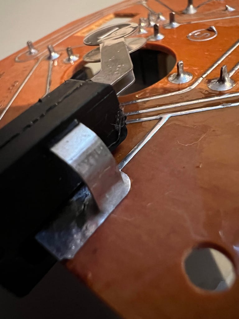

All microswitches, switches, cable and connectors are checked thoroughly with a multimeter and a self-made dongle.
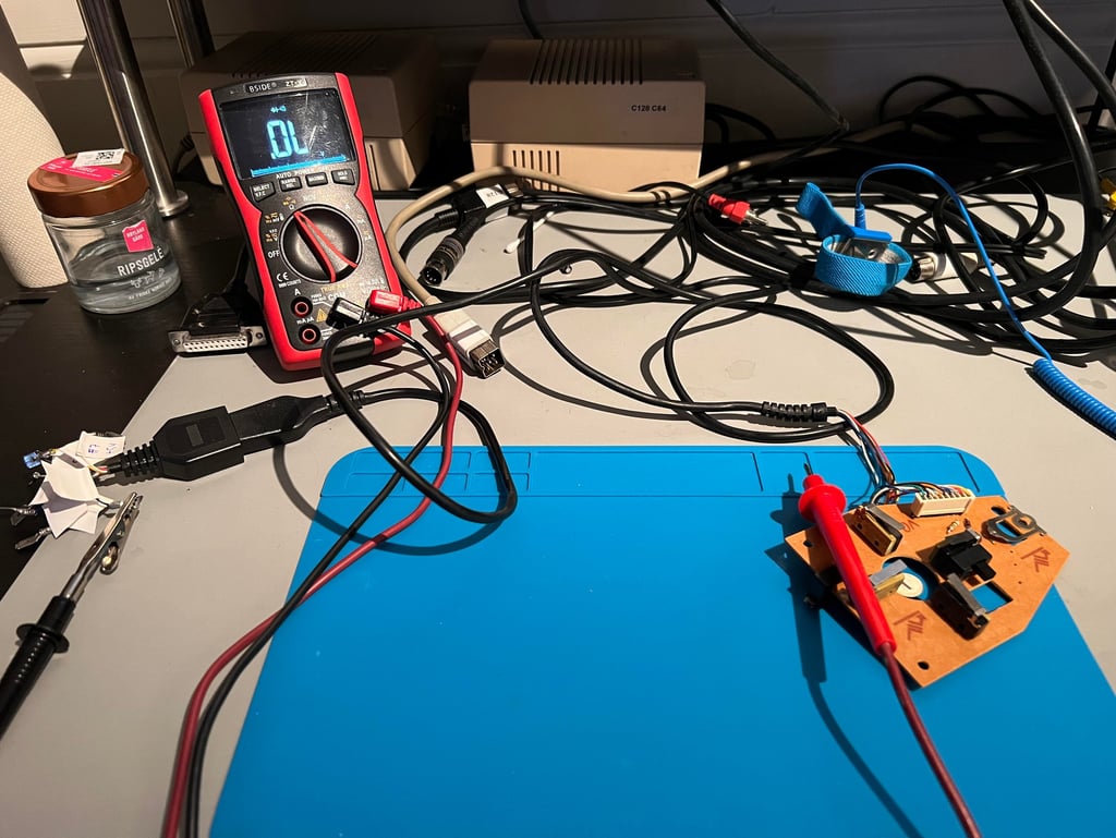

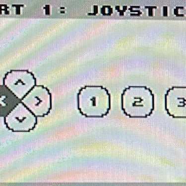
While checking the electronics I discover a fault (which I also confirm using a Commodore 64 with the joyride software):
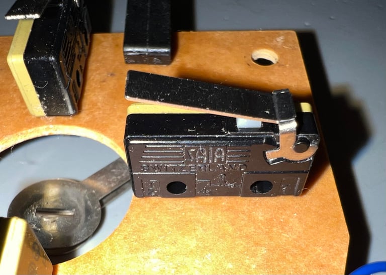
When the microswitch controlling the LEFT direction is fully pressed down the registered signal from the switch starts to "flicker". That would mean that e.g. playing a game and controlling a sprite going left it would "lag" since the LEFT signal is not provided continuously.
Repair
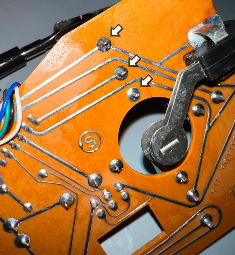
The multimeter is connected to the underside of the microswitch with some crocodile connectors. It turns out that the switch does not appear to be faulty doing this measure. This points towards a bad / dried up solder points (see arrows in picture below). The three solder points are re-soldered and the microswitch is also cleaned with contact cleaner. This fixes the problem.


Testing
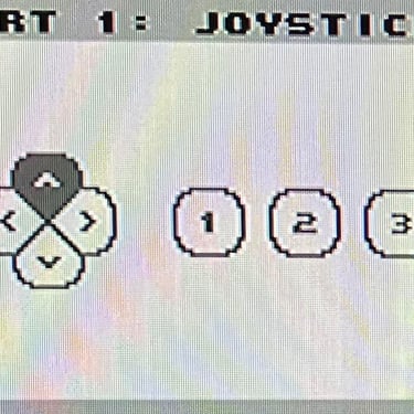
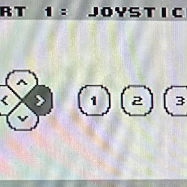
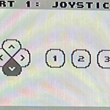
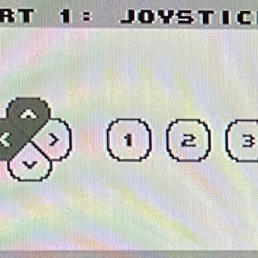
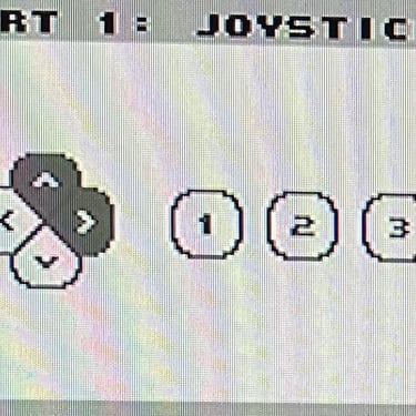
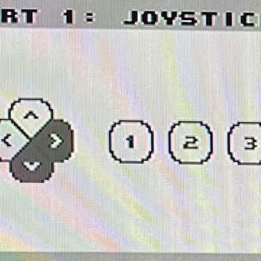
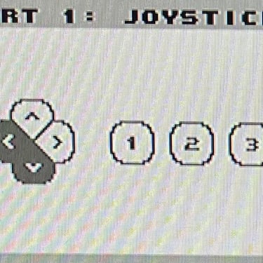
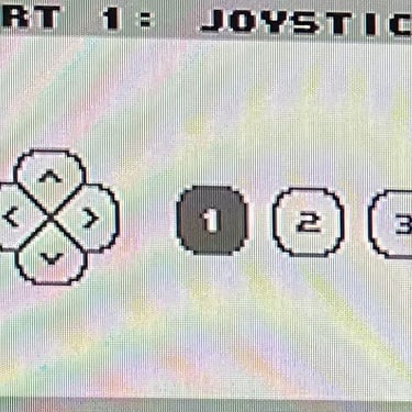
To verify that the joystick work as it should I check it with the Joyride software. Result is that all directions and fire buttons works fine works as expected. All tests pass.
Final result
"A picture worth a thousand words"
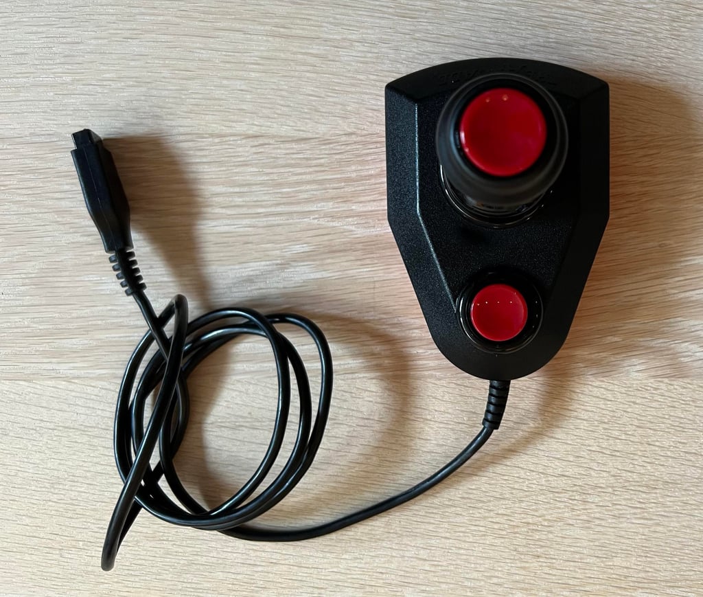
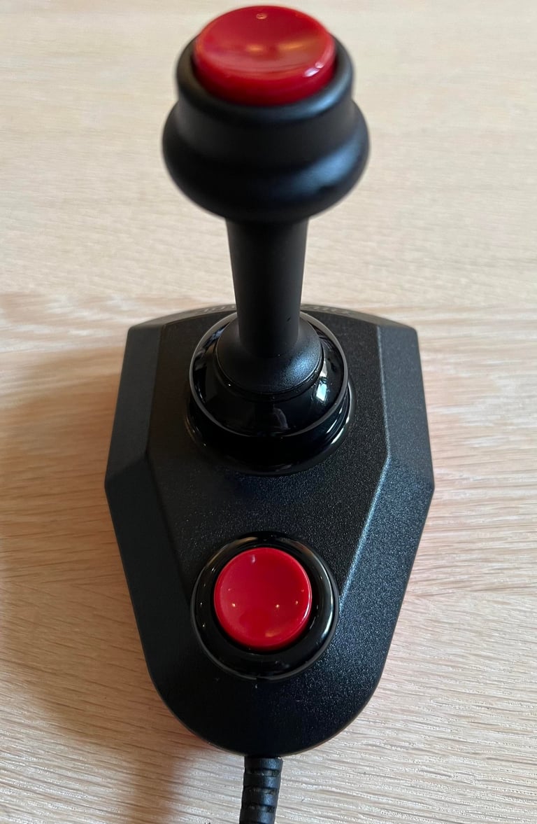
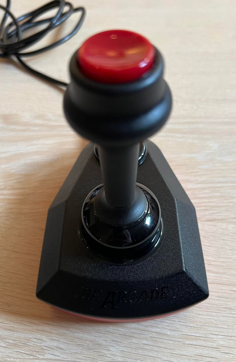
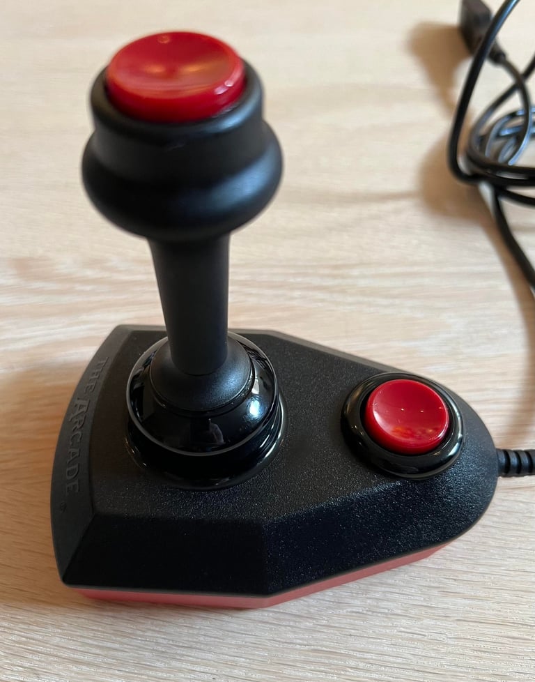
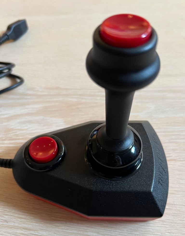
Below is a collection of the final result from the refurbishment of this Arcade Turbo joystick. Hope you like it! Click to enlarge!






Banner picture credits: SdeVries
