
The Arcade
Starting point
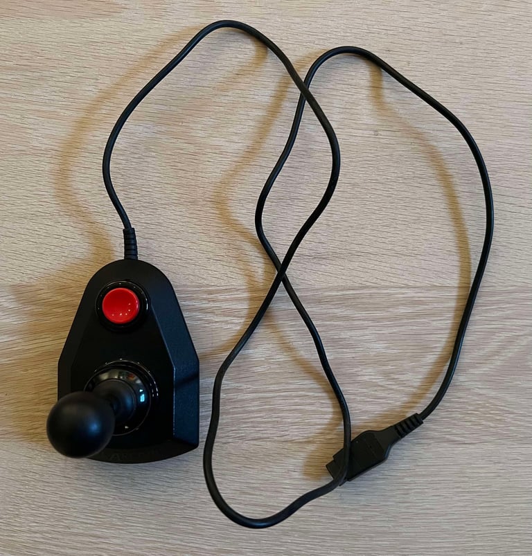
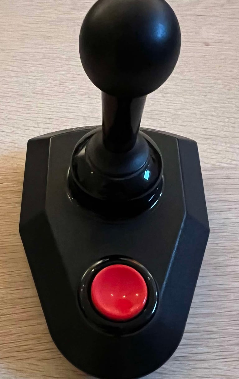
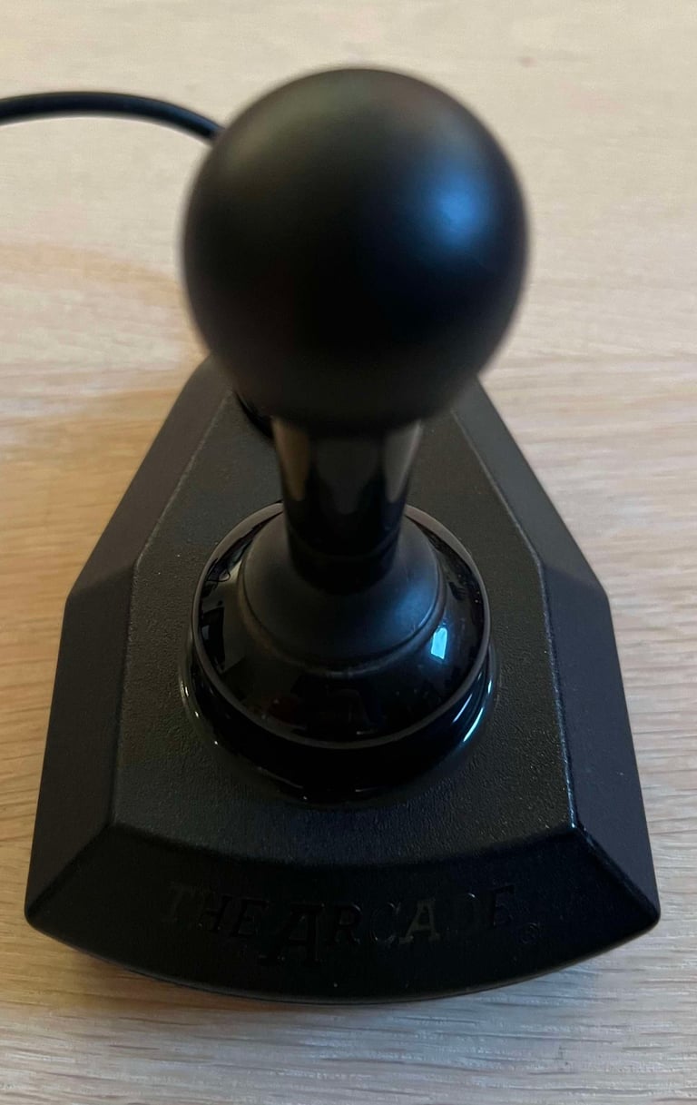
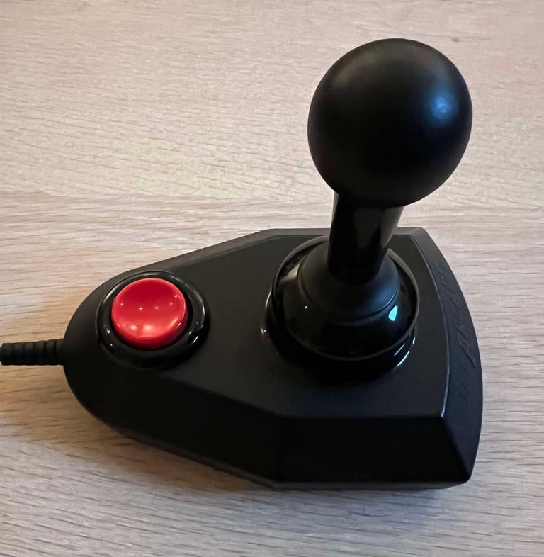
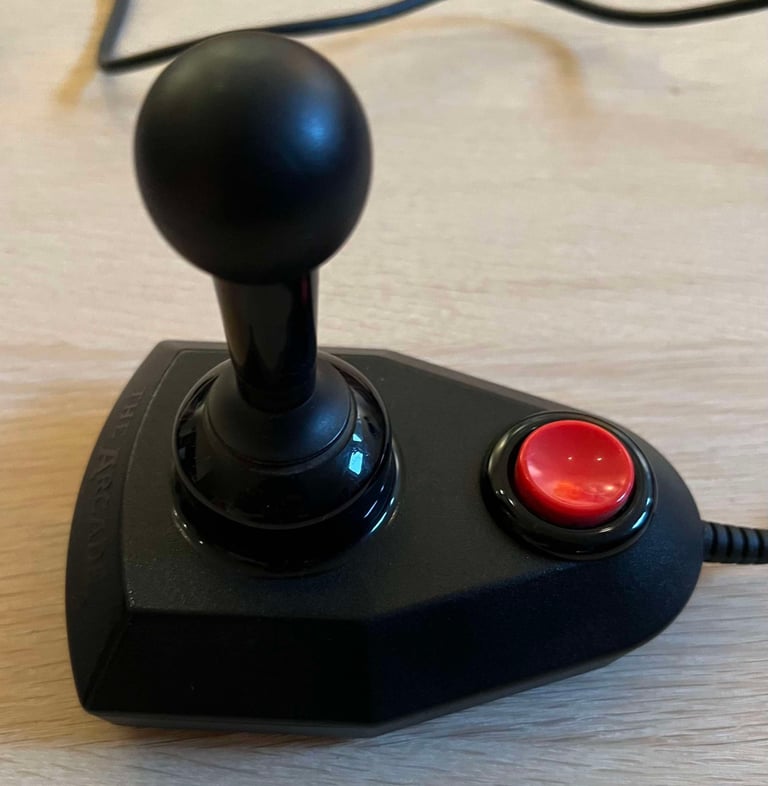
The Arcade joystick is very nostalgic to me. It was the first joystick I ever had on my Commodore 64. This joystick to be refurbished is not my old one, but it looks VERY good!
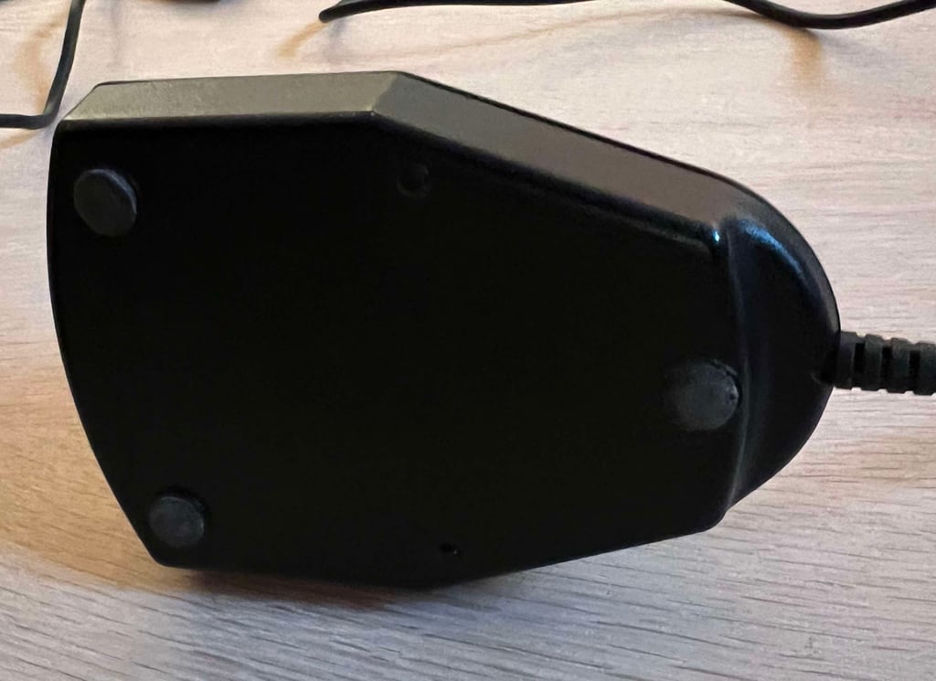
There is quite some grease (not very visible in the pictures) between the base and the joystick shaft, and also between the fire button and the shaft. The sound coming from the four directional microswitches (UP/DOWN/RIGHT/LEFT) sounds promising, but the FIRE button feels a bit "sticky". On the front of the joystick, just beneath the cable strain relief, there is a very tiny crack (or missing piece) - but this is really marginal. On the bottom cover there are some scratches. Or, it looks like someone has scratched in their initials ("JH").
The DB9 connector shows signs of wear, but I think it is superficial. All of the three rubber feet are in place, although they are a bit loose / misaligned.
Below are some pictures of the joystick before refurbishment.






Refurbishment plan
To refurbish this joystick the plan is to do this trough the following steps:
- Clean, and remove stains from, chassis and all parts (and repair if required)
- Lubricate moving parts
- Clean and check the microswitches (and repair if required)
- Check connectivity (and repair if required)
- Verify joystick operation by testing
Disassembly
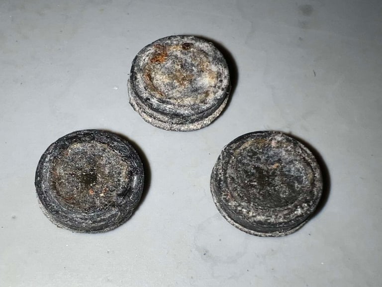
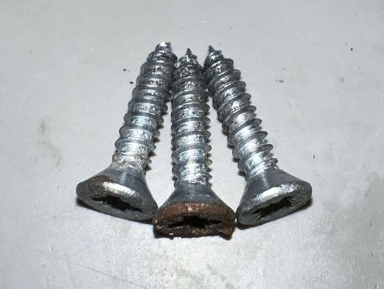
The three screws holding the top- and bottom cover together are located beneath the rubber feet. With a small flat screwdriver the rubber feet are carefully removed.
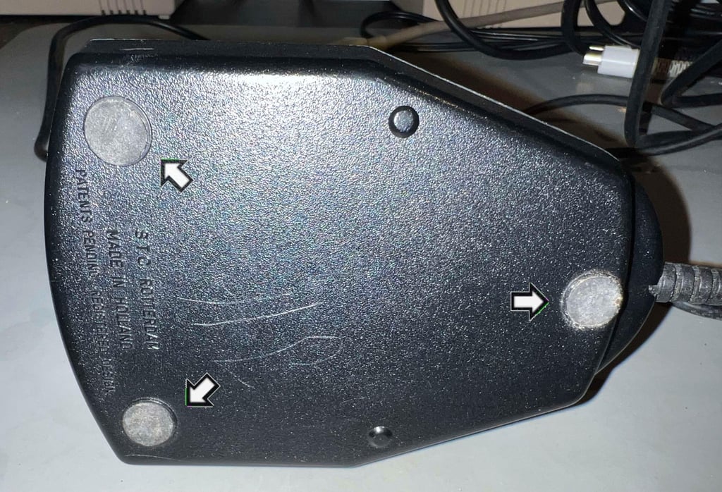

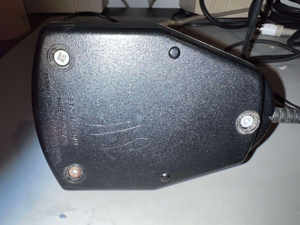

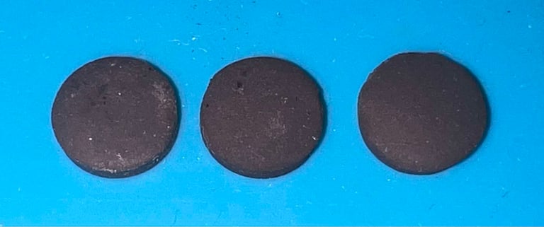
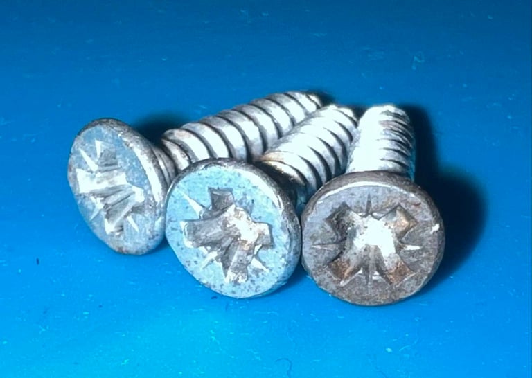
Both the rubber feet and screws are quite dirty, but appear undamaged. With some cleaning they will be as good as new hopefully. The dimension of the rubber feet is 2.5 mm thick and a diameter of 10 mm. And the screws are 3.5mm x 16 mm (from tip to top of head).


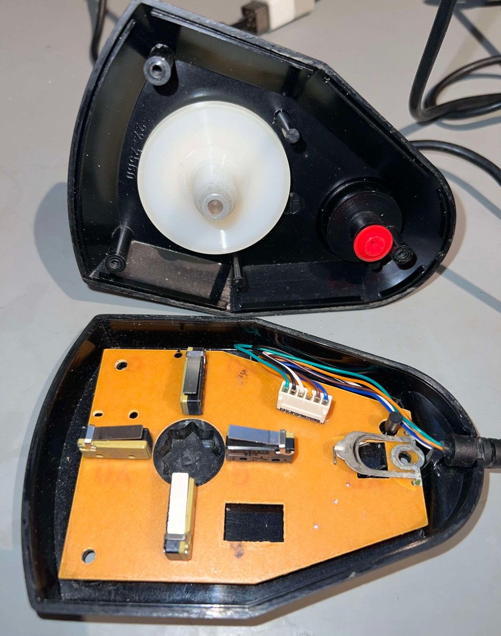
With the screws out of the way, the top cover is simply lifted off. Now the interior is exposed and it looks to be in very fine condition.

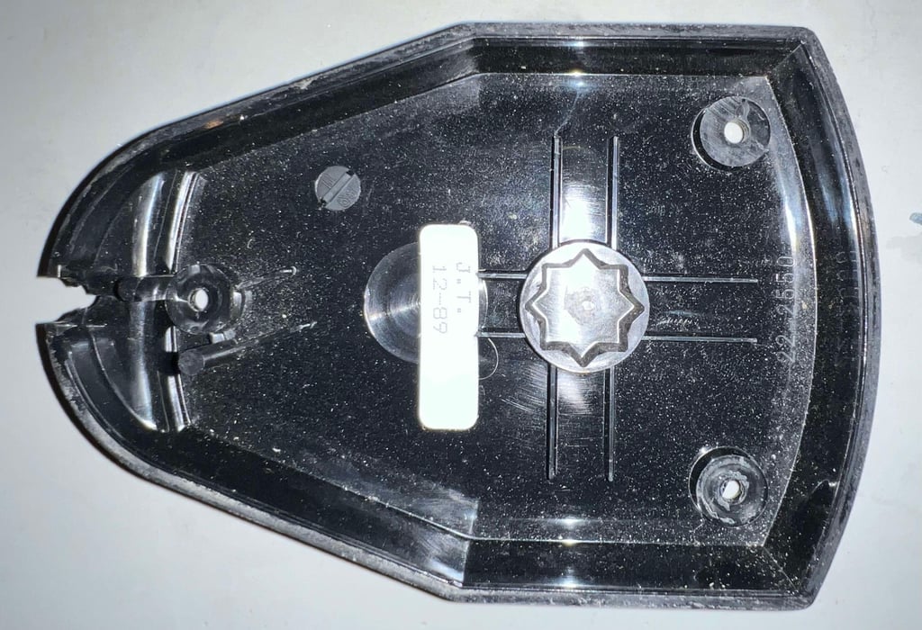
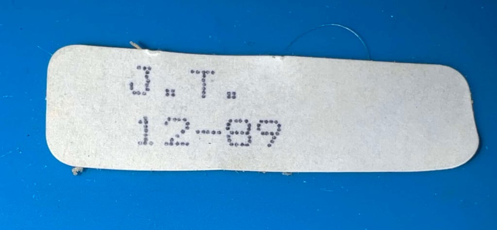
The PCB is removed simply by lifting it off the bottom cover. And this reveals something nice - a quality assembly sticker saying "J.T. 12-89". I think it is fair to guess that this means that "J.T." assembled this in December 1989 in Rotterdam. And maybe "J.T." was listening to "Do they know it´s Christmas" by Band Aid?

Exterior casing and plastic parts
Before the parts are cleaned the assembly sticker is removed. By adding some heat from a hair dryer the sticker is peeled off using a pair of tweezers.

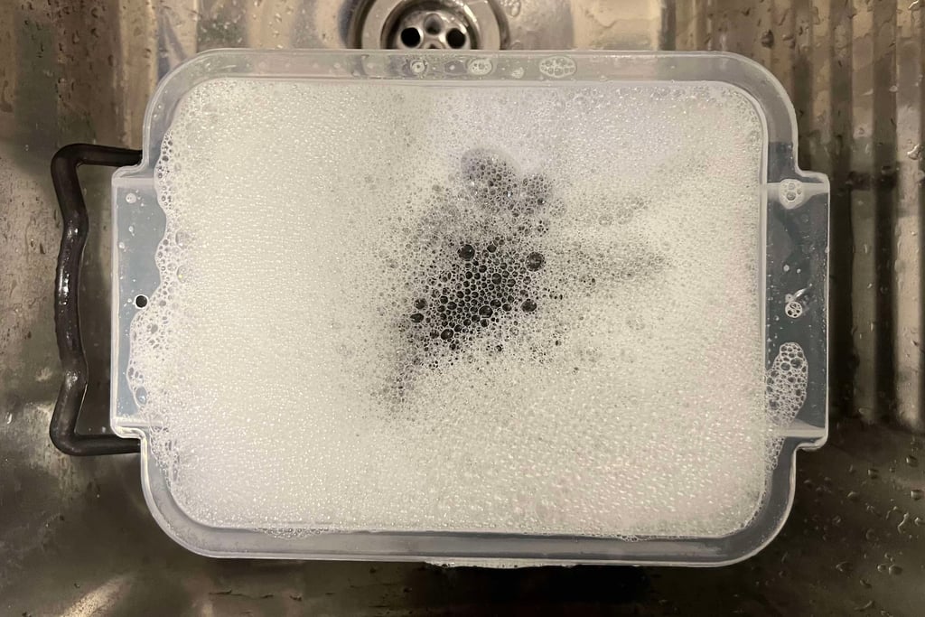
Now the parts are placed in a box filled with mild soap water for about 48 hours. This will remove most of the grease and dust.

Both the rubber feet and screws are cleaned properly. The screws are cleaned with a steel brush, and the rubber feet are cleaned with mild soap.


Electronics and microswitches
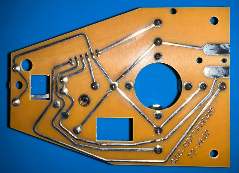
The PCB inside "The Arcade" is simple, but elegant. Equipped with four small microswitches, a leaf switch for the FIRE button and a cable connector it is both robust and serviceable. The PCB is marked "S.T.C. ROTTERDAM 22-2602". Note that "S.T.C." is an acronym for Suzo Trading Company.
There is quite some dirt and grease on the PCB, but not more than expected after 35 years...
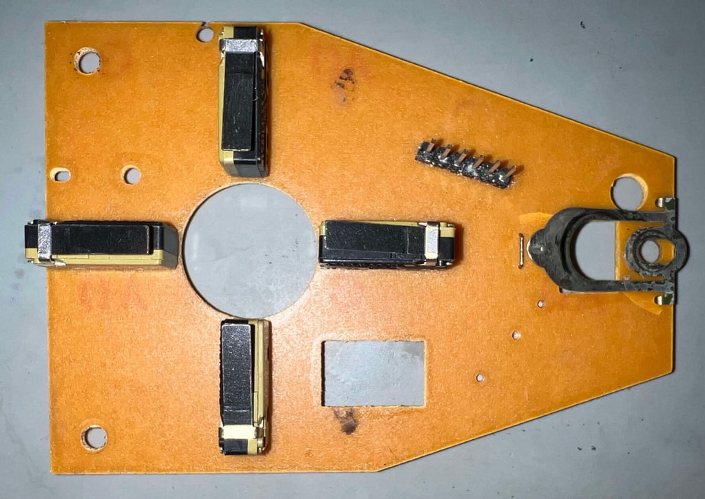

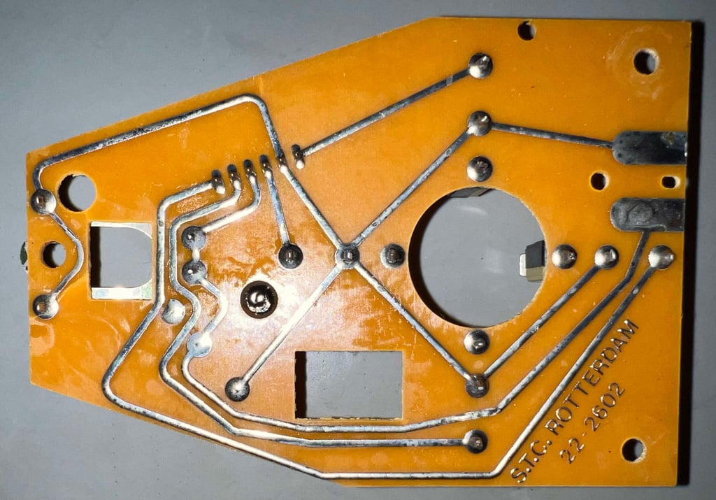

There are some marks (or even early sign of corrosion?) on some of the traces. These are removed with a glassfibre pen and isopropanol. See pictures below for a "before/after" comparison.
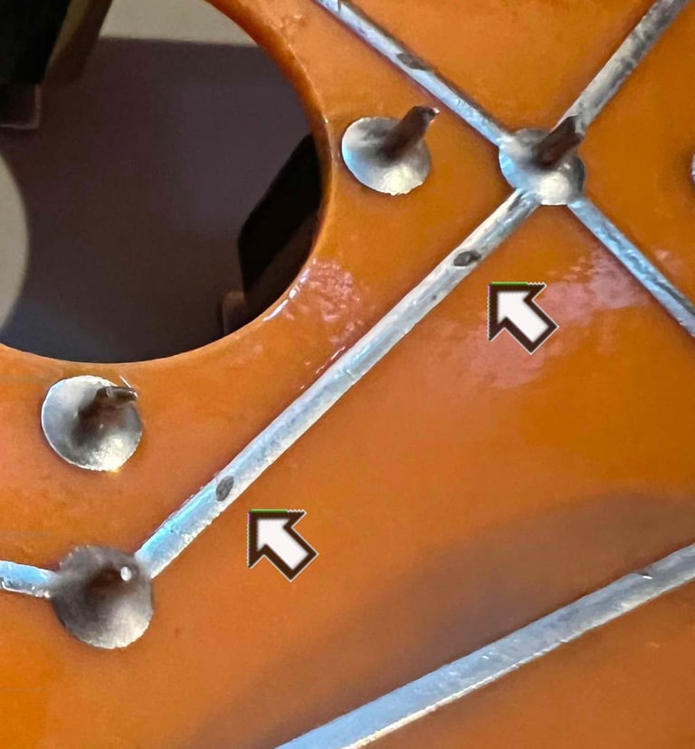

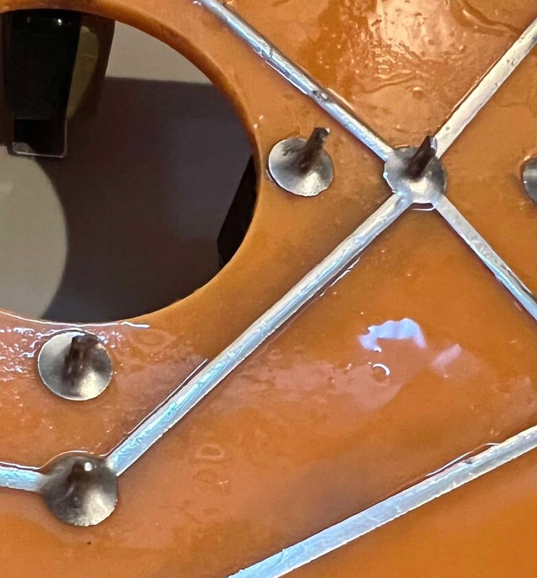

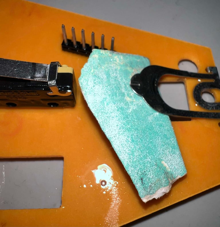
The connectivity between FIRE and GND is poor. This is repaired by carefully sanding the leaf switch and the small metal pin beneath it. Finally the whole area, and the switch, is cleaned with some isopropanol. In addition, the six pin connector is cleaned with some isopropanol and a tooth brush.

All of the four mini microswitches are sprayed with contact cleaner and "massaged". They appear to be ok already, but the contact cleaner will help on both some lubrication and internal cleaning. The microswitches used are from Landis&Gyr / SAIA model XCF8.
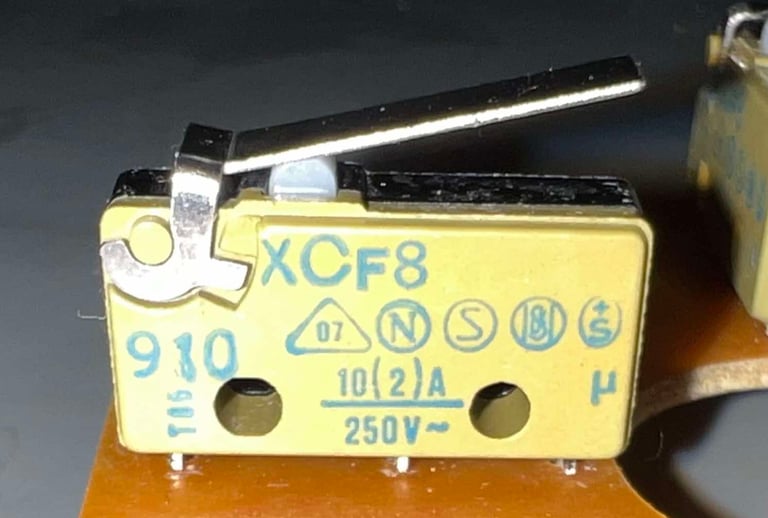

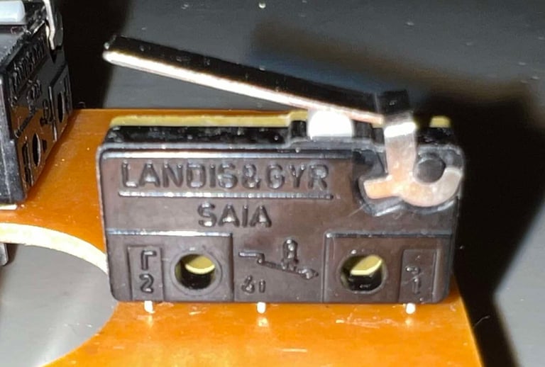

After cleaning and servicing the PCB looks as good as new!
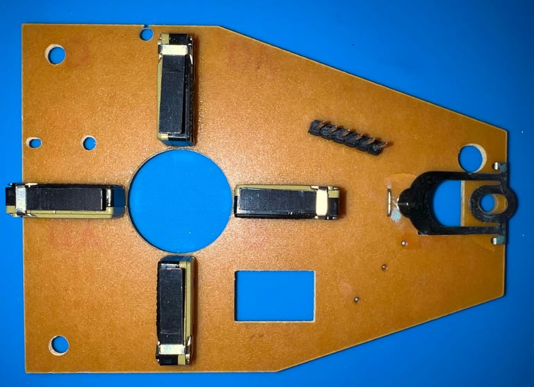


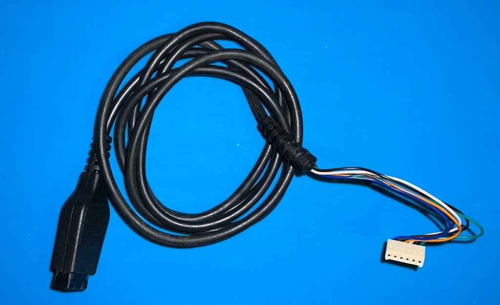
Both the DB9 connector and the 6-pin connector (to PCB) are cleaned properly with contact cleaner. Even if there are signs of use on the cable, it looks to be in quite good condition.

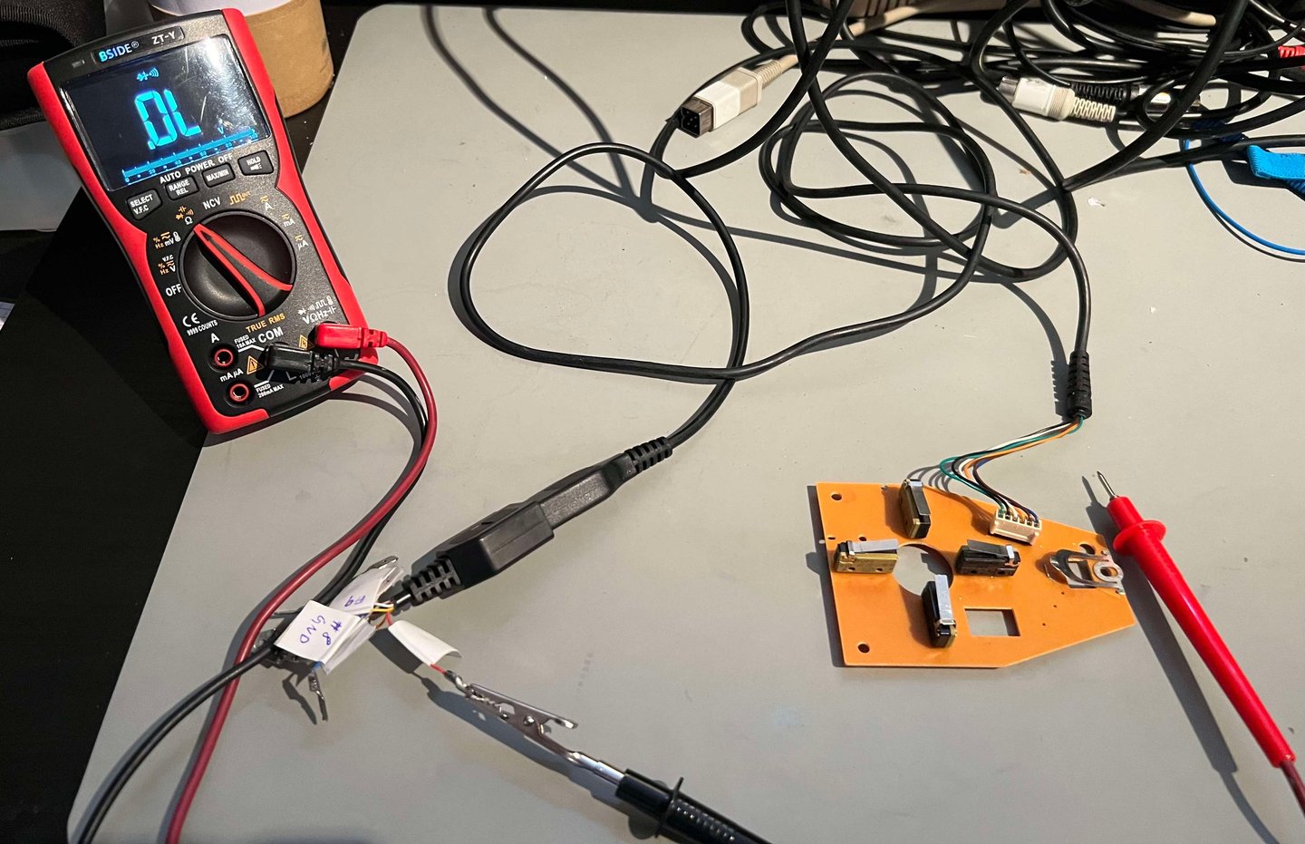
Everything is tested properly with a multimeter in continuity mode (aka diode mode). No faults or issues are detected during this testing.

Testing
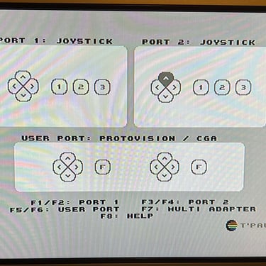
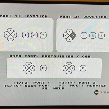
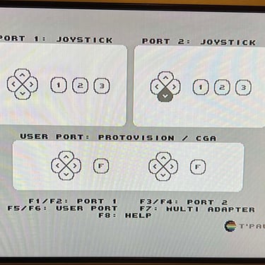
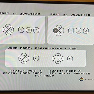
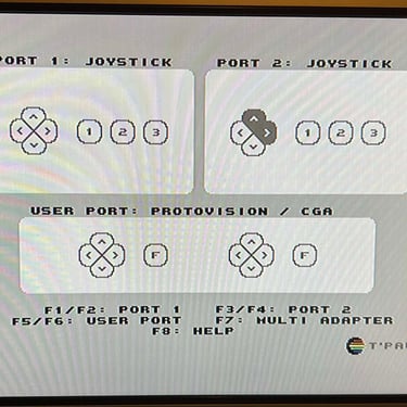
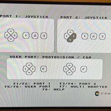
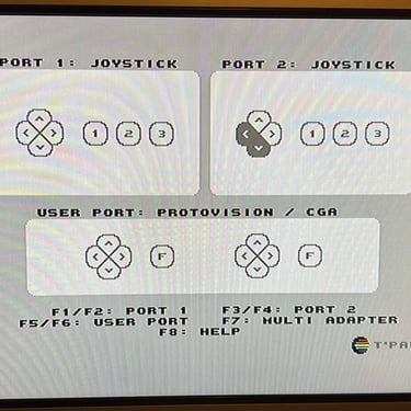
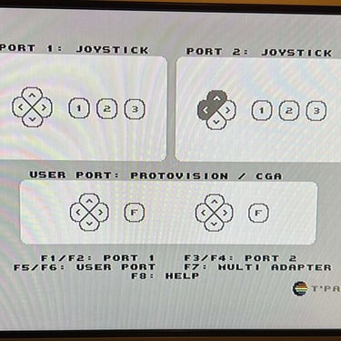
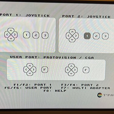
To verify that the joystick work as it should I check it with the Joyride software. Result is that all directions and fire buttons works as expected (click to enlarge). All tests pass.
Final result
"A picture worth a thousand words"
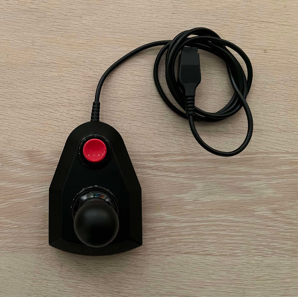
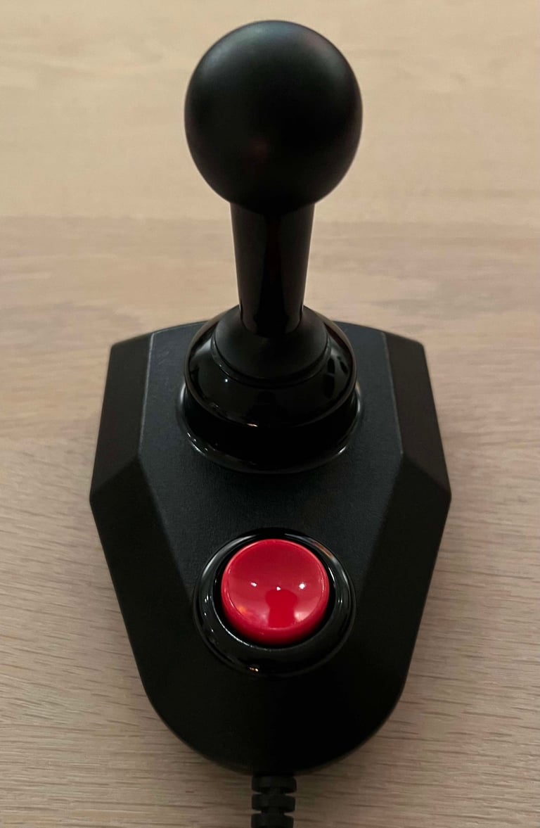
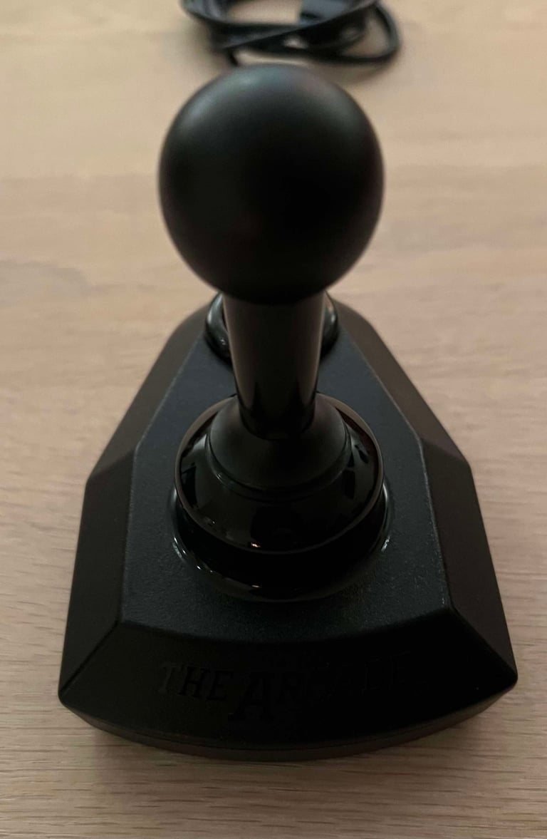
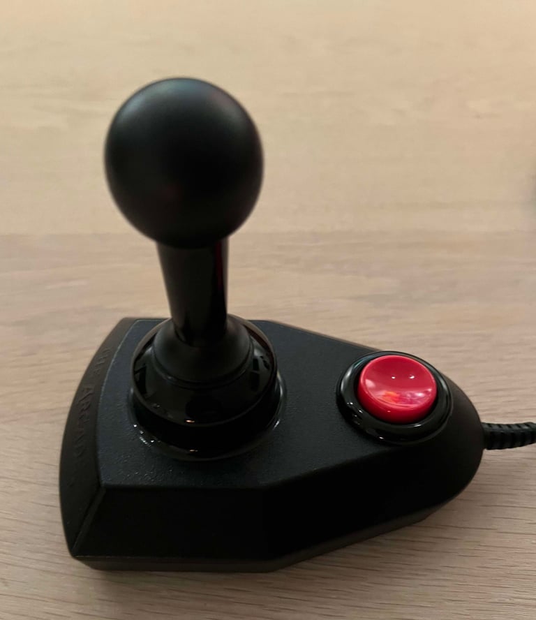
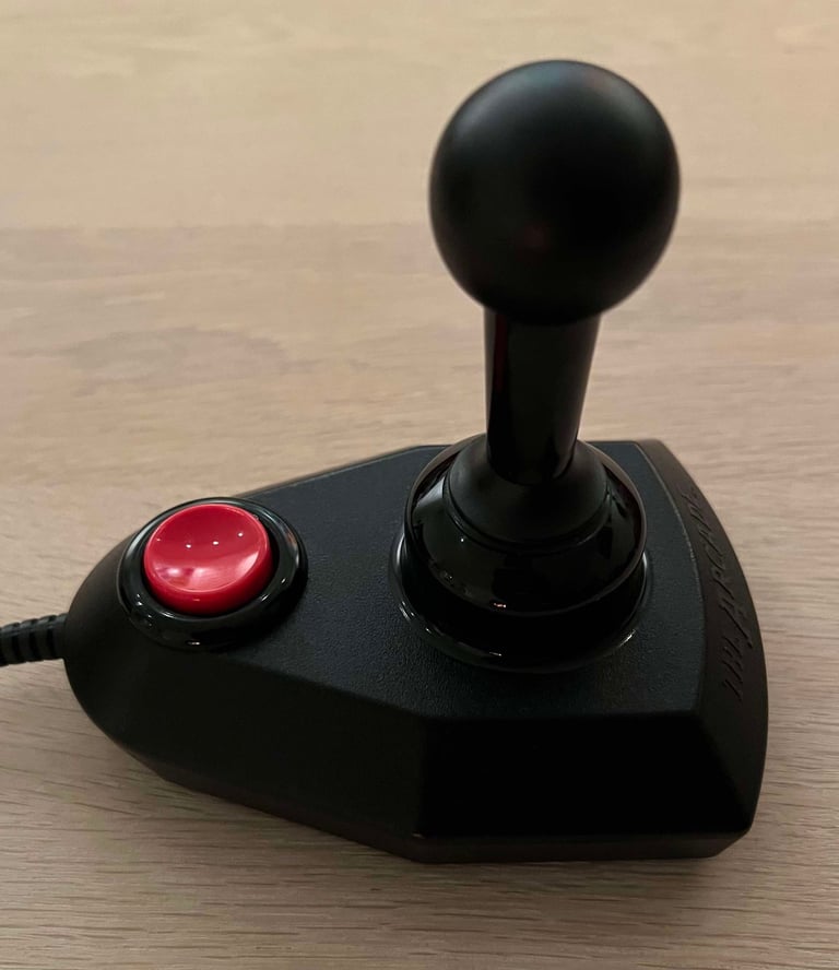
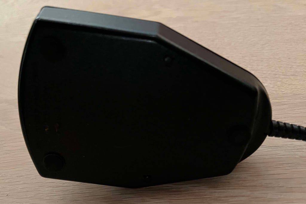
Below is a collection of the final result from the refurbishment of this Arcade joystick. Hope you like it! Click to enlarge!






Banner picture credits: SdeVries
