

ZipStik
Starting point
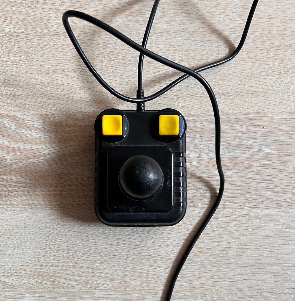
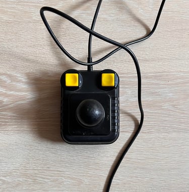
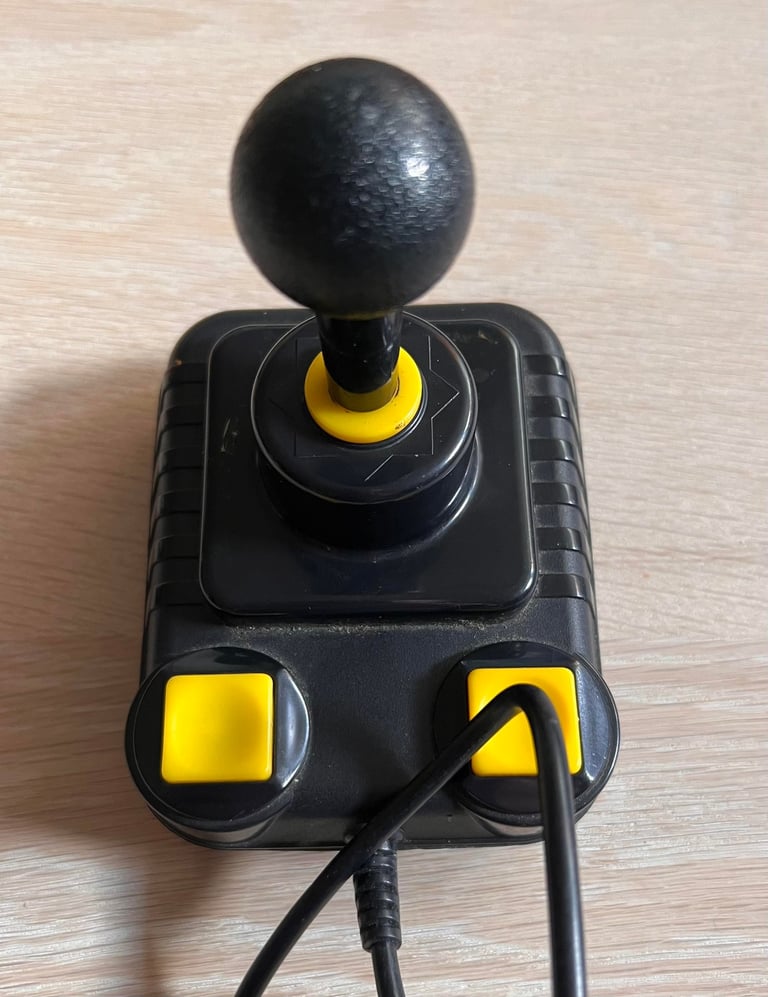
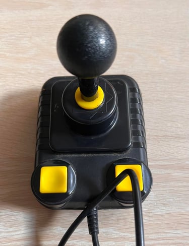
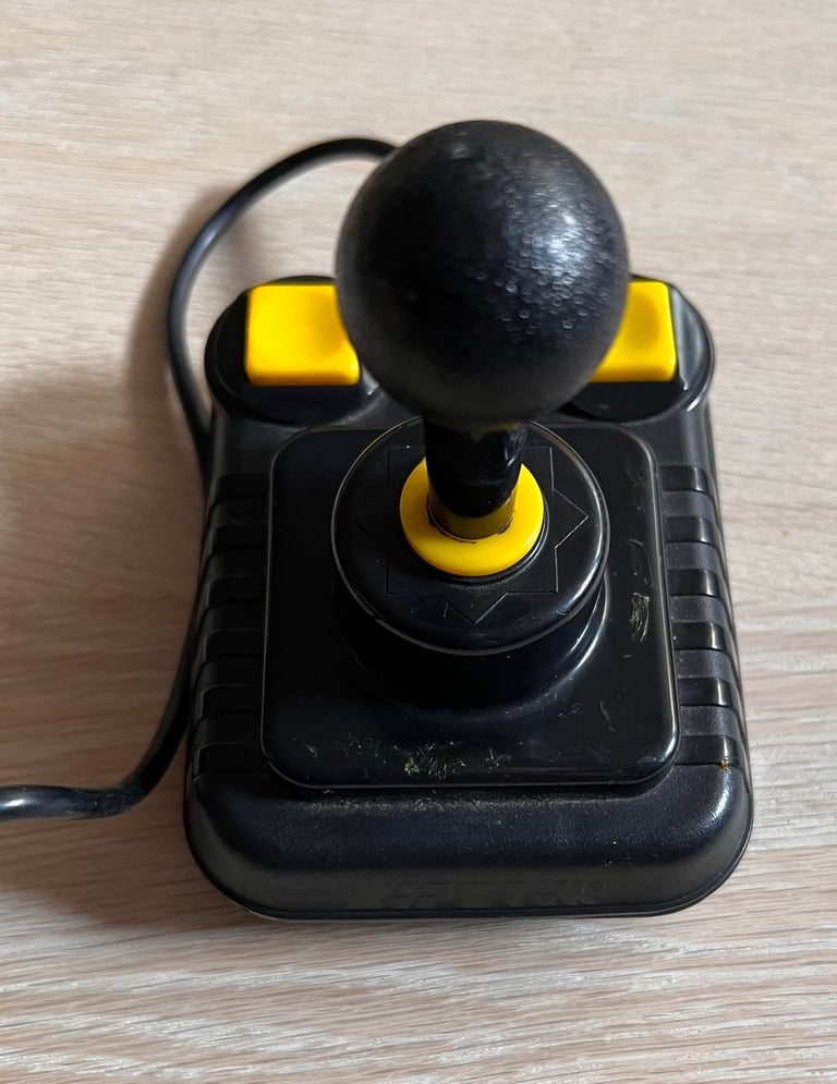
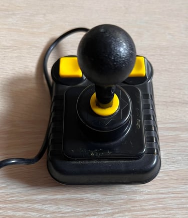
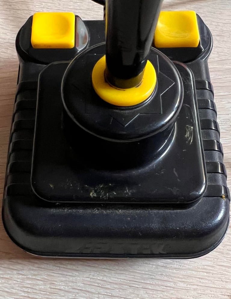
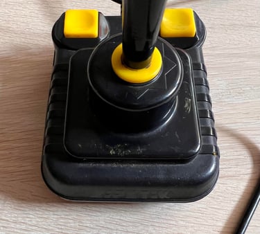
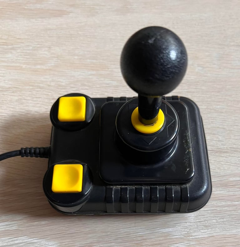
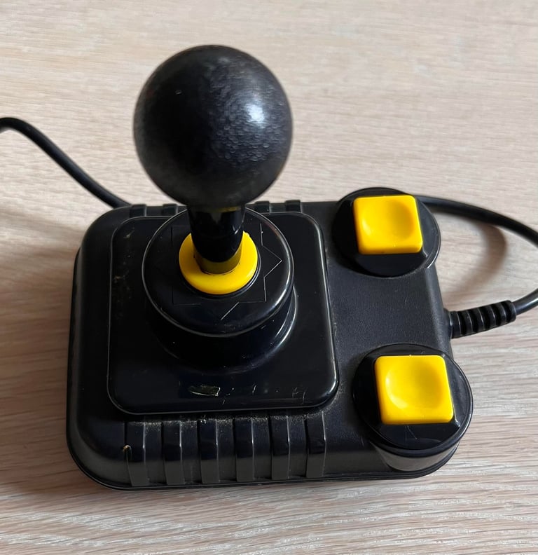
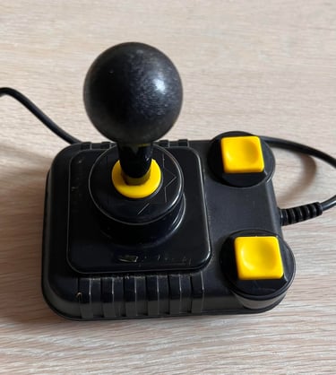
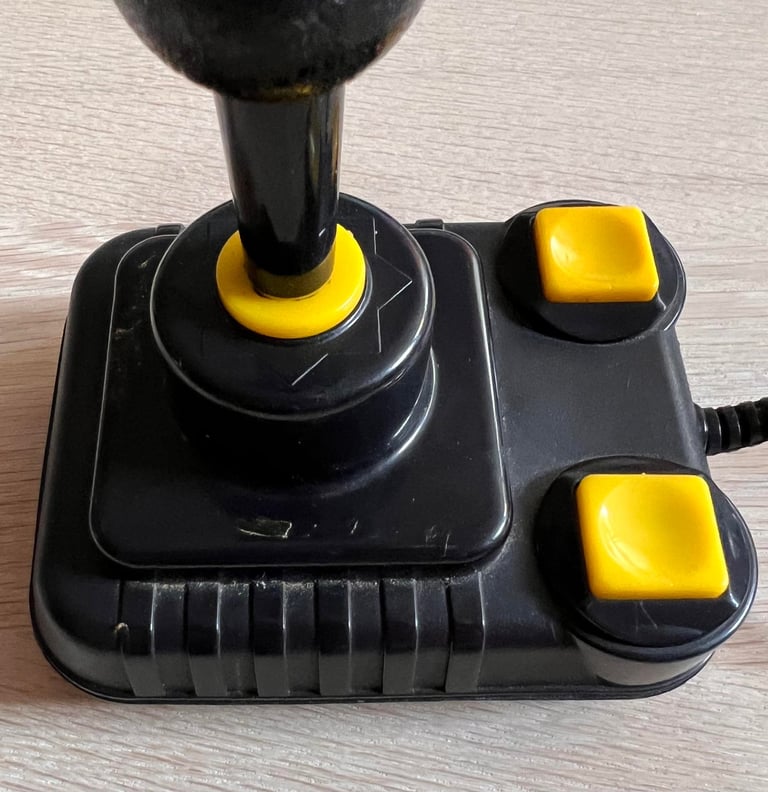
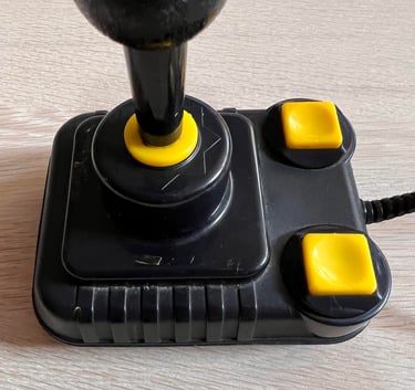
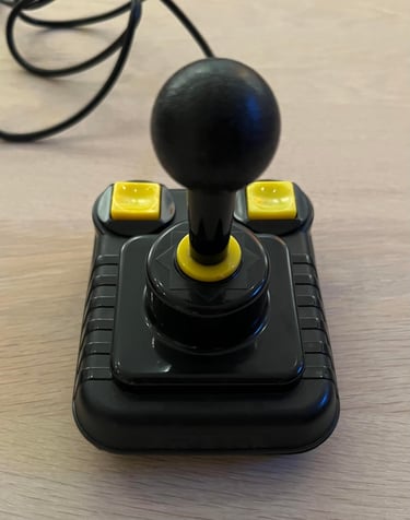
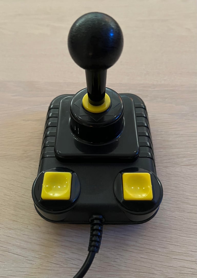
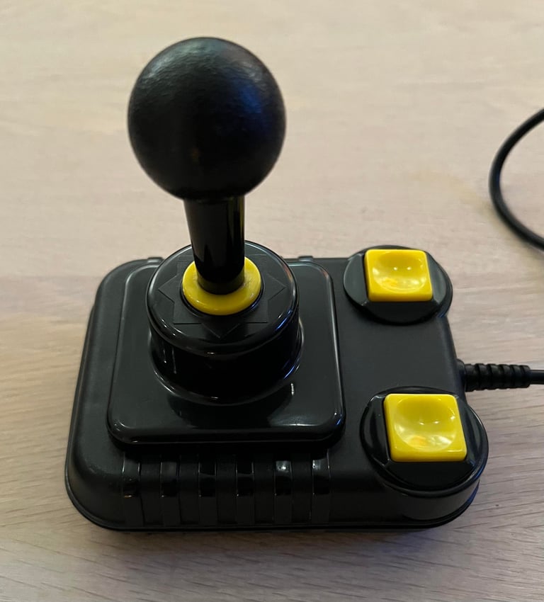
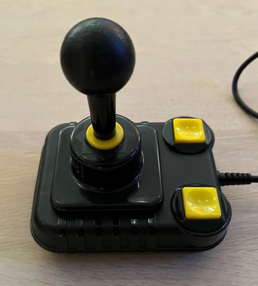
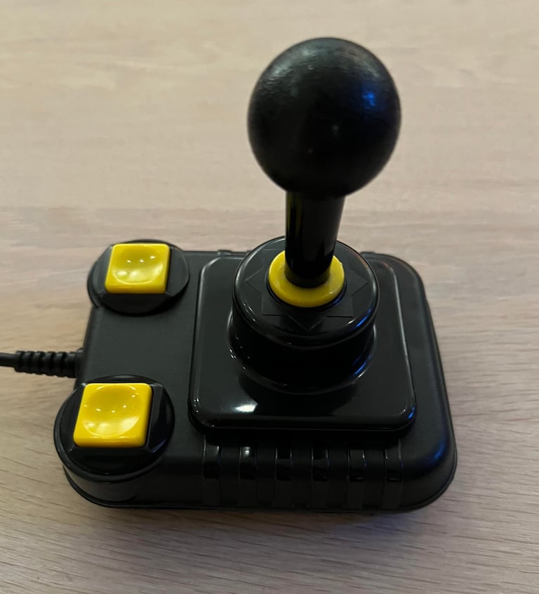
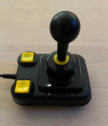
It is no secret. ZipStik is my favorite joystick for the Commodore 64 and Amiga. But this joystick has seen better days…
… it is very dirty and there are some odd marks from glue or something around the shaft area. There is grease everywhere, but the microswitches sounds ok by the clicking noise. Turning the shaft around it also feels quite ok, but it is quite squeaky. The cable is the only thing that looks quite nice already so that is something. One of the rubber feets are missing.
Nevertheless, I think that this joystick can be refurbished back to its glory!
Below are some pictures before the refurbishment.

Refurbishment plan
To refurbish this joystick the plan is to do this trough the following steps:
- Clean, and remove stains from, chassis and all parts
- Clean and check the microswitches (and repair if required)
- Check connectivity (and repair if required)
- Verify joystick operation by testing
Opens it up...
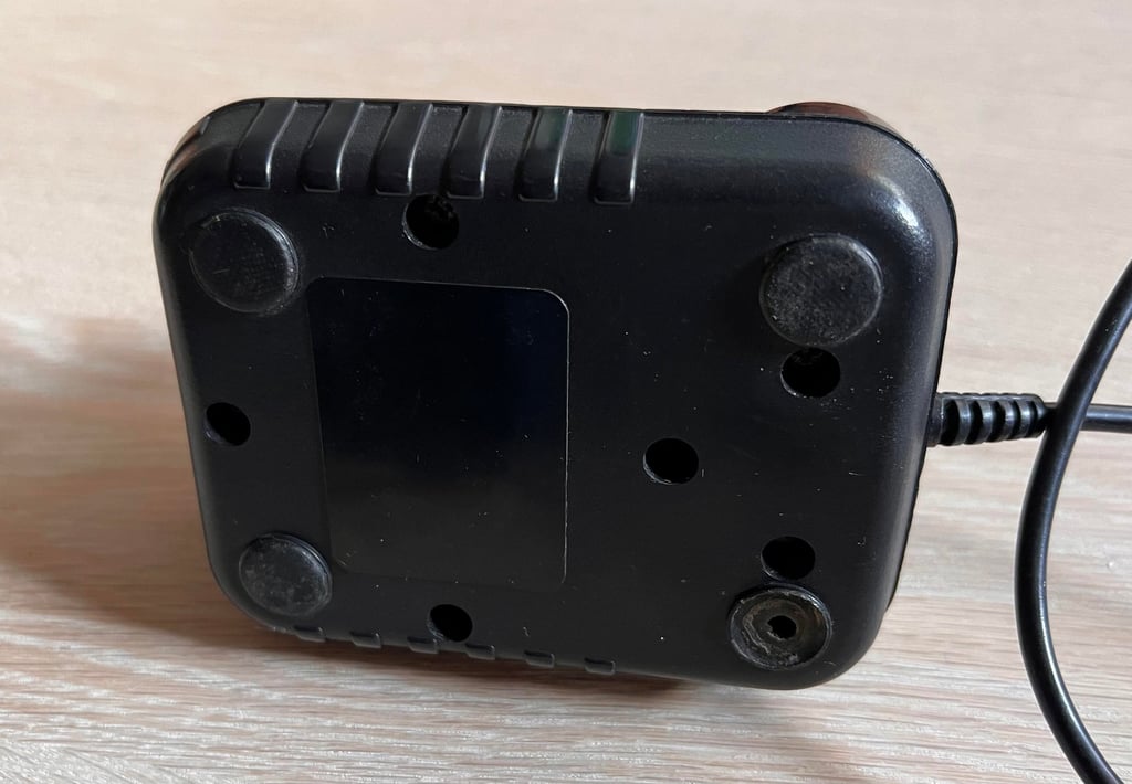
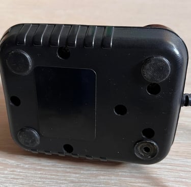
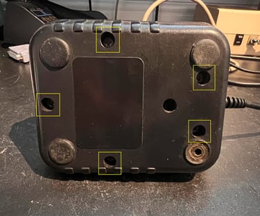
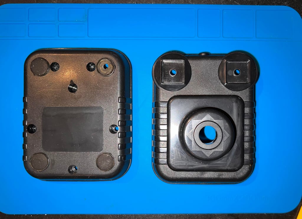
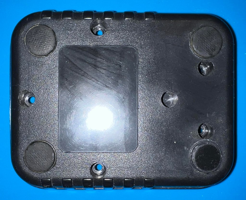
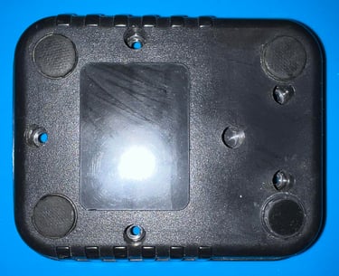
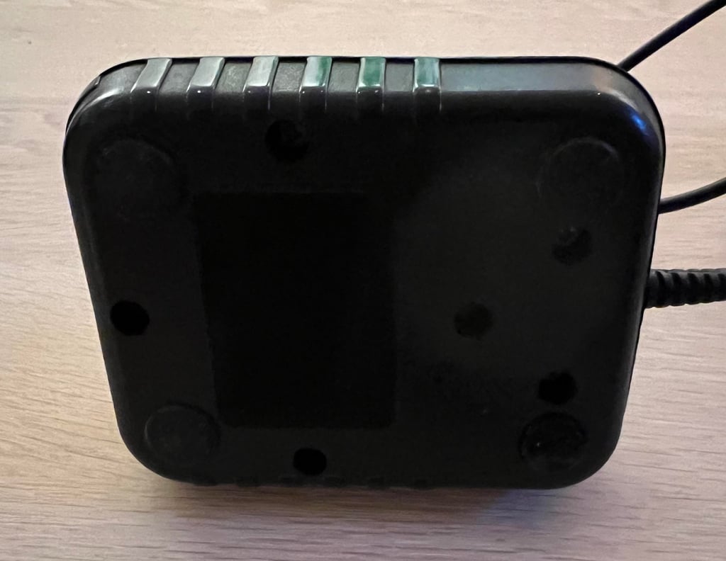
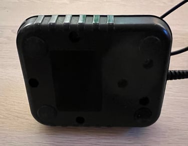
The joystick consists of a top- and bottom cover. To open the joystick the five screws are removed from the bottom. See picture below.

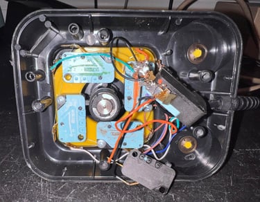
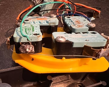
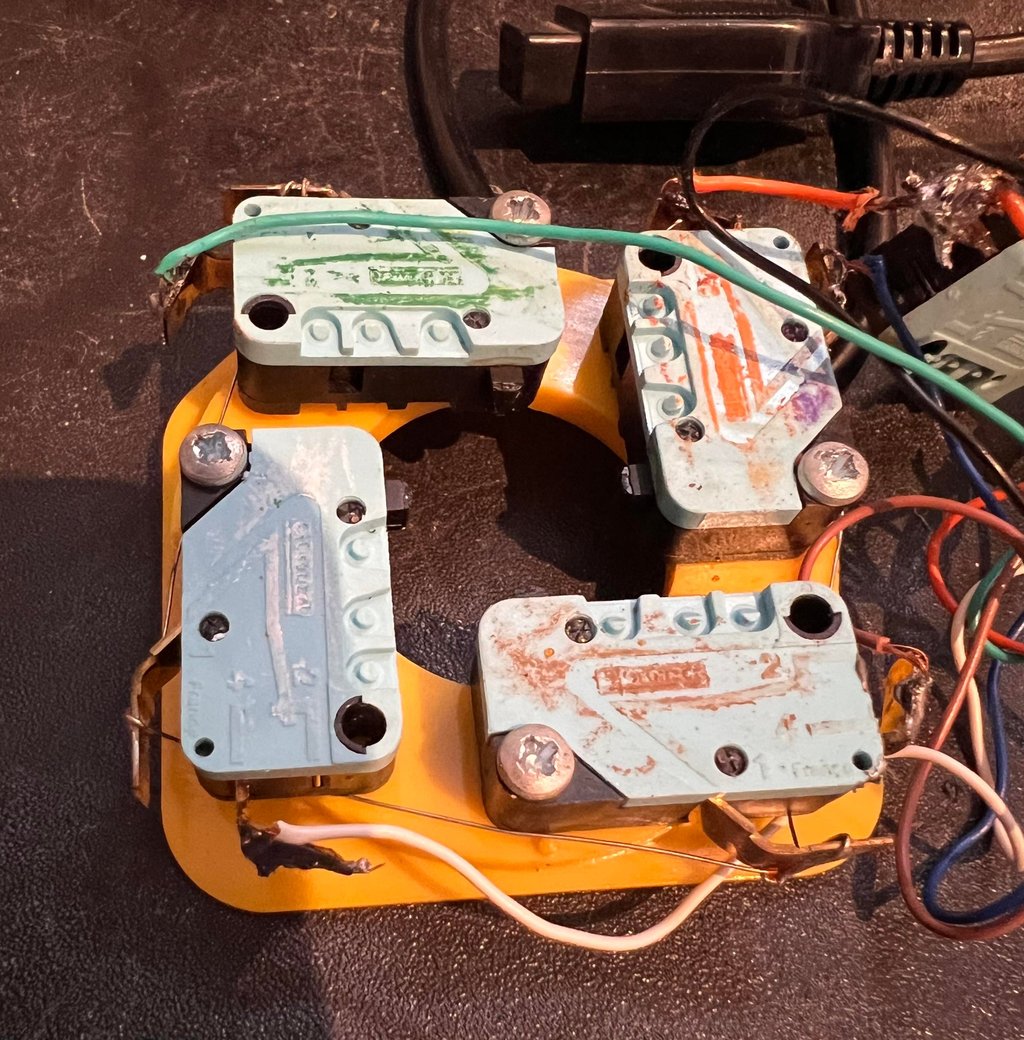
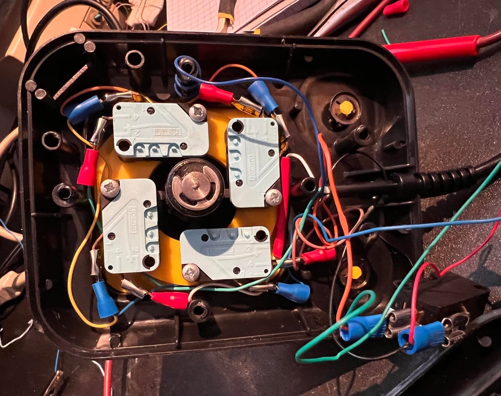
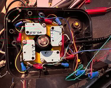
The bottom cover is removed and the inside of the joystick is revealed. Holy moly… what… is… this? Someone has obviously tried to repair this joystick before. I notice the following:
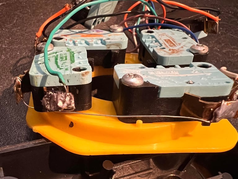
Non-isolated wire is used for common ground connection between several of the microswitches
One of the wires is partly broken
Large solder blobs connecting the wires to the micro switches
Residue of old wires (not used) stuck on several of the micro switches
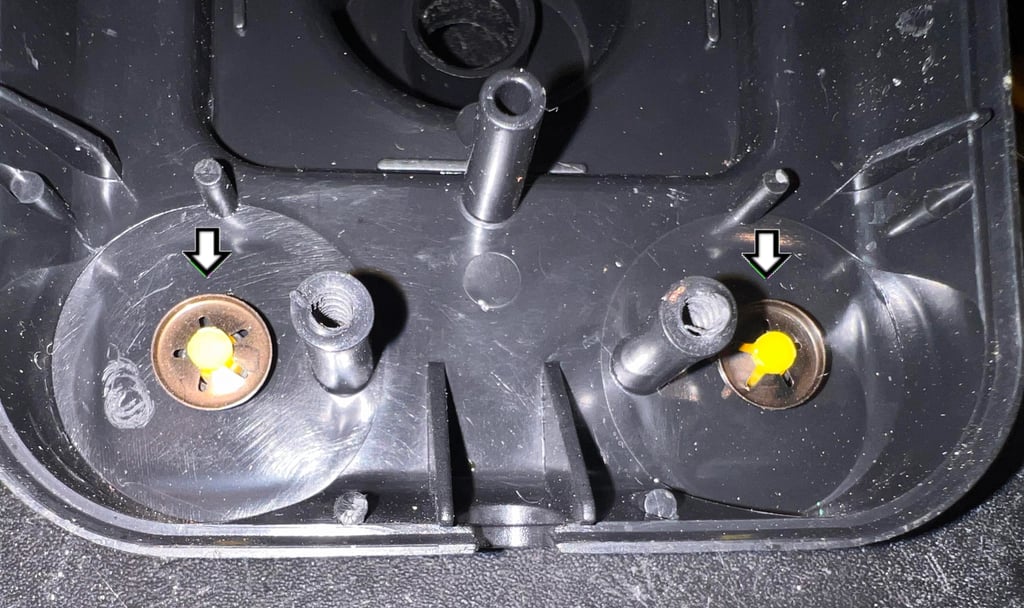
Four of the six microswitches have residue from a color pencil (?)
See pictures below

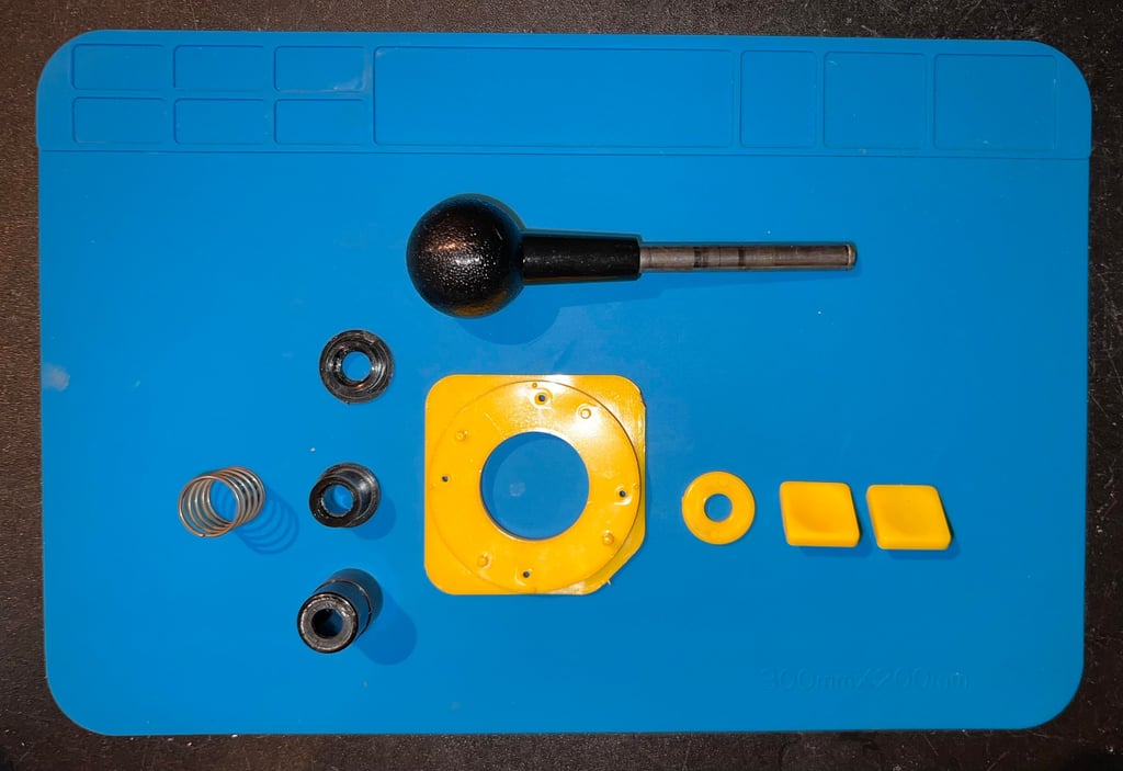
The yellow bracket holding the four micro switches are removed. Then the e-clip is removed using a flat screwdriver. When the e-clip is no longer holding the shaft in place, the remaining plastic cylindrical parts are removed. See gallery below.
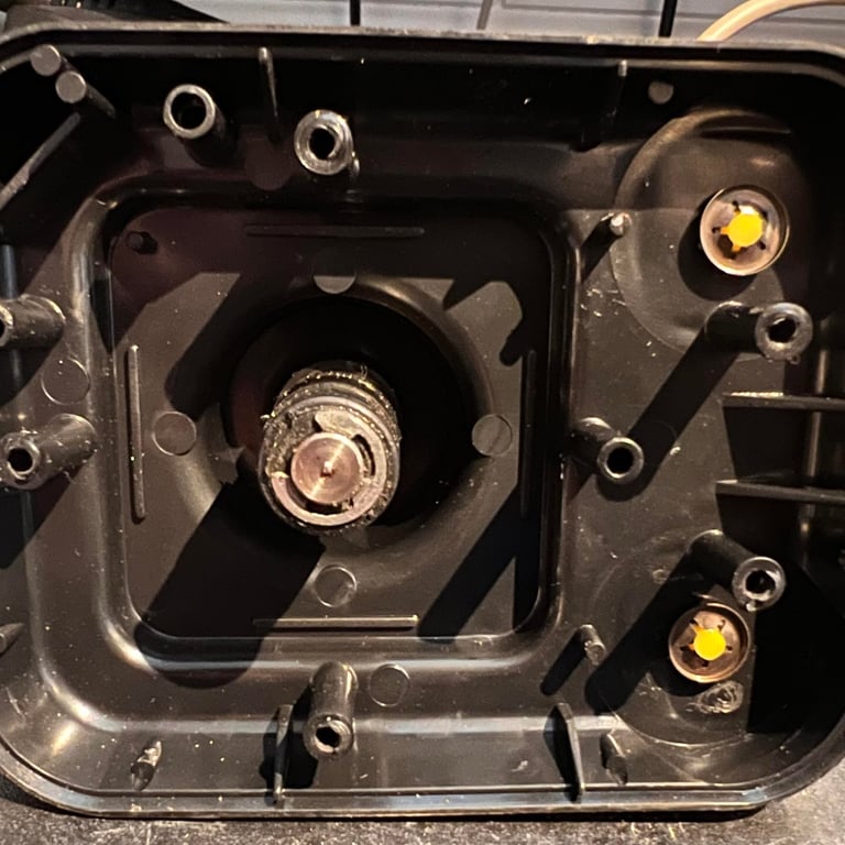
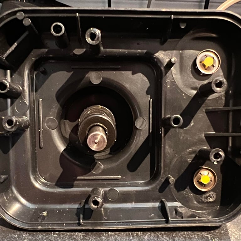
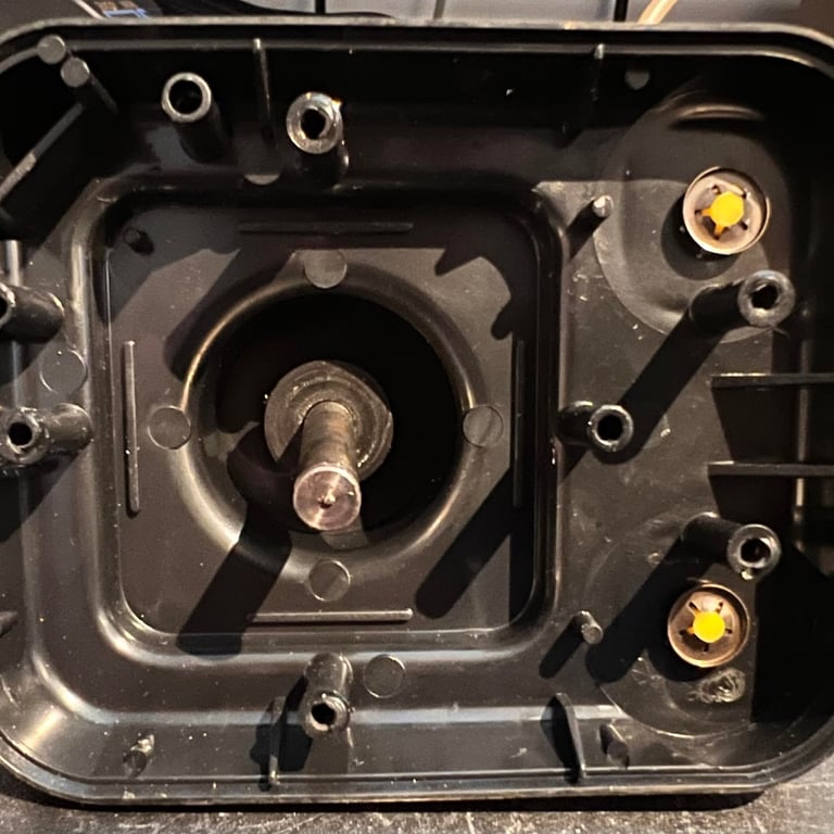
The shaft is removed from the top cover. There are two metal clips fastening the fire buttons to the top cover. These are removed using a pair of needle nose pliers. Note that it can be quite hard to remove these – so be careful not to break them.

Exterior casing and plastic parts
As seen from the pictures in the “Starting point” section the casing is VERY dirty. All parts are placed in mild soap water for about 12 hours. This removes most of the grease. To remove all the grease and dirt a combination of more soap water, isopropanol, glass cleaning spray and hard work is applied. What looked like some kind of glue (?) residue was removed with isopropanol and Q-tip.
I am very pleased with the result. As can be seen from the pictures all of the dirt is gone – and all of the weird marks are also gone.

Before re-reassembly some CRC multi grease and some sewing machine oil is applied to several of the plastic part. This is to make sure that all moving plastic parts can be used with minimal friction.
One of the rubber pads are missing on the bottom cover. A new pad is ordered from retroleum.co.uk and installed. These are not 100 % identical to the original rubber pads but they are quite close.
Interior
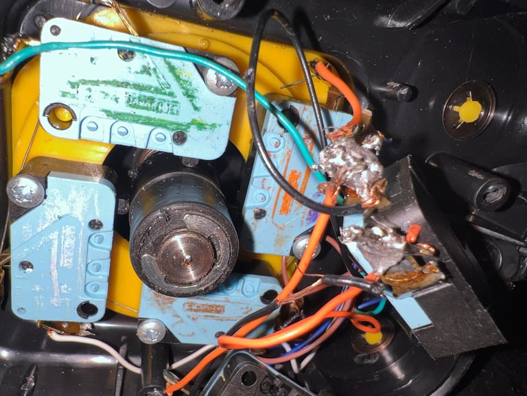
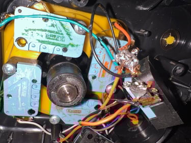
This interior is the most messy I have seen in a Zipstik so far. Big solder blobs, non-isolated bodge wires, a broken wire and crayon colored micro switched.

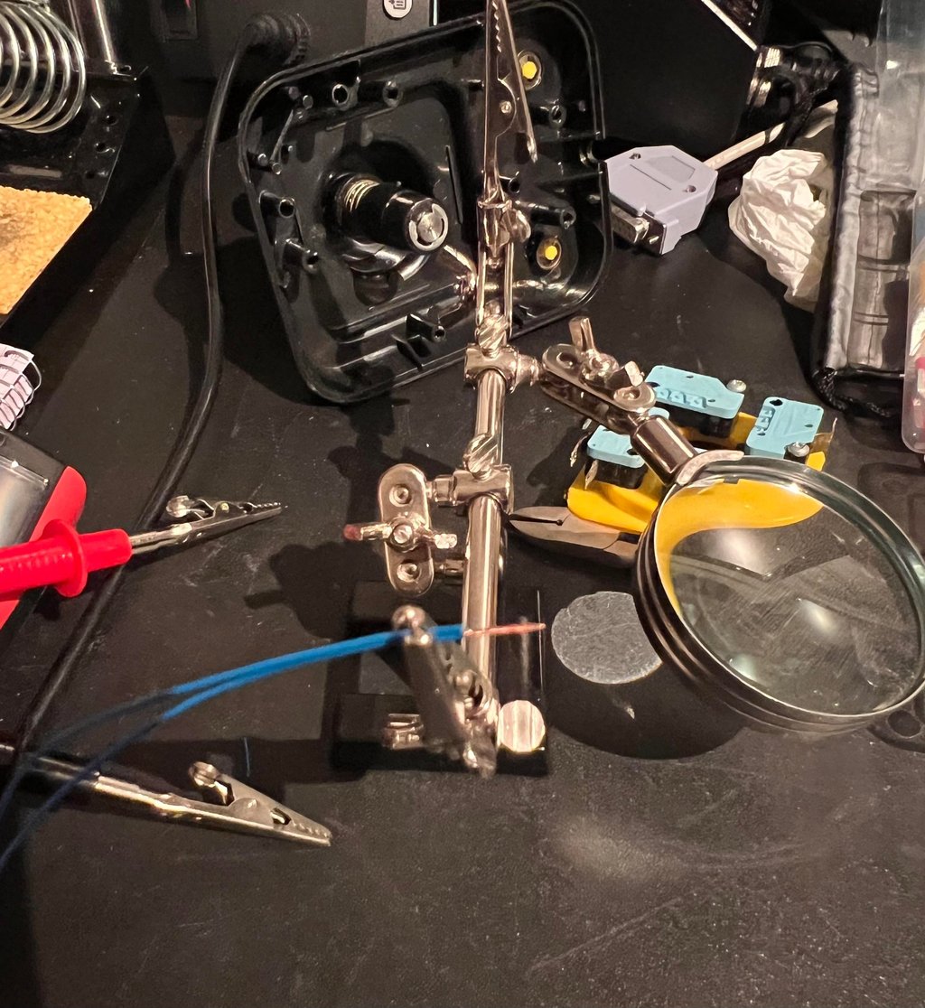
Although the wires could work I can not stand looking at this. So all the wires are desoldered from all the switches. And the metal connectors are cleaned with a desoldering gun and solder wick.
Refurbishing the micro switches
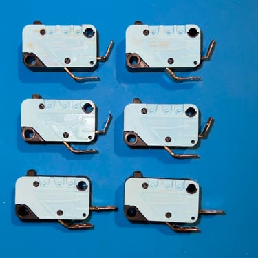
Then all the micro switches are placed in a jar filled with isopropanol. This will clean both the inside and outside of the switches.
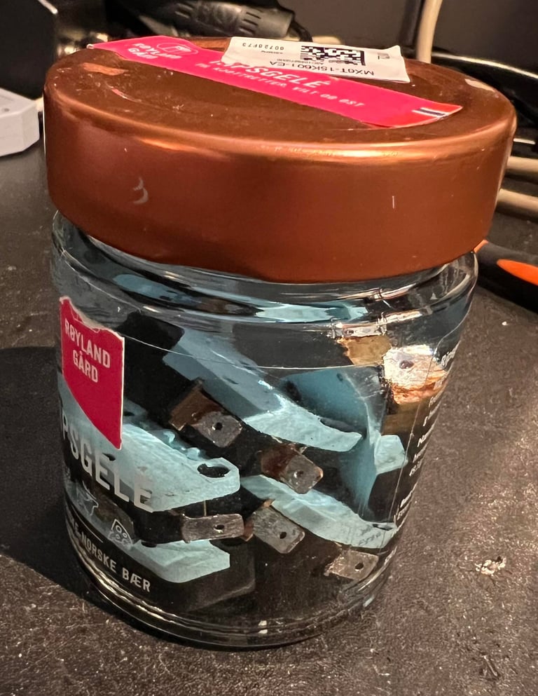

After a few hours in the isopropanol bath and spa the micro switches looks “as new”. We can now see that these are quality switches from Crouzet.
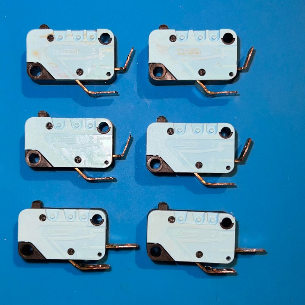
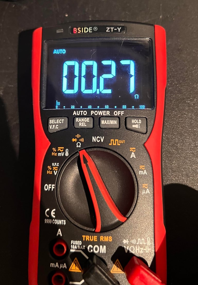
All the micro switches are tested after they are dried up. The resistance is about 0.30 ohm in closed postion which is perfectly fine.

Repairing the broken wire
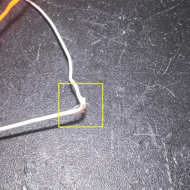
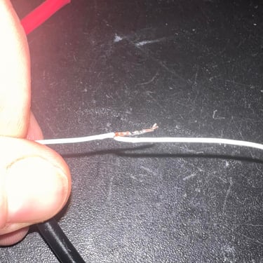
Joystick wires are very thin. So when a wire is broken, or partly broken, the risk is great that it will not work properly. Therefore it is essential that the broken wire is repaired. This is done by cutting the broken wire in two parts; just where the broken part is visual.
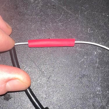
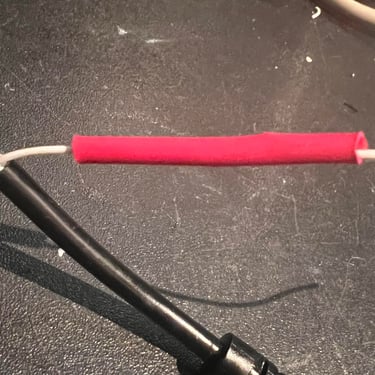
Then the isolation is removed from the top of the wires, entangled and then soldered. Finally some heat-tube shrinking is added to the wire. See picture gallery below.
Reconnecting the wires
Instead of soldering the thin wires to the micro switches I go for some cable plugs. Each end of the wire is twisted, soldered and then clamped to the plug. Finally the plugs are “squeezed” to reduce the risk that the are displaced during action. Below are some pictures of the mounting process and the interior after all plugs are in place.
The six wires (UP/DOWN/RIGHT/LEFT/FIRE/GND) are connected according to the pinout shown below. Note that in this schematics the pinout is as seen from the computer side – if you are to see it from the cable side you need to mirror the pinout.


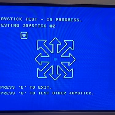
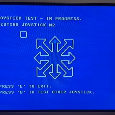
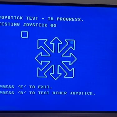
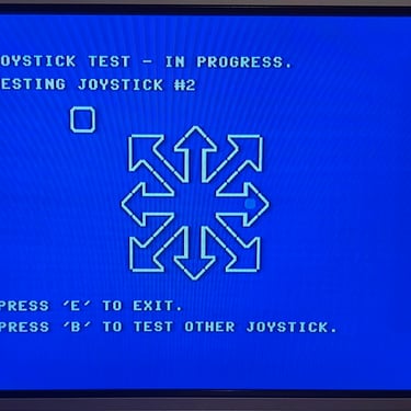
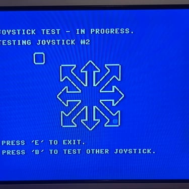
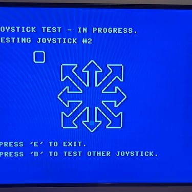
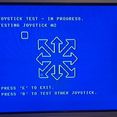
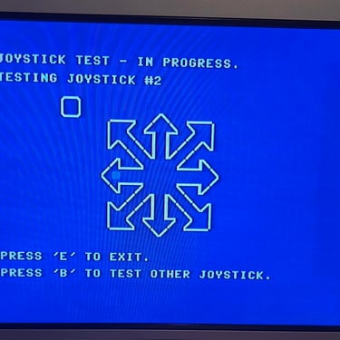
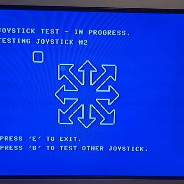
Testing
To verify that the joystick work as it should I check it with the 64 Doctor software. Result is that all directions and fire buttons works fine works as expected. All tests pass.
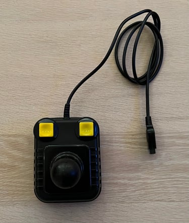
Final result
"A picture worth a thousand words"
Below is a collection of the final result from the refurbishment of this Zipstik joystick. Hope you like it! Click to enlarge!


Banner picture credits: unknown