

Zipstik
Starting point
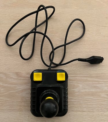
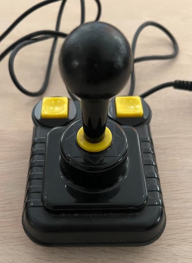
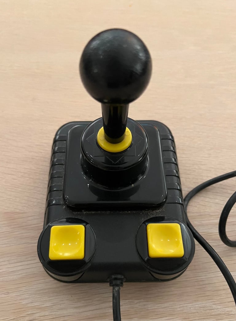
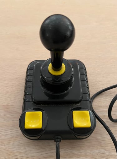
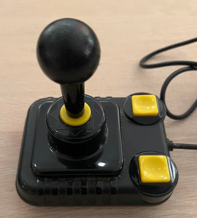
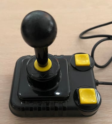
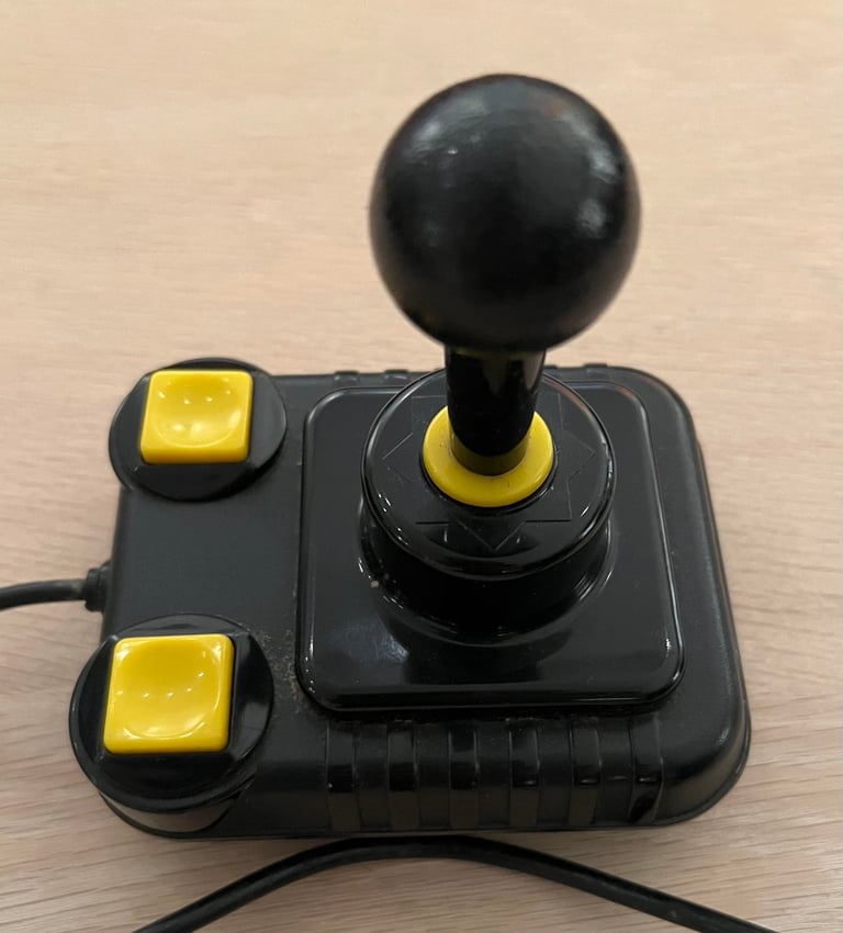
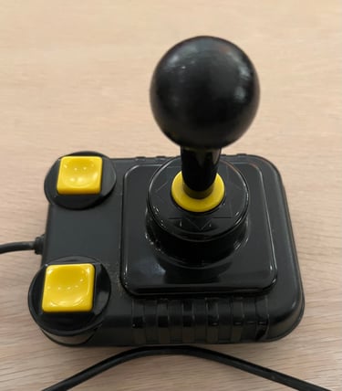
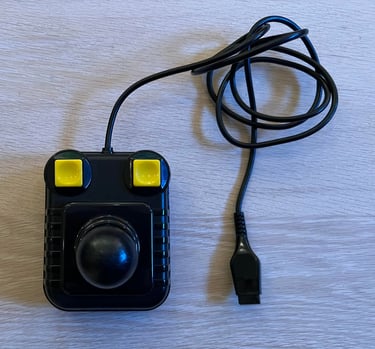
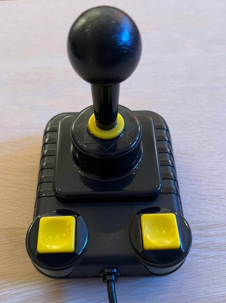
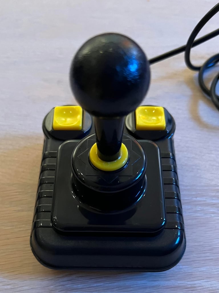
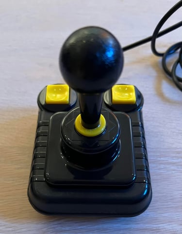
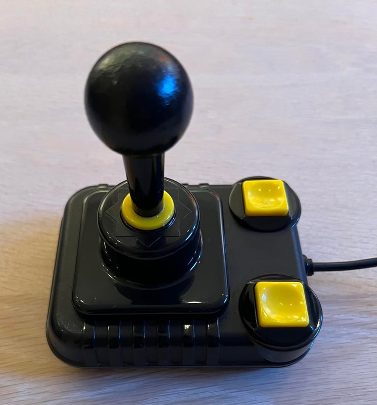
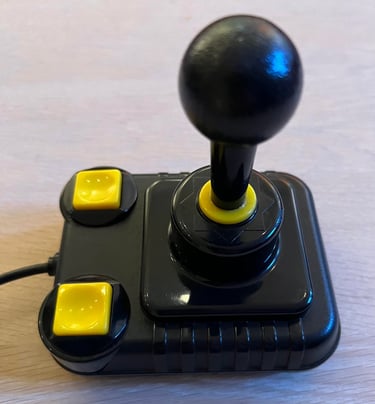
"Don´t judge a book by its cover" - from the outside this joystick looks quite ok, but when trying to push the FIRE buttons or move in some directions there is obviously something going on inside. The joystick makes squeaking sounds when pushing the shaft around the directions, and when the FIRE buttons a pushed you can barely feel or hear the clicking microswitches.
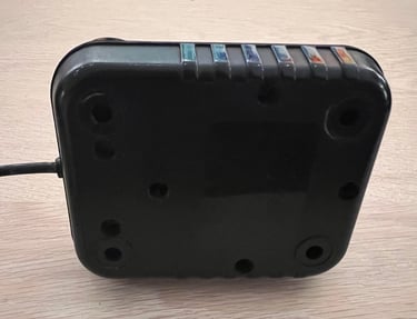
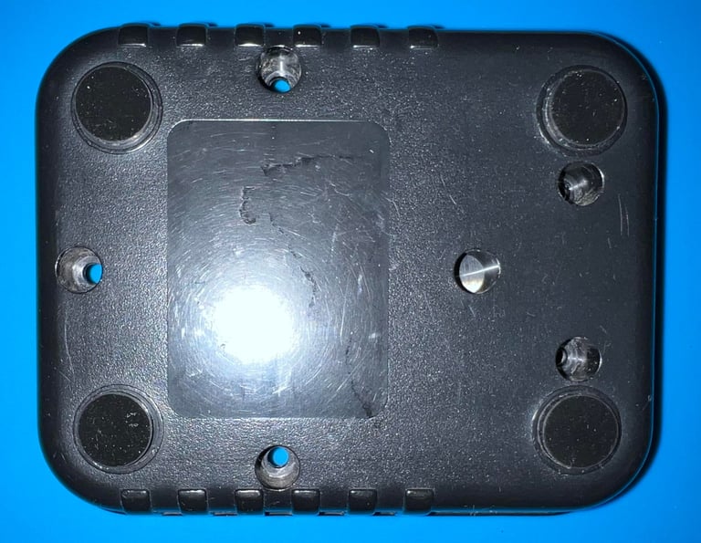
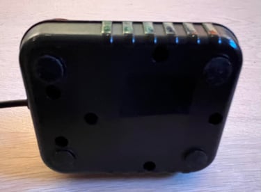
All the four rubber feets (or suction cups) are missing. Even though this is the first time I have seen that all the four rubber feets are missing I don´t think this is from factory. My hypothesis is that someone removed these intentionally some time back in the days.
But the rest of the exterior looks fine. It appears to be undamaged and well taken care of. Yes, it is somewhat dirty but that is to be expected after 30-40 years. Below are some pictures before refurbishment.


Refurbishment plan
To refurbish this joystick the plan is to do this trough the following steps:
- Clean, and remove stains from, chassis and all parts (and repair if required)
- Lubricate moving parts
- Clean and check the microswitches (and repair if required)
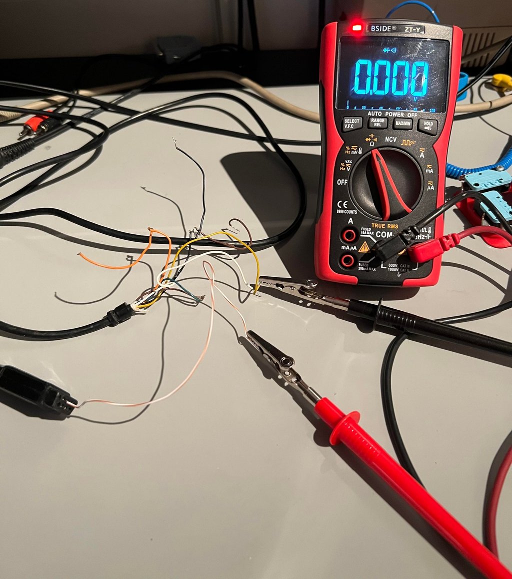
- Check connectivity (and repair if required)
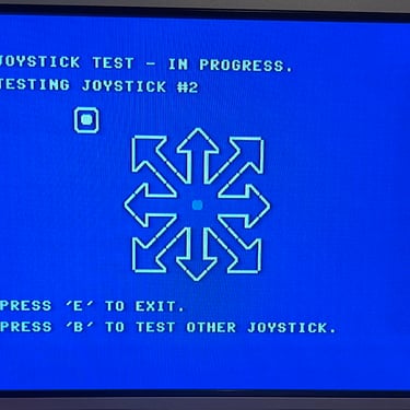
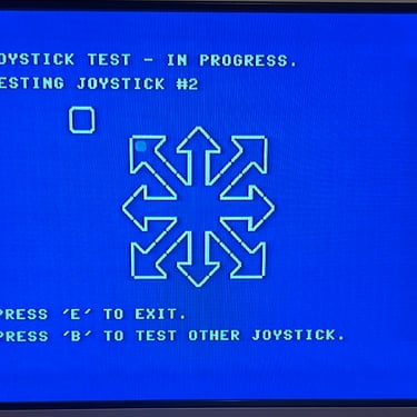
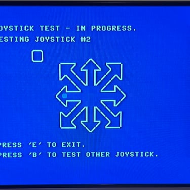
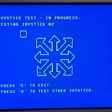
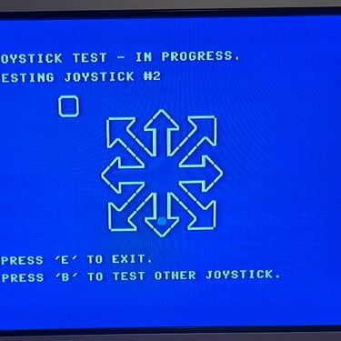
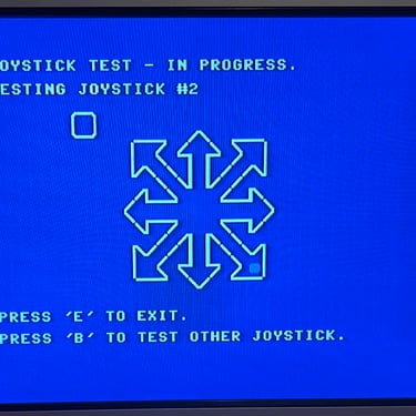
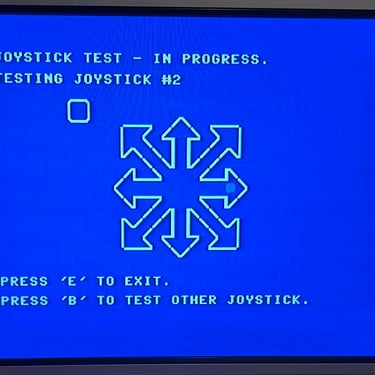
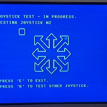
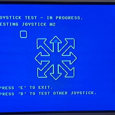
- Verify joystick operation by testing
Disassembly
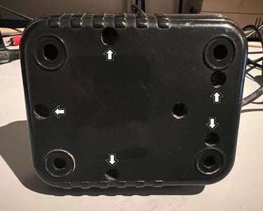
To open the Zipstik joystick the five large screws are removed from the bottom cover. The plastic is brittle so the screws are removed carefully.

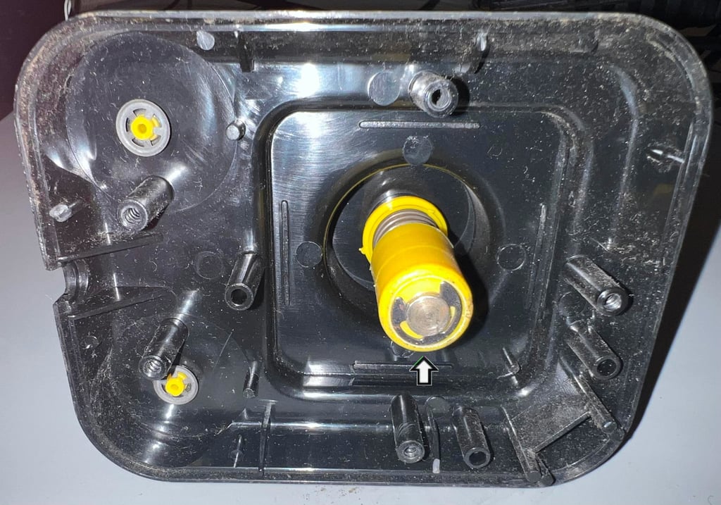
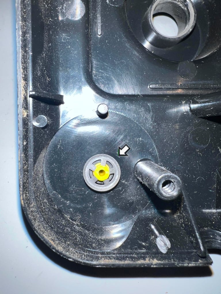
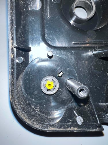
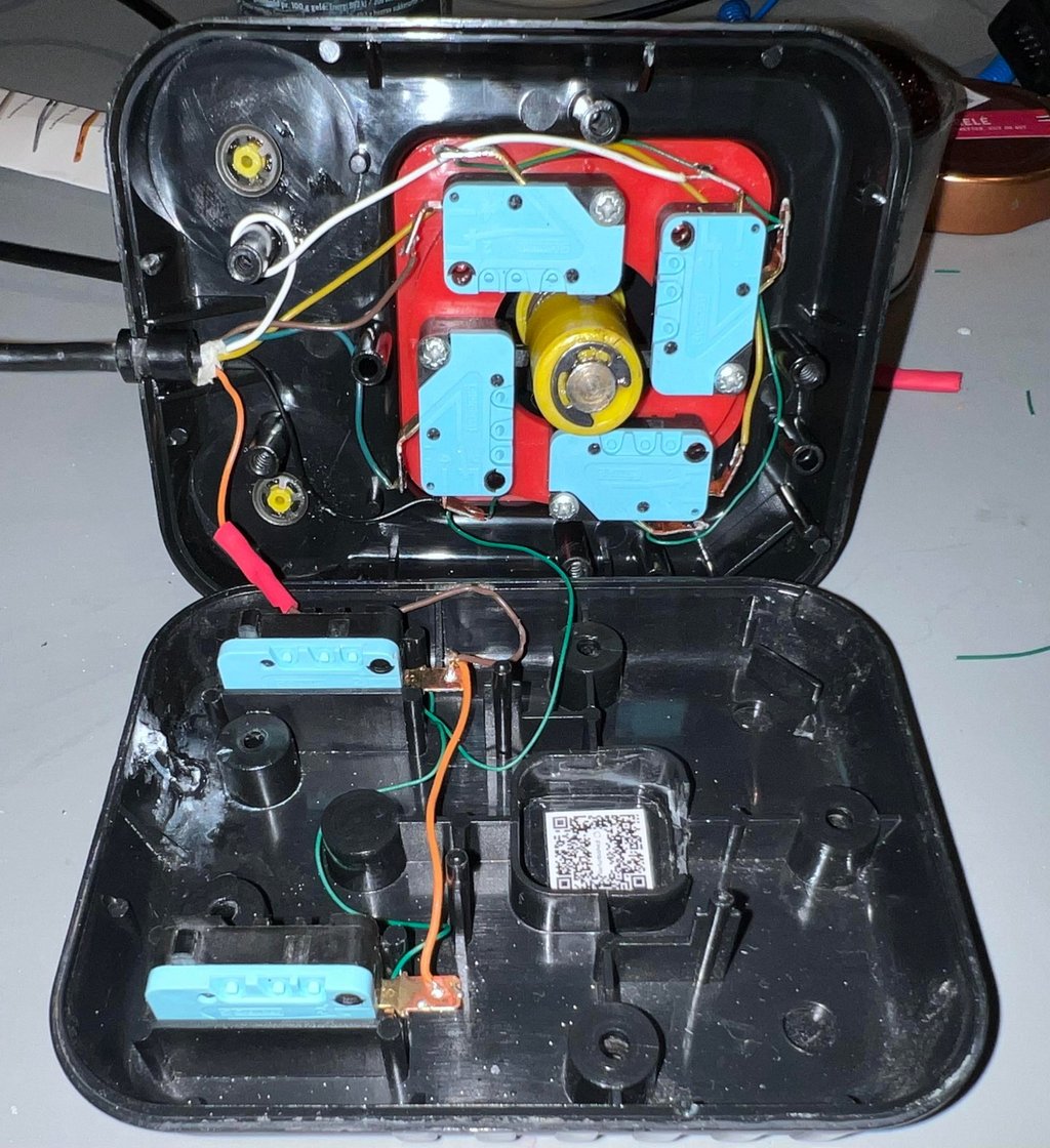
The inside of the joystick doesn´t look bad at all. So I am positive that cleaning and lubrication can make wonders for this joystick. Although, I notice that there is a small broken / bent plastic stem - but I am struggling to see the purpose of this? It is too long to fit between the top- and bottom cover (?) so gluing it back would not work. As long as I don´t find any meaningful purpose for this I will probably leave it like it is. It should not affect performance in any way. See the arrow in the picture below for the broken stem.

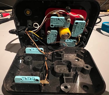
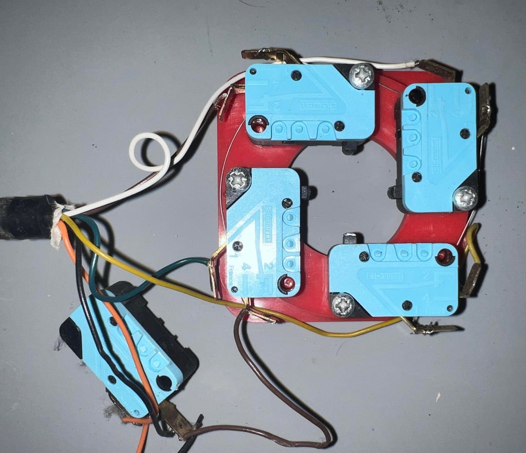
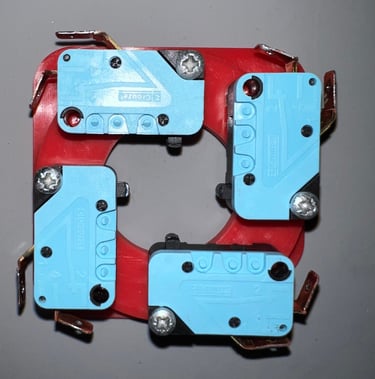
It is not easy to see it in the pictures below, but the meal contacts on the microswitches are heavily oxidized. That in itself is not a problem in regards of functionality, but I plan to remove all the microswitches as part of cleaning. So the metal contacts needs to be de-oxidized before desoldering. In addition there is a thin non-insulated ground wire connecting four out of the six microswitches. This is ok, function wise, but I think this looks "simple". I want to replace this with a proper insulated wire. Finally, the strain relief looks a bit shortened. But I am not sure if this is really the case. The strain relief appears to work fine as I can not move the cable in any way.
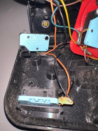
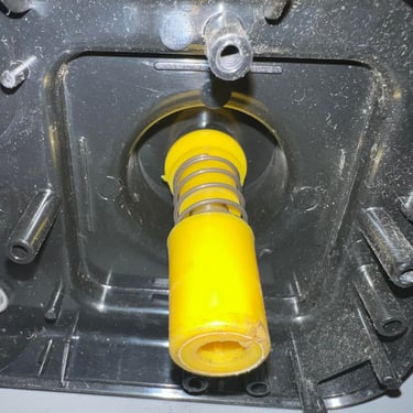
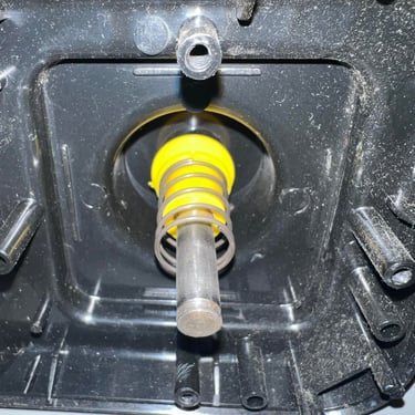
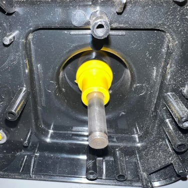
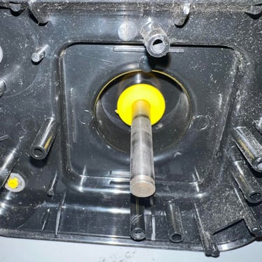
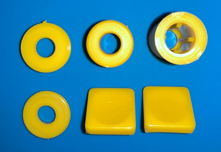
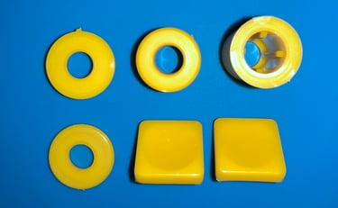
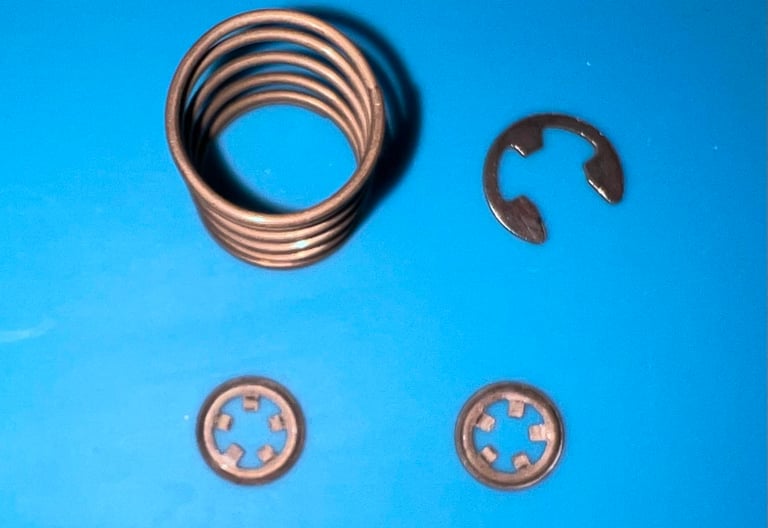
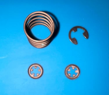
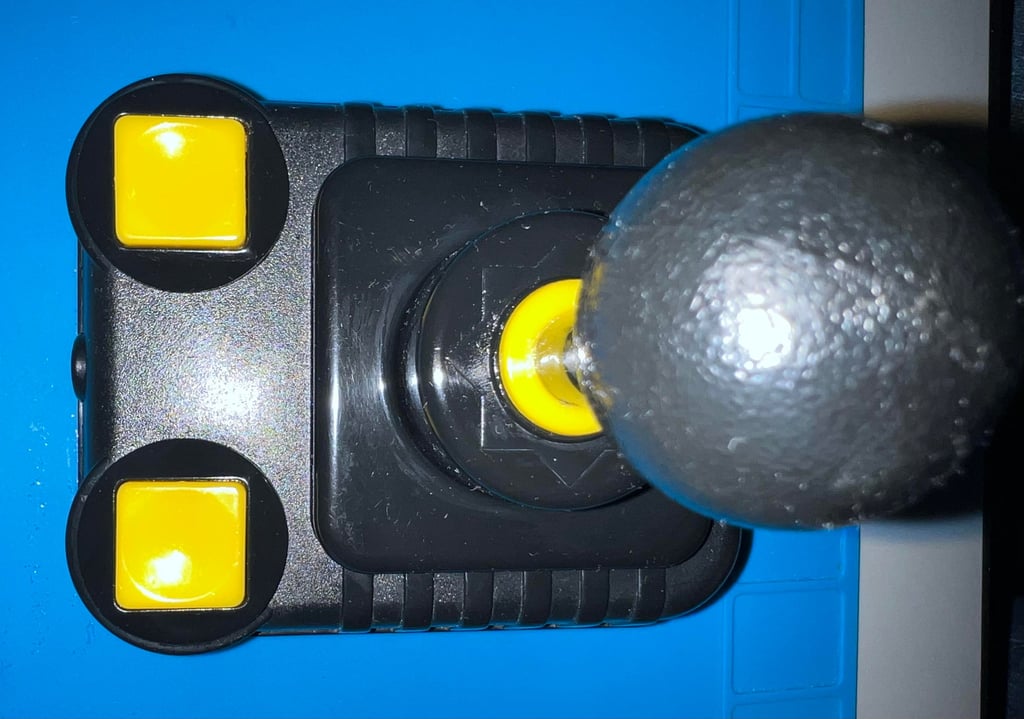
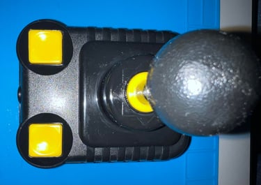
To disassemble the shaft the E-clip is removed by using a thin flat screwdriver. See arrow in picture below.

With the E-clip out of the way the remaining plastic parts, and the metal spring, are removed. Notice the order of these plastic parts. In the gallery below pictures of this disassembly are shown.
There is a small metal clip beneath each of the two fire buttons. With a pair of needle nose pliers these are carefully removed. It is important not to rush this small operation - take care not do damage neither the fire button or the metal clip.
Exterior casing and plastic parts
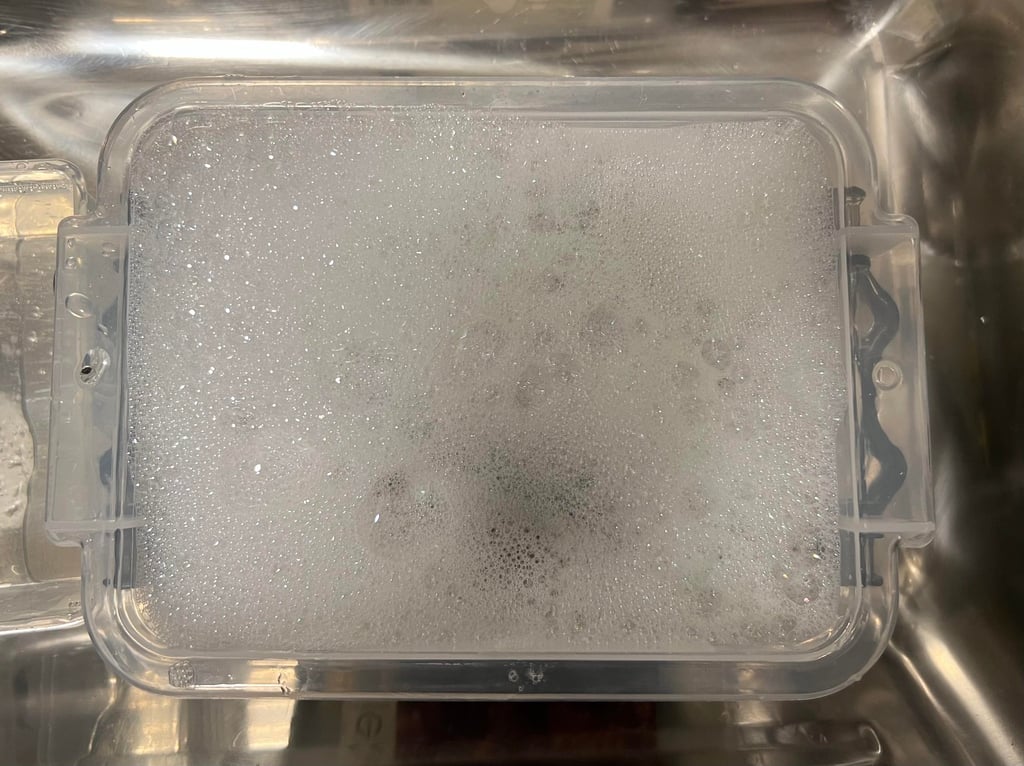
First things first - all the plastic and metal parts must be thoroughly washed first. The parts are placed in a box filled with mild soap water for about 48 hours. Note that I don´t use warm water. Instead I start with luke warm water and let this cool to room temperature. Indeed, warm water would speed up the process, but I do not want to risk deforming the plastic.

The result of the washing is very good. All of the dirt is gone. Some stains are removed with isopropanol on a Q-tip.
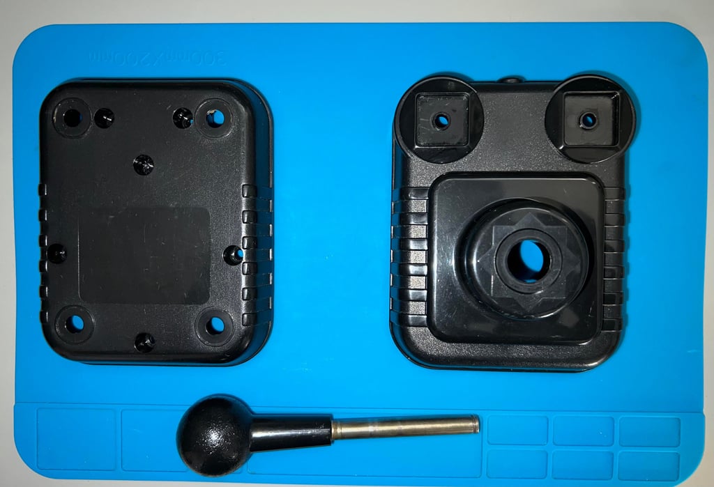

After cleaning the large plastic parts, the shaft and the large spring, are lubricated with some multi purpose grease. The underside of the two fire buttons are lubricated with a combination of a small amount of grease and then some silicone spray. All parts are then re-assembled. I can notice a big difference before and after refurbishment. All squeaking noises are gone, and the directional motions feels much better since all the friction is now gone. Below is a picture of the top cover with the shaft and plastic parts assembled.
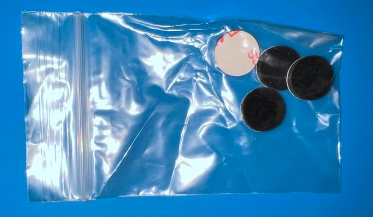
Since all the rubber feets are missing (?) a new set of replacements are ordered from retroleum.co.uk. The new Zipstik rubber feets are installed on the bottom cover - it looks very good!


Electronics and microswitches
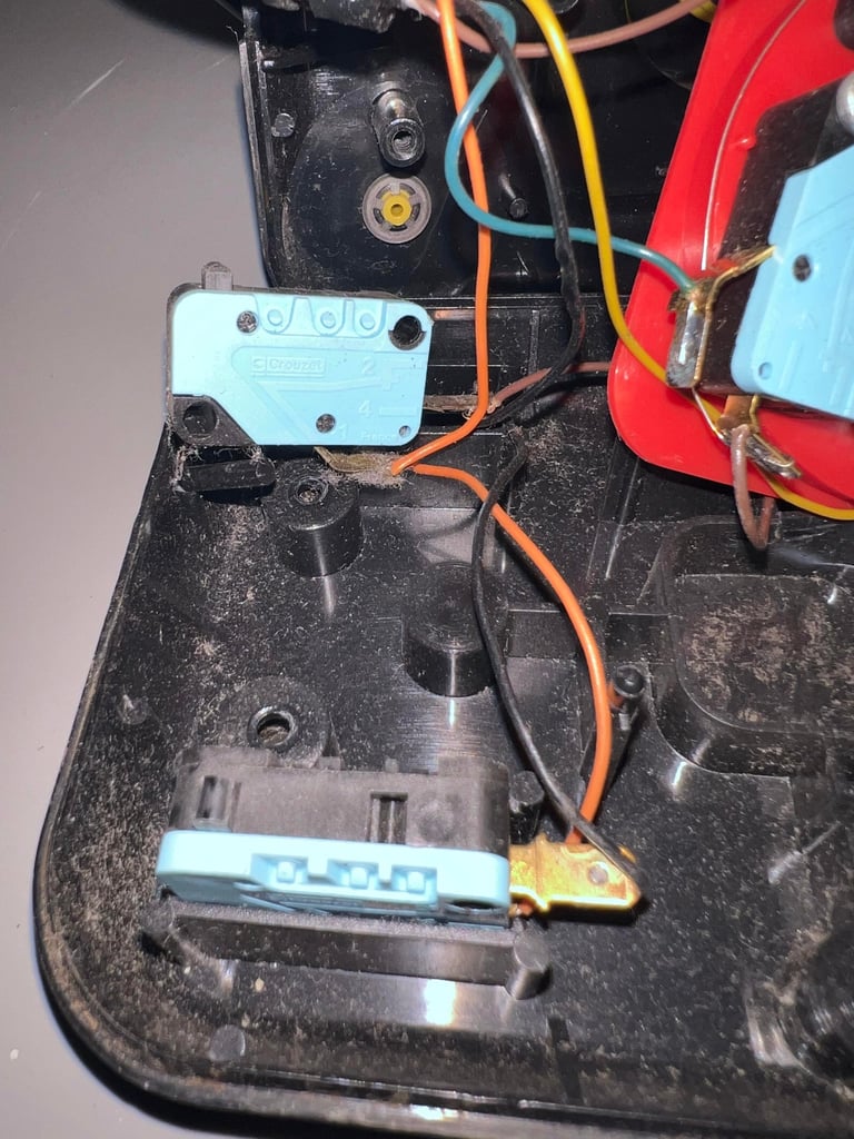
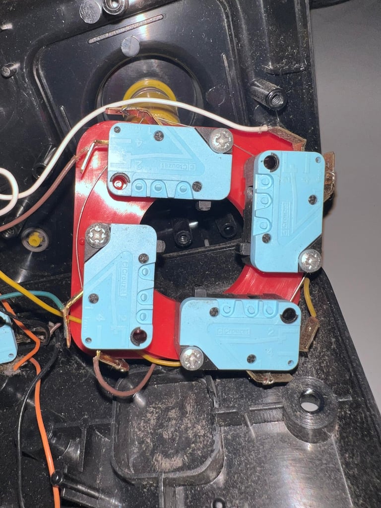
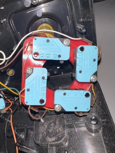
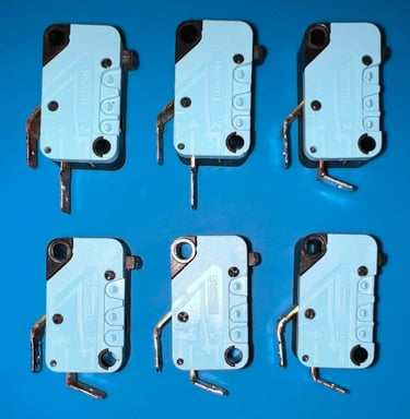
These are high quality microswitches from Crouzet. As previously mentioned the metal connectors where the wires are soldered are heavily oxidized. And since the plan is to clean the microswitches the wires must be desoldered from the connectors. With plenty of flux and the soldering iron set to about 390 degrees Celcius the desoldering works fine. Below is a picture of the microswitches before desoldering. Note that the picture doesn´t give justice - the metal connectors are way more oxidized than the picture shows.

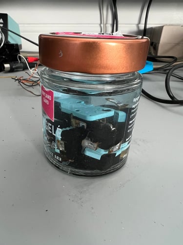
The microswitches seems to be in quite good condition. But they are old, and they are probably exposed to some dust and grease inside, so to clean them carefully thay are placed in a jar of isopropanol for about 24 hours.


Banner picture credits: unknown