
Zipstik
Starting point
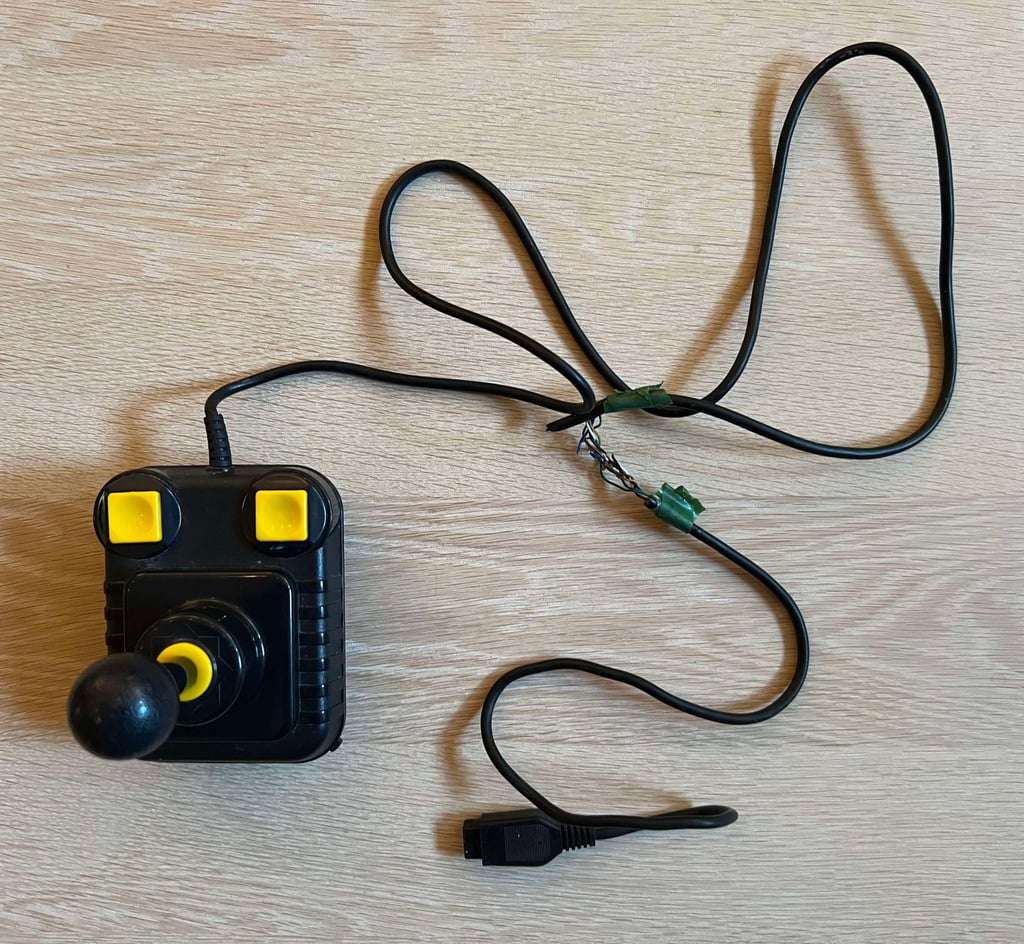
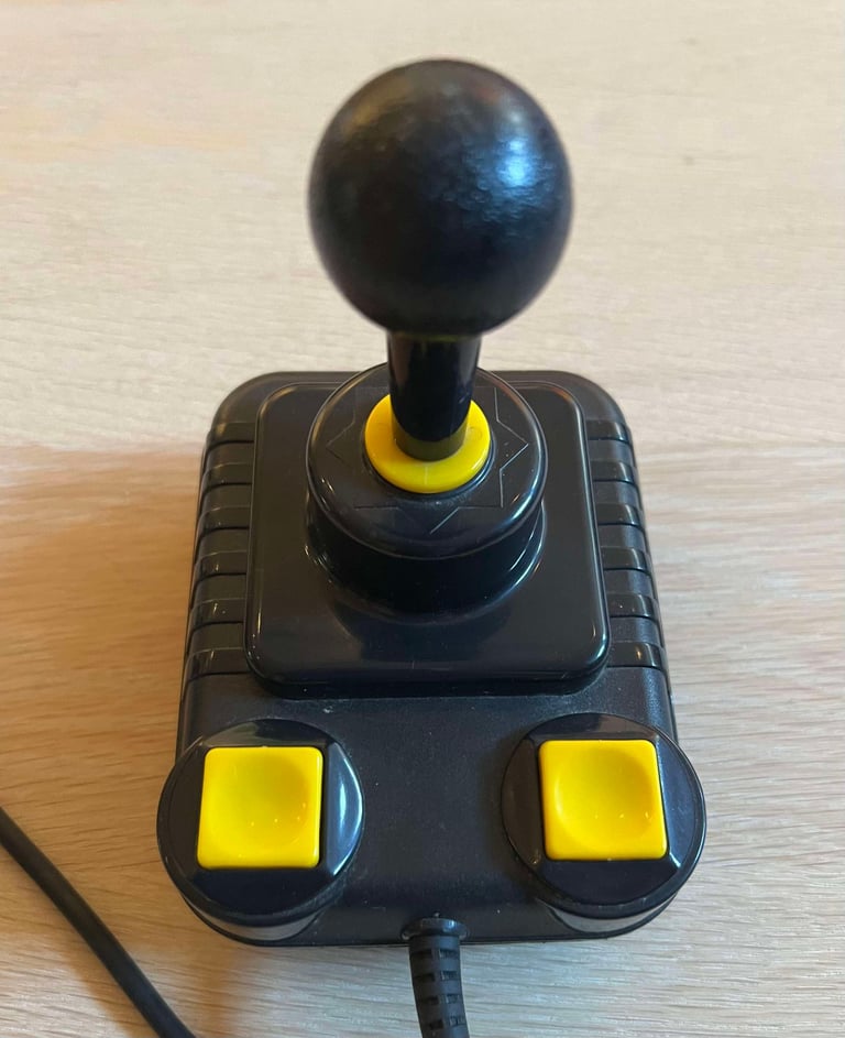
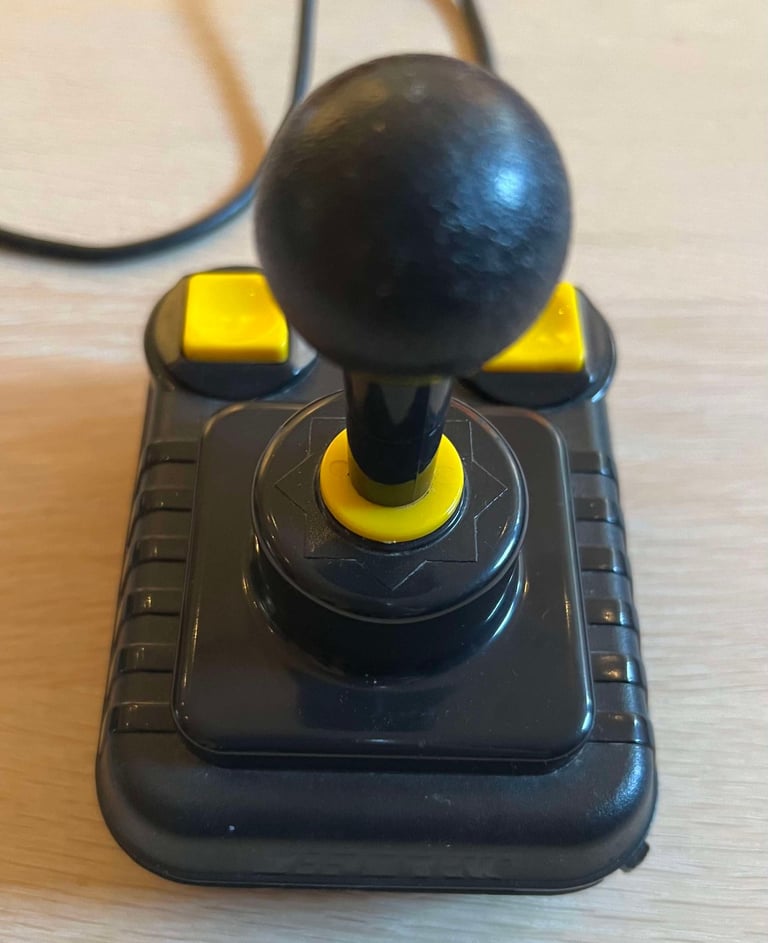
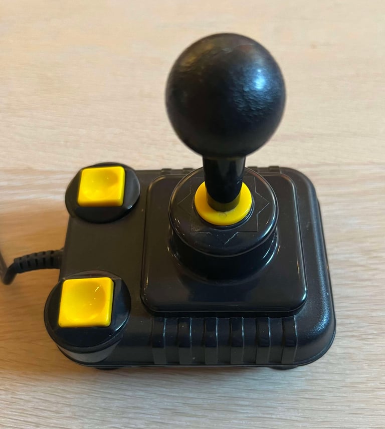
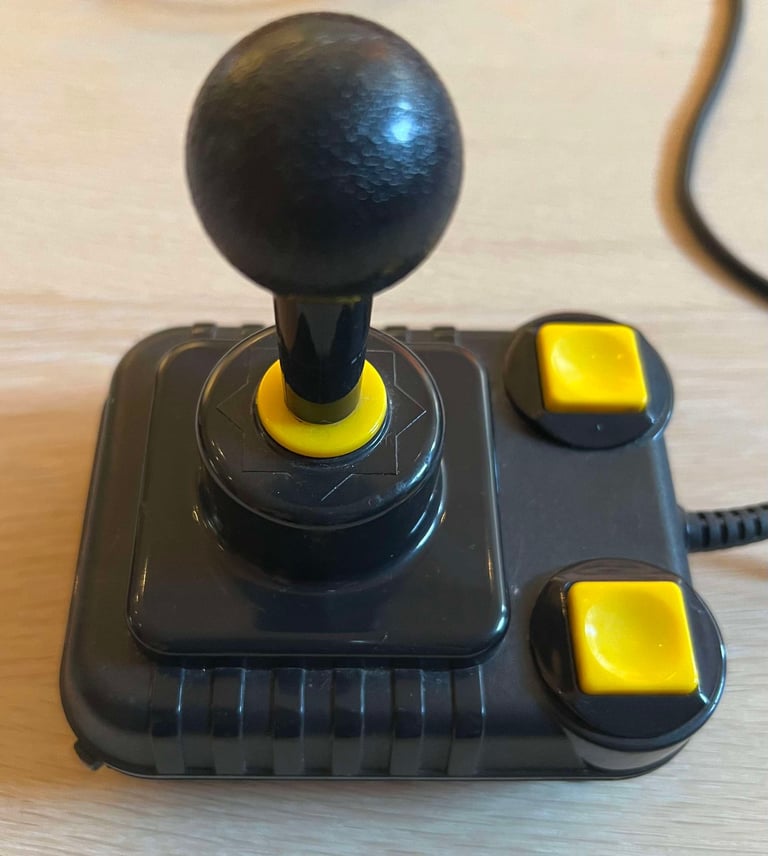
Oh my... this Zipstik has seen better days... On the bright side the plastic casing appears to be without any significant damage, only with quite some dust and grease. But there are some things which are way worse:
The cable is torn and wrecked.
The joystick is equipped with an autofire, but the switch to enable this is completely stuck.
The joystick shaft is not really stuck, but it can not really move properly in any direction. And only occasionally the "clicking" sound from the microswitches can be heard.
The top cover is not mounted properly to the bottom cover - it is severely misaligned.
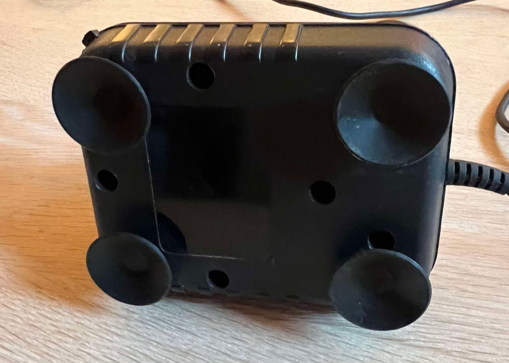
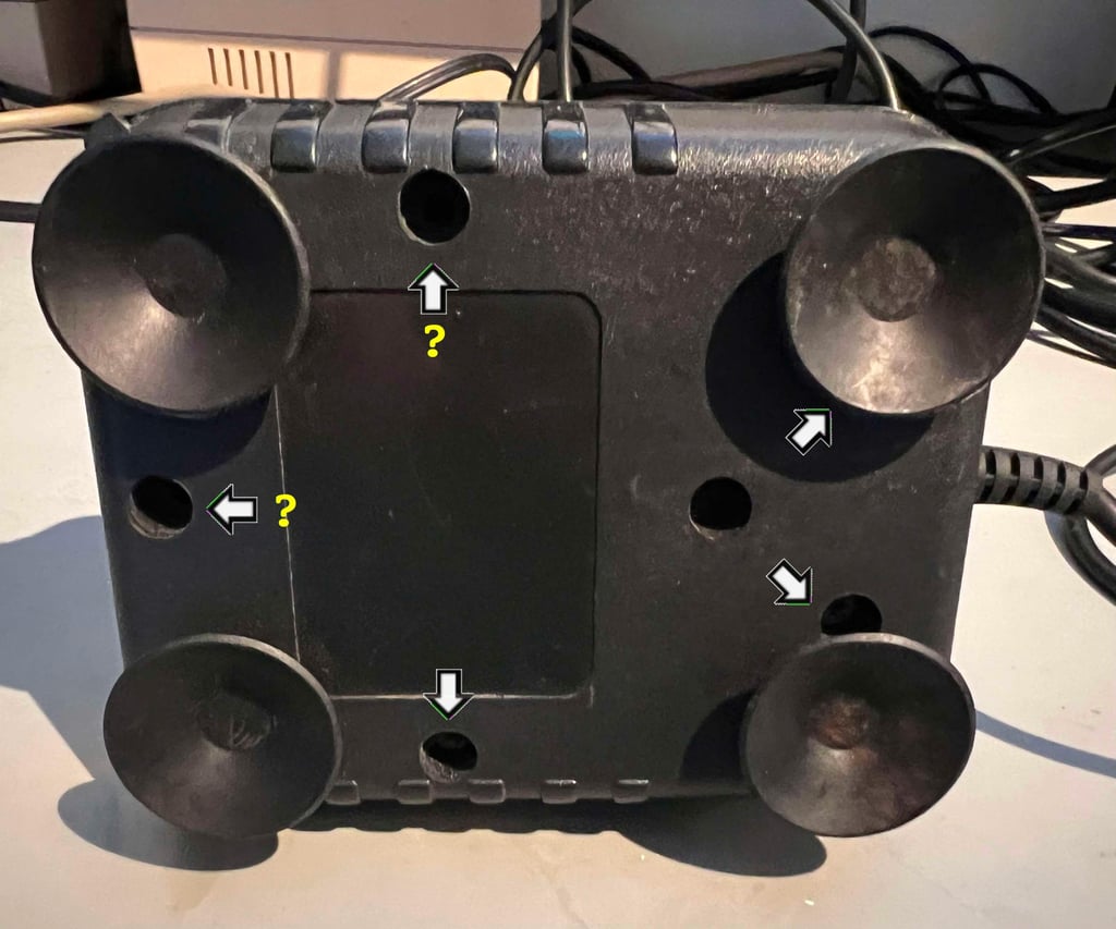
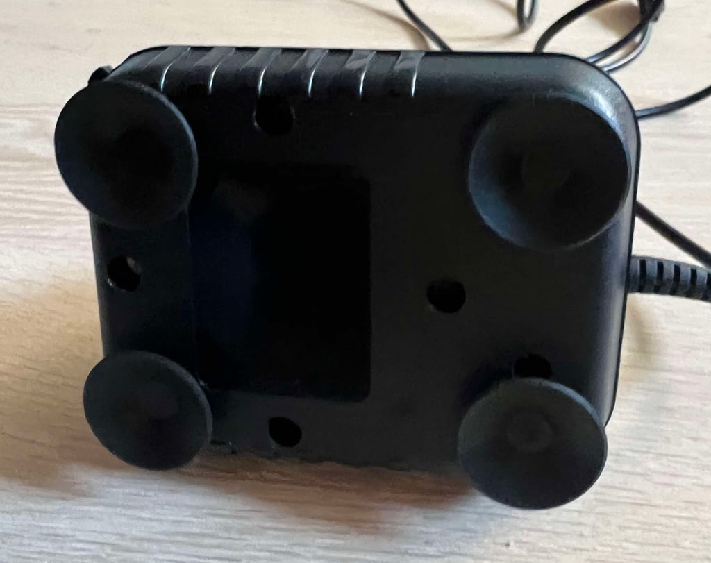
The bottom cover is mounted with only three screws. Two are missing.
Also, on the bright side the fire buttons seems to be working (or at least there is a nice clicking sound) and the four rubber feet are intact. Nice!
Below are some pictures before the refurbishment.






Refurbishment plan
To refurbish this joystick the plan is to do this trough the following steps:
- Clean, and remove stains from, chassis and all parts (and repair if required)
- Lubricate moving parts
- Clean and check the microswitches (and repair if required)
- Check connectivity (and repair if required)
- Verify joystick operation by testing
Disassembly
First the screws at the bottom are removed. There should be five of them, but two are missing.

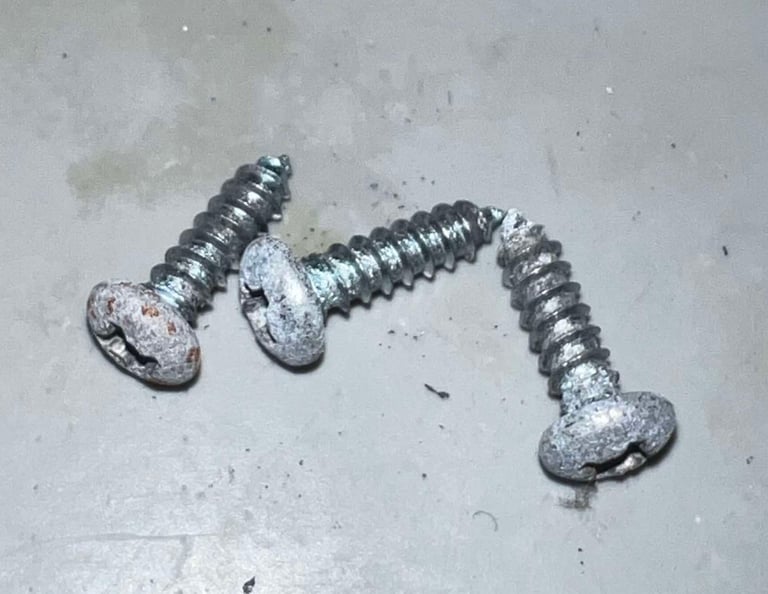
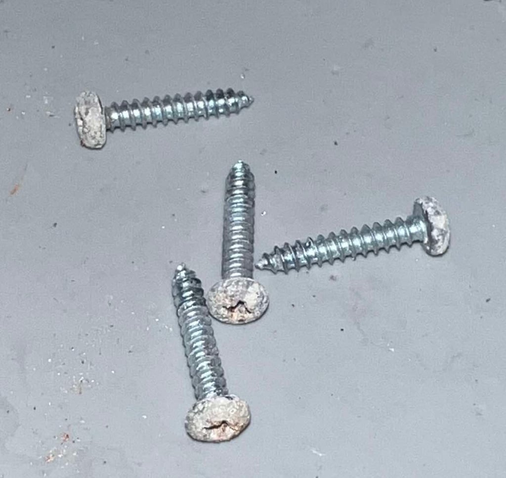
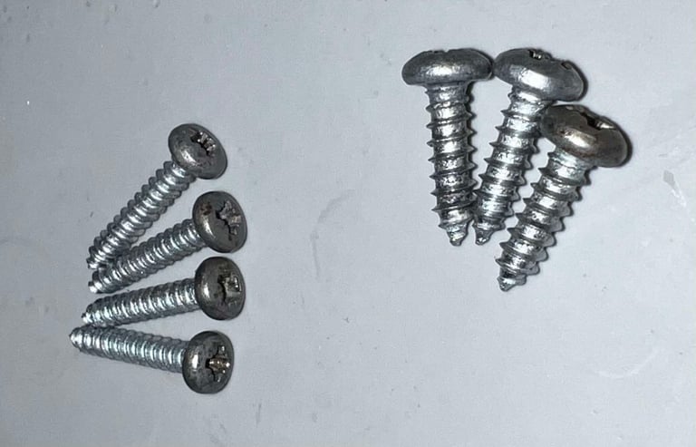
The screw heads are quite oxidized, but they appear to be in ok general condition (dimensions of the screws are 3.5 mm x 13 mm). Hopefully these can be cleaned and restored.

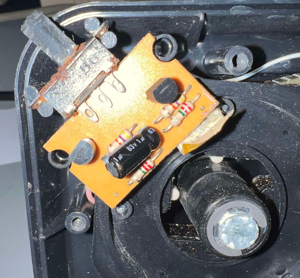
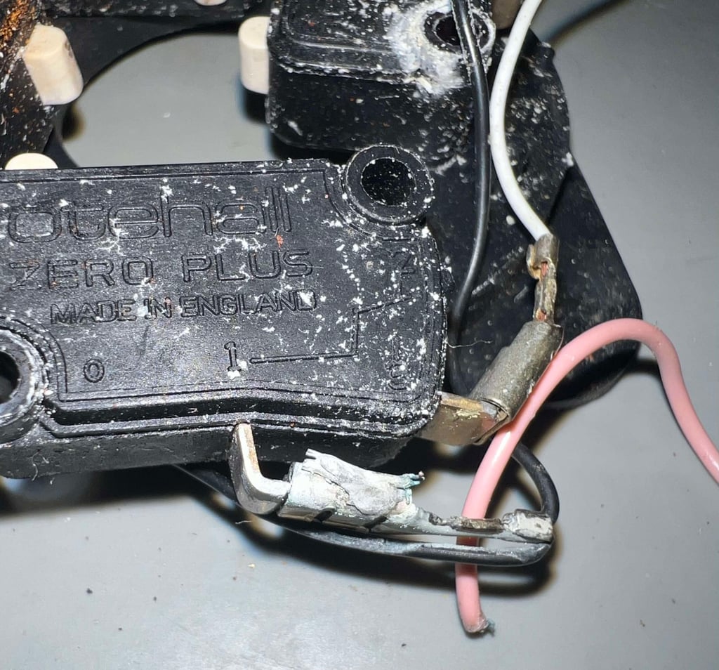
With the three screws out of the way the top cover is carefully lifted away. Well, it is actually not possible to lift it all away because the wires are too short (!). Also, I notice something wrong here. The plastic bracket which holds the four directional microswitches is turned upside-down. In addition I see quite a lot of corrosion on the switch toggling the autofire. No wonder it is stuck...
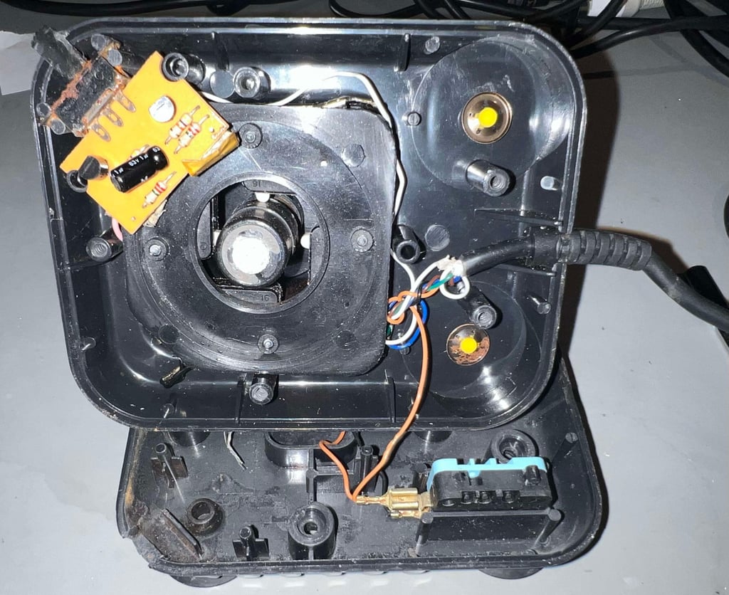


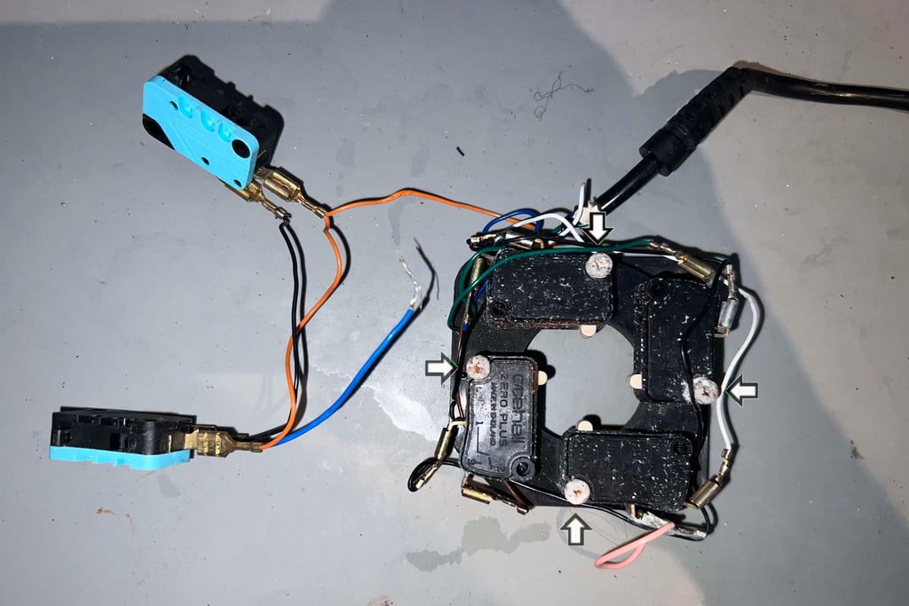
By some careful wiggling the four directional microswicthes are loosened from the joystick shaft. As can be seen from the picture below these switches are very dirty, but they do appear to be in ok condition nonetheless.
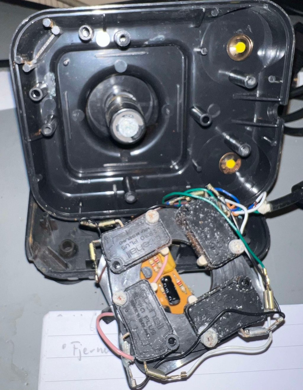

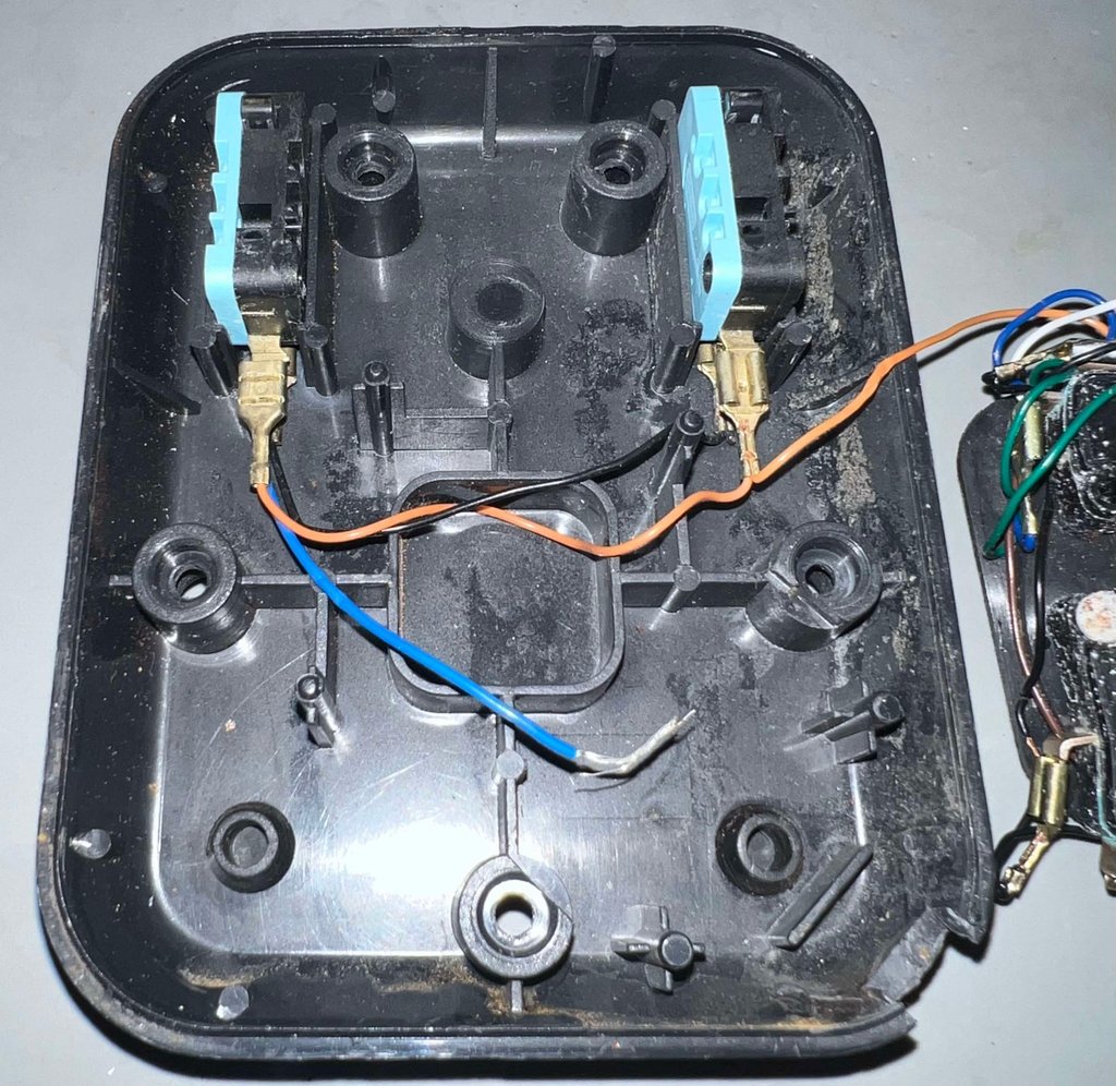
The bottom cover is now loose. And the same is the two fire button microswitches. Notice that there is a disconnected wire laying in the bottom cover. I am not quite sure, but I would assume this was once connected to the autofire PCB.

To disassemble the joystick shaft the E-clip is removed first by gently prying a small flat screwdriver in between the spaces.
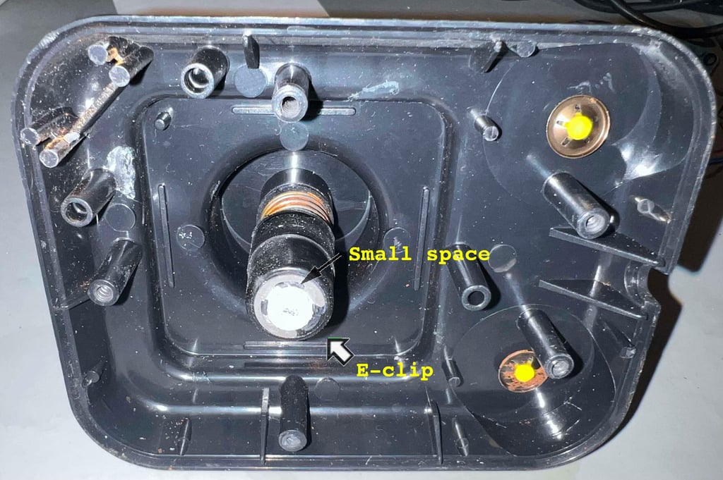

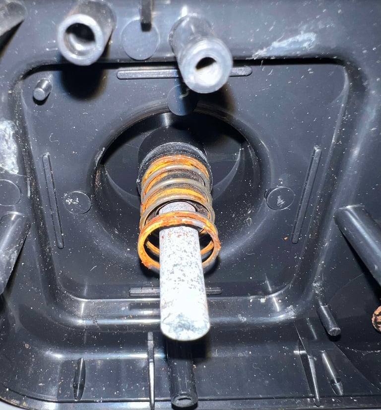
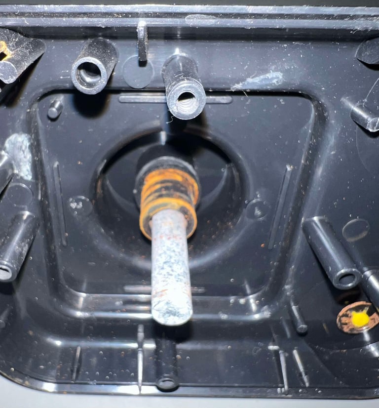
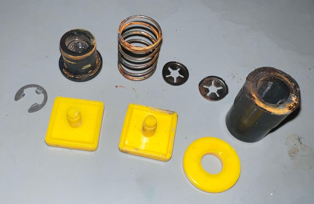
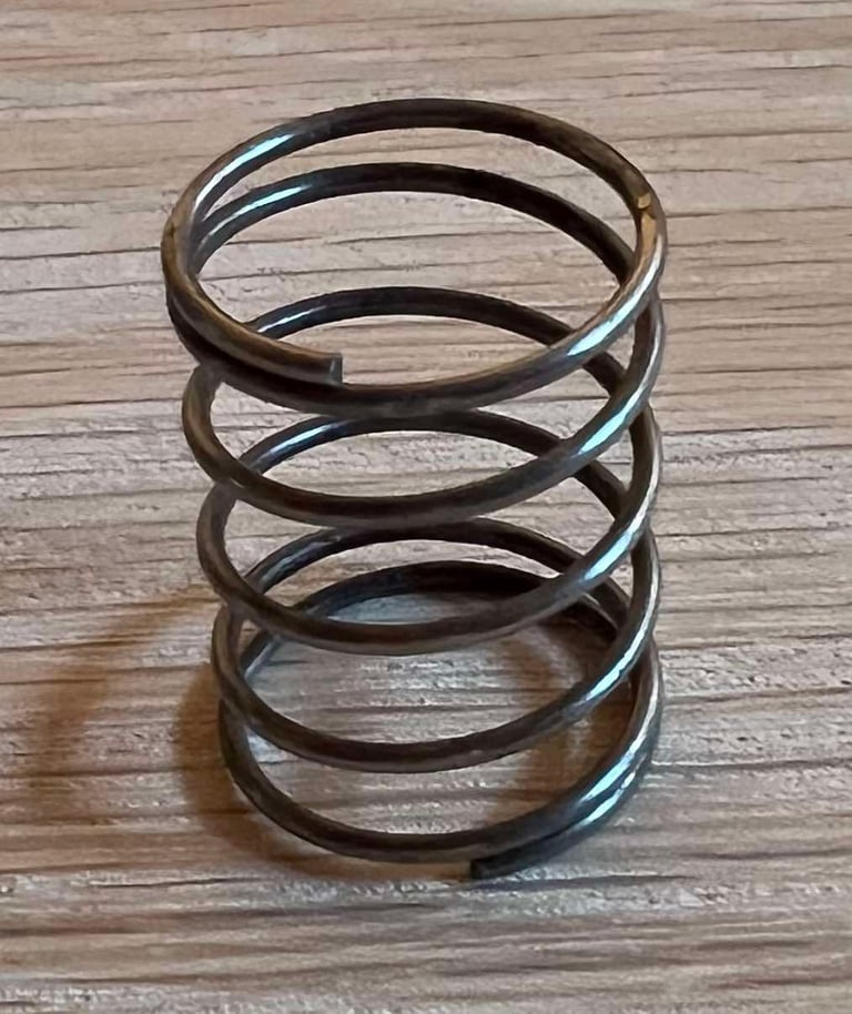
After the E-clip is removed, and the plastic spacer is removed, the spring is revealed. And holy moly it is rusted... In addition the rust has been smeared over the inner plastic spacer also. Hopefully, the spring can be revived by removing the surface rust.


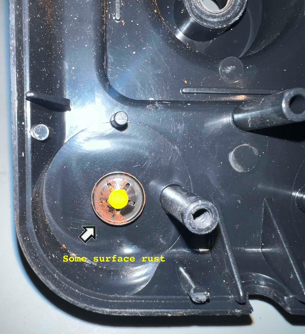
The two metal clips holding the fire buttons in place are removed. This is a bit tricky as the metal clips are both small and quite hard. But with a pair of pliers I manage to remove the clips. As can be seen from the picture below there are some rust on these also, but that does not worry me much. Their only function is to prevent the fire buttons from being pulled out - and some surface rust should not be much of a problem.

Finally, the four screws holding the directional microswitches are removed from the plastic bracket. Note that screw heads are severely oxidized so they are removed very gently to avoid any damage.

These screws have a different dimension than what is used to hold the covers: 3 mm x 16 mm. So it is good practice to keep these in a separate plastic bag when doing refurbish.

Exterior casing and plastic parts
Cleaning the parts
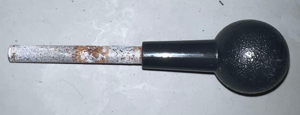
First, all the individual parts (plastic and metal) needs to be cleaned properly. Below is a picture of all the parts. As can be seen from the picture the parts are very dirty and the spring is very rusty.


All the parts, and also the top- and bottom cover, are placed in a plastic box filled with mild soap water. The parts are left for about 48 hours. This will dissolve most of the grease and fat.
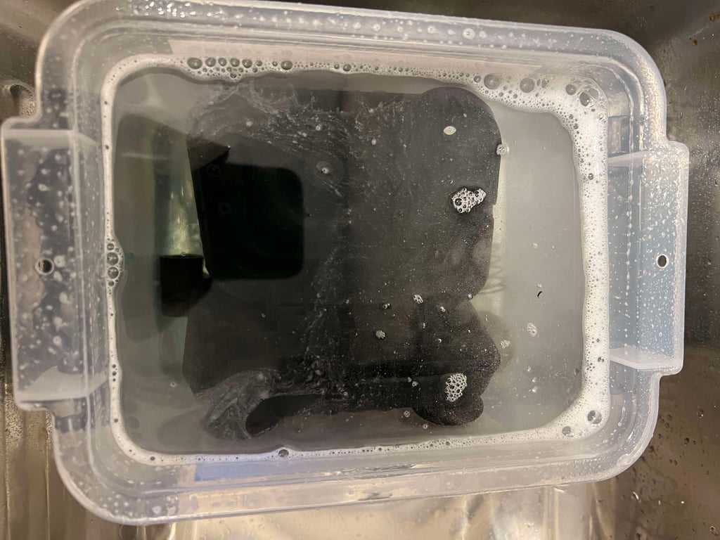

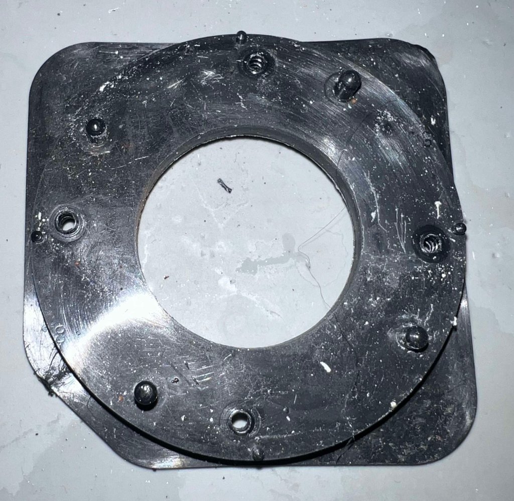

The plastic parts look very nice after cleaning. In addition to clean these with mild soap water, some glass cleaning spray is used also for the final touch.
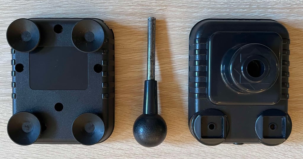

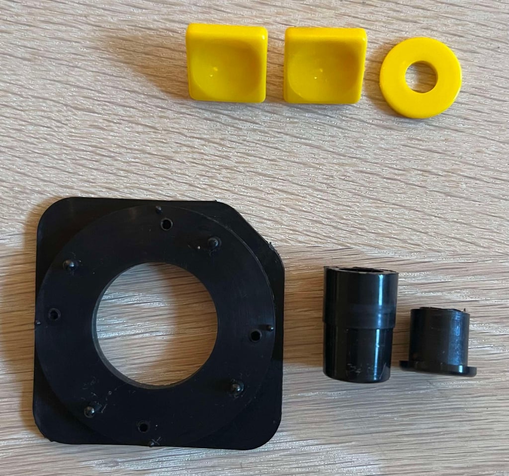

As mentioned the spring and screws are heavily rusted/oxidized. To remove this a combination of vinegar, isopropanol, WD40 and a steel brush is used. The metal parts are not perfect after this, but they are way better!


Lubricating the parts
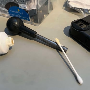
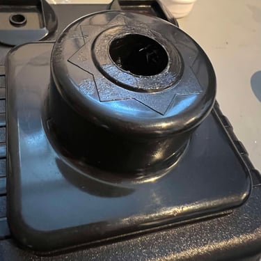
The Zipstik joystick requires the parts to move freely in order to operate flawlessly. Originally, the joystick has no lubricating at all, but I think it is good practice to lubricate some of the moving parts. This will make the parts move without much friction - the drawback could be that some more dust could stick to the grease but that is not a major issue.
A combination of multi purpose grease, silicone spray and sewing machine oil is used. The former is used for the more rugged parts such as the spring and joystick shaft, and the latter is used for the smaller moving parts such as the fire buttons.
Below is a gallery from the lubrication process (click to enlarge).
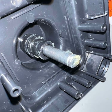
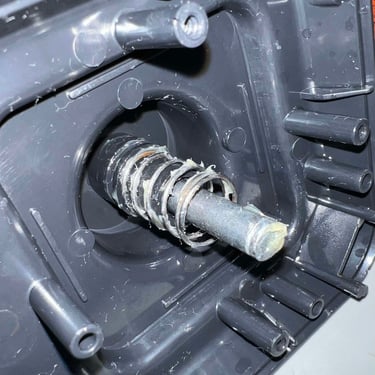
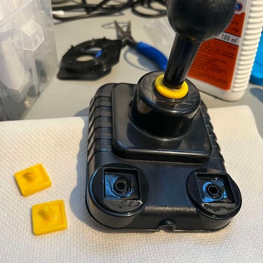
Since there was only three, out of five, screws holding the covers in place I add two more screws. These are not original, but they are cut to the same dimension: 3.5 mm x 13 mm.
Electronics and microswitches
Cleaning the microswitches
As seen from the disassembly section the microswitches are covered with dirt and grease. All of the microswitches are put in a jar filled with isopropanol for about 48 hours.
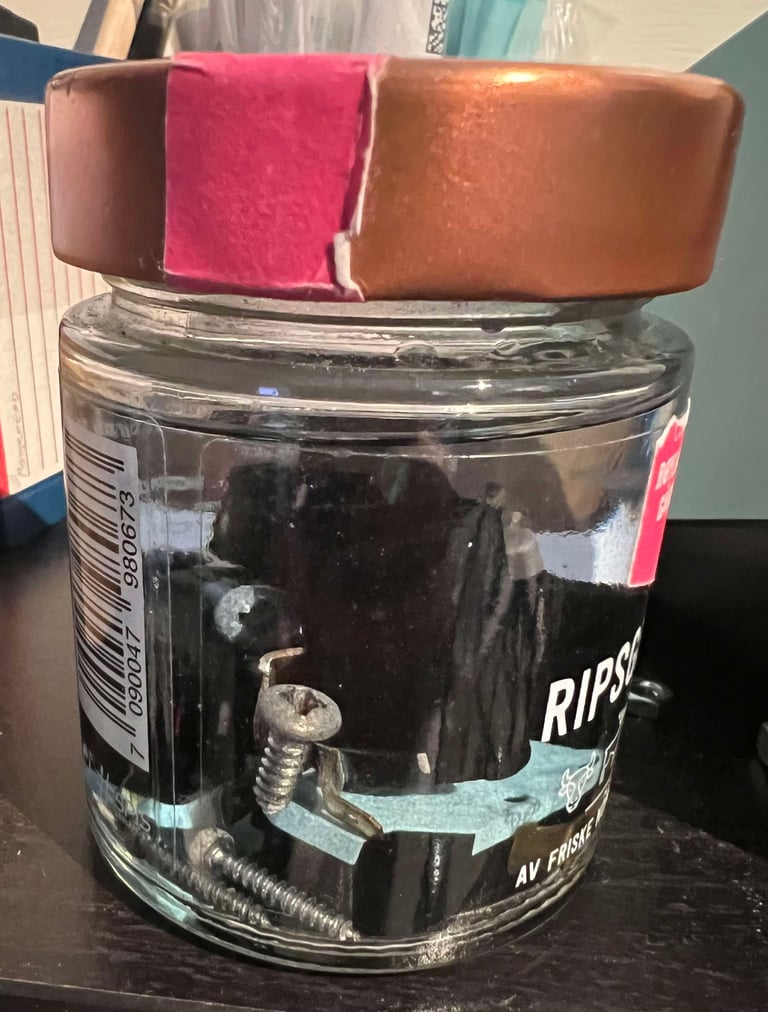

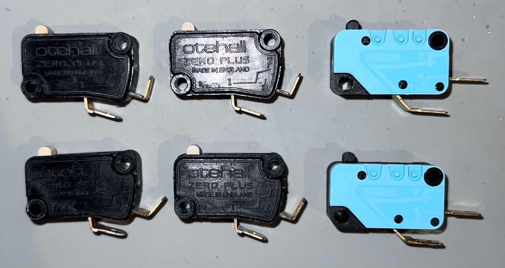
After the long bath each of the microswitches are rinsed with a Q-tip. As can be seen from the picture below they look very nice afterwards. Note that there are two versions used of the microswitches:
Otehall Zero Plus (made in England) for the directional motion (LEFT/RIGHT/UP/DOWN)
Crouzet (Made in France) for the two fire buttons


Replacing the cable and connector
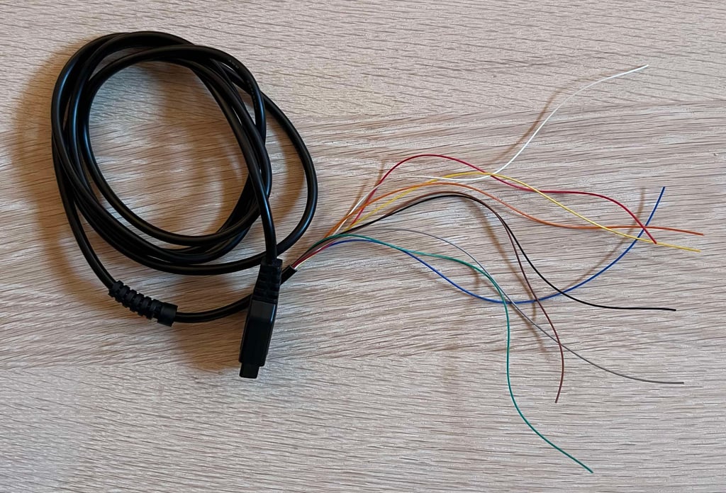
The cable and connector have seen better days. I don´t even bother testing it - instead replacing it with a brand new cable and connector. The strain relief is used from the old cable though.

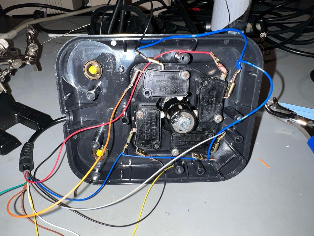
The old cable lugs are also used as these are in fact in quite good condition after cleaning. All the required wires are connected to the microswitches again. Note that this Zipstik does not use the +5 V wire (this is normal for the Zipstik even if it has an autofire function). Also, this time the microswitches and the bracket is placed in the correct way - not the way it was when the joystick was first opened.

Cleaning the PCB and replacing the electrolytic capacitor (NOT!)
The PCB is full of dirt, grease and old sticky tape. Yikes! And the switch to enable/disable the autofire function is severely corroded (and dirty). There is a 1 uF [63 V] electrolytic capacitor onboard the PCB.
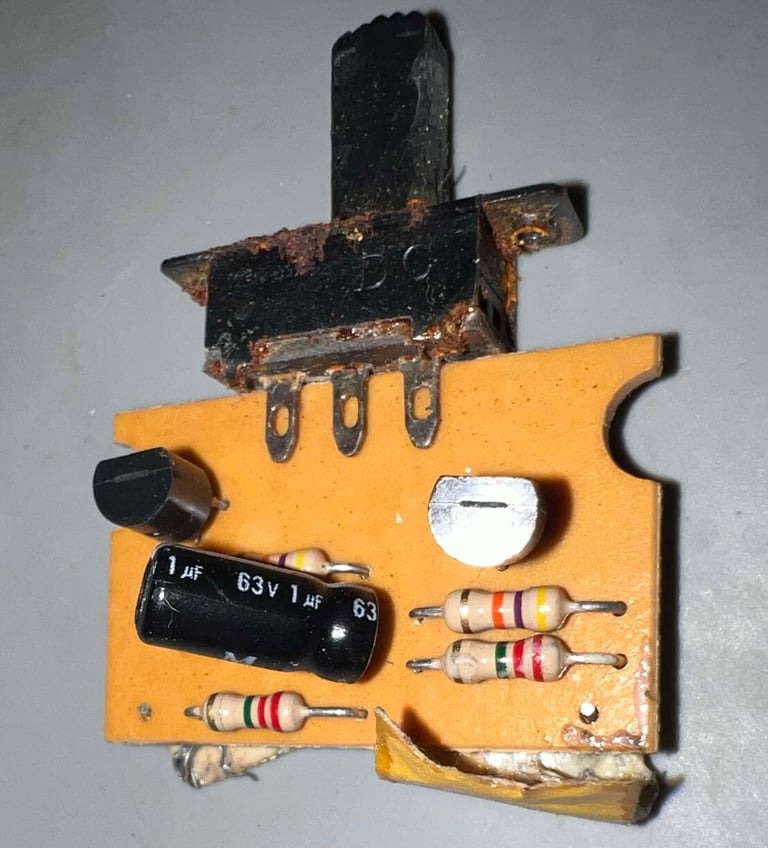

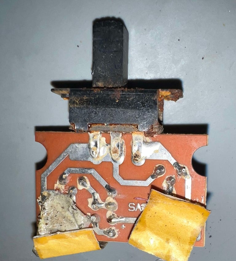

After cleaning the PCB, and the switch, looks way better. For cleaning a combination of isopropanol and contact cleaner is used. Now we can also see that the PCB is marked "SAF-2". What that means I don´t know, but I would not be surprised if the "AF" is short for "AutoFire".
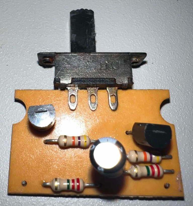

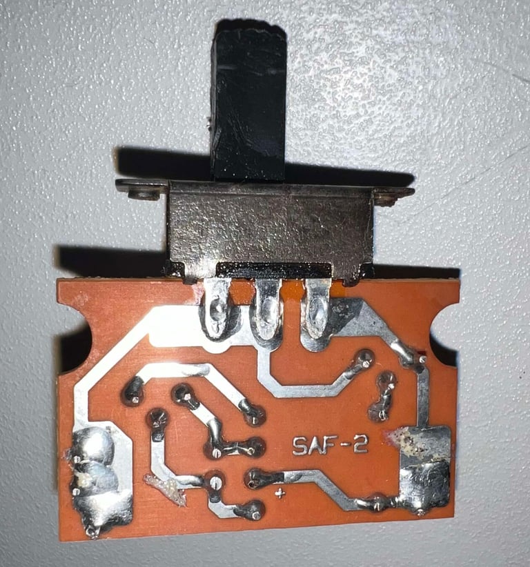

Since these old electrolytic capacitors can dry out I replace it with a new one. But now something odd happens... when doing a small test during the refurbish the autofire circuit doesn´t work! The 1 uF [63 V] is replaced with a capacitor of the very same rating, but it does not work at all. The autofire is completely stuck in "no fire at all" mode...
It turns out that when the old capacitor is put back in the autofire works perfectly! Why? I have no clue. I even try with another identical capacitor, but to no avail. The only thing I notice different is that checking the capacitor with a multimeter the old capacitor reads just below 1 uF. And the new ones about 1.2 uF. Could it be that in order for this circuit to work the exact value of the cap needs to be in place?
I decide to leave the old capacitor in. Now it works, and if it is correct that a slightly higher capacitance (>1 uF) prevent it from working it is better to have the old one in place. It is likely to loose some capacitance over age.
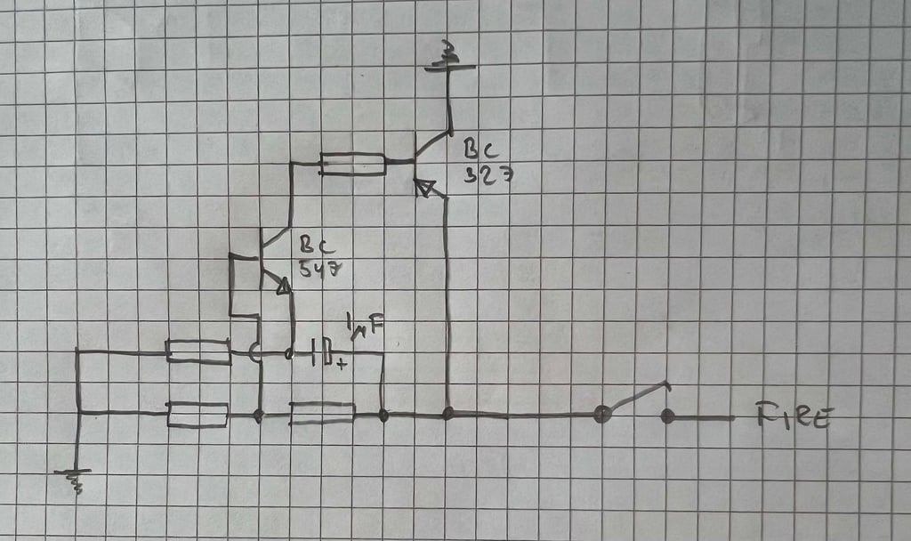
I made a short schematic of the SAF-2 circuit (hopefully this is correct):

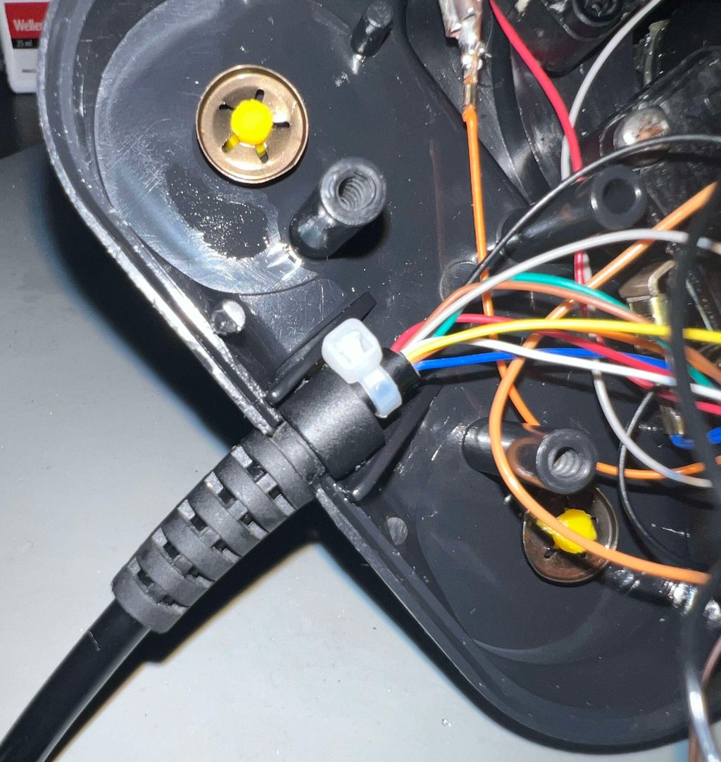
An additional strain relief (aka a cable tie) is placed next to the original strain relief. Since these joystick are often heavily used when playing great games, it is good to have some extra protection.

Testing
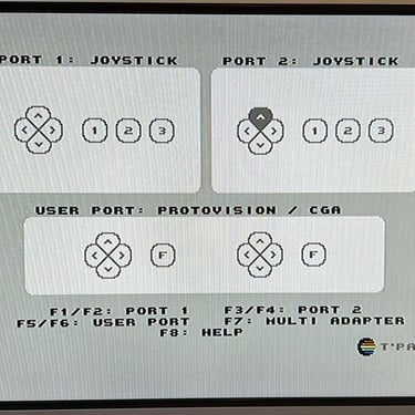
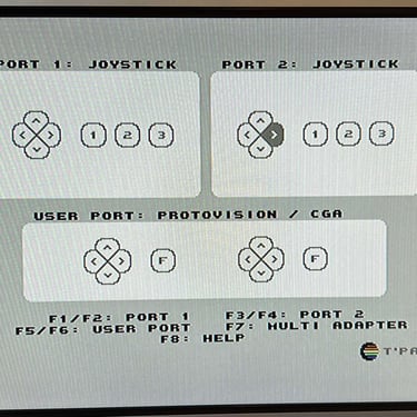
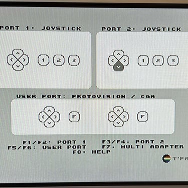
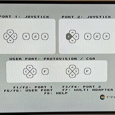
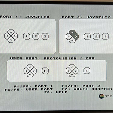
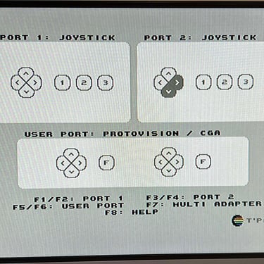
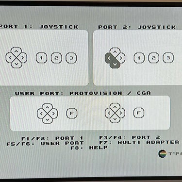
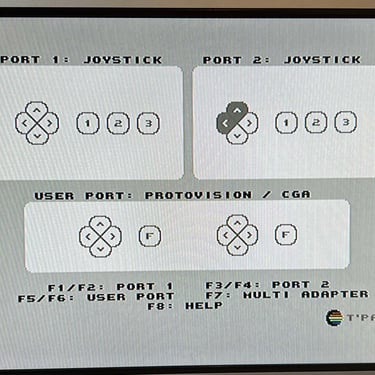
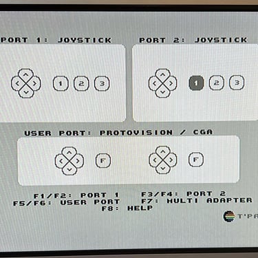
To verify that the joystick work as it should I check it with the Joyride software. Result is that all directions and fire buttons works fine works as expected. All tests pass.
Final result
"A picture worth a thousand words"
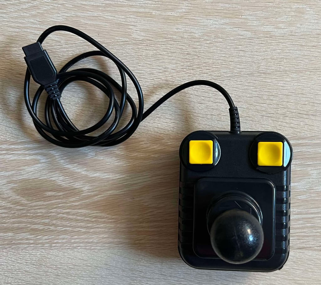
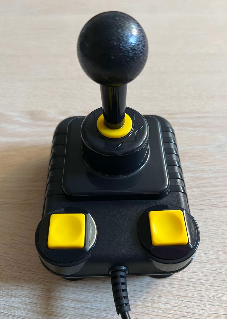
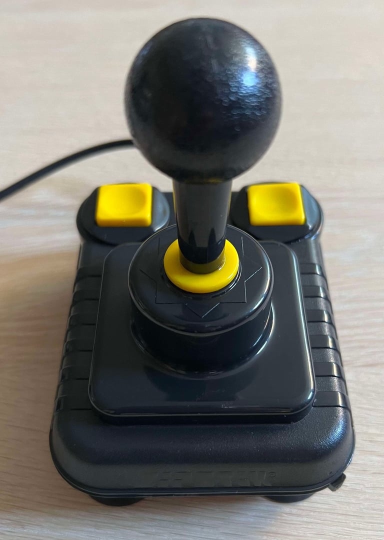
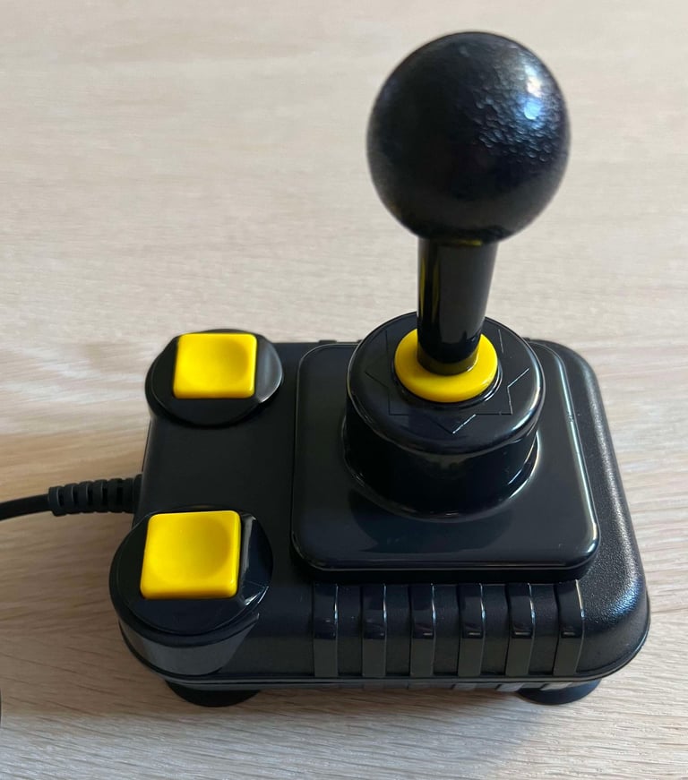
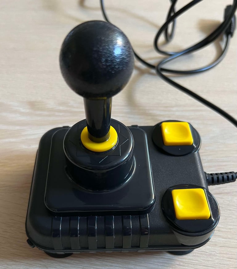
Below is a collection of the final result from the refurbishment of this Zipstik joystick. Hope you like it! Click to enlarge!






Banner picture credits: unknown
