

Zipstik
Starting point
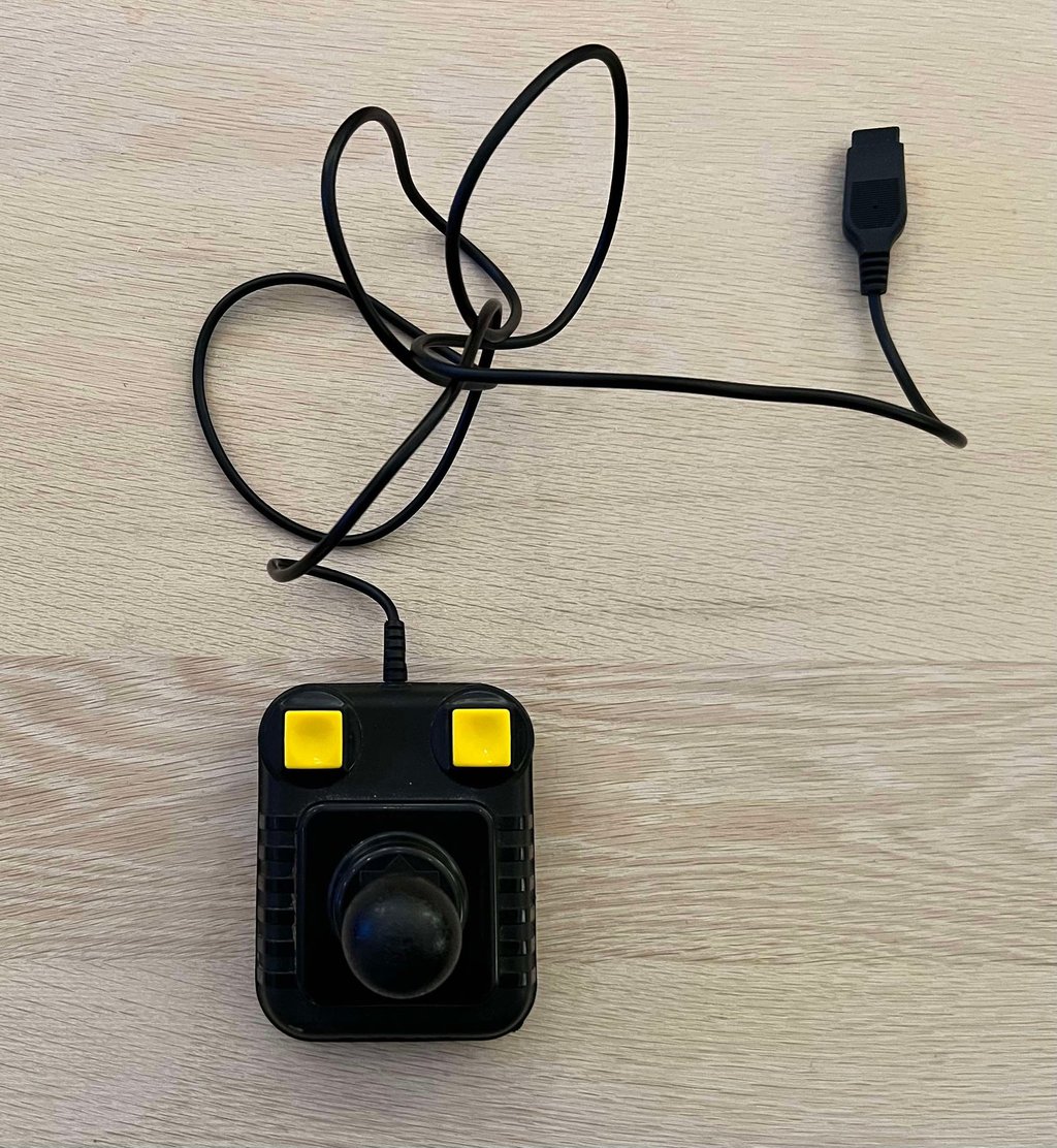
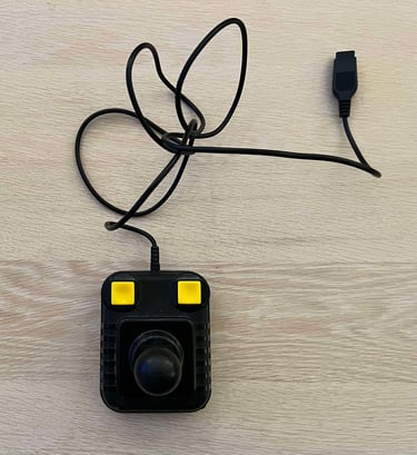
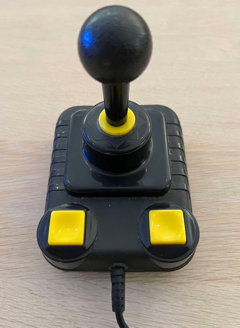
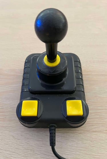
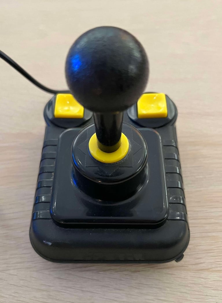
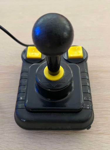
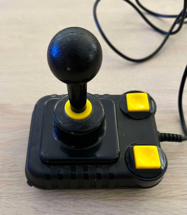
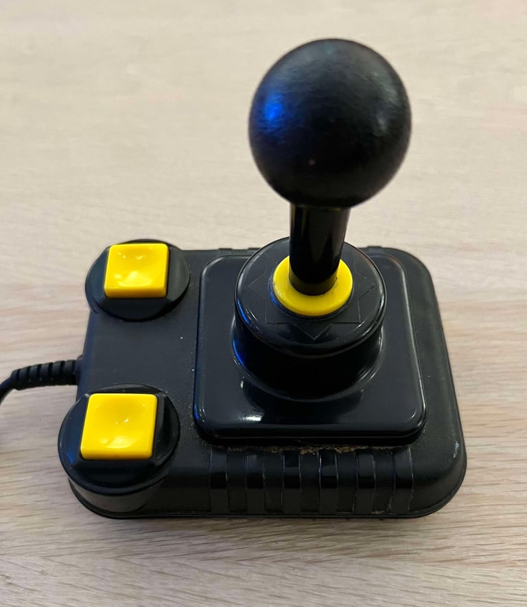
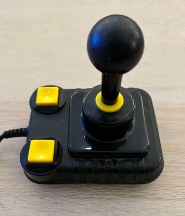
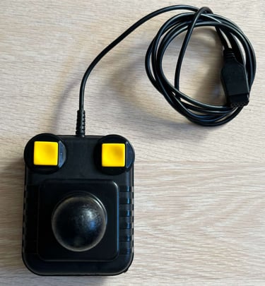
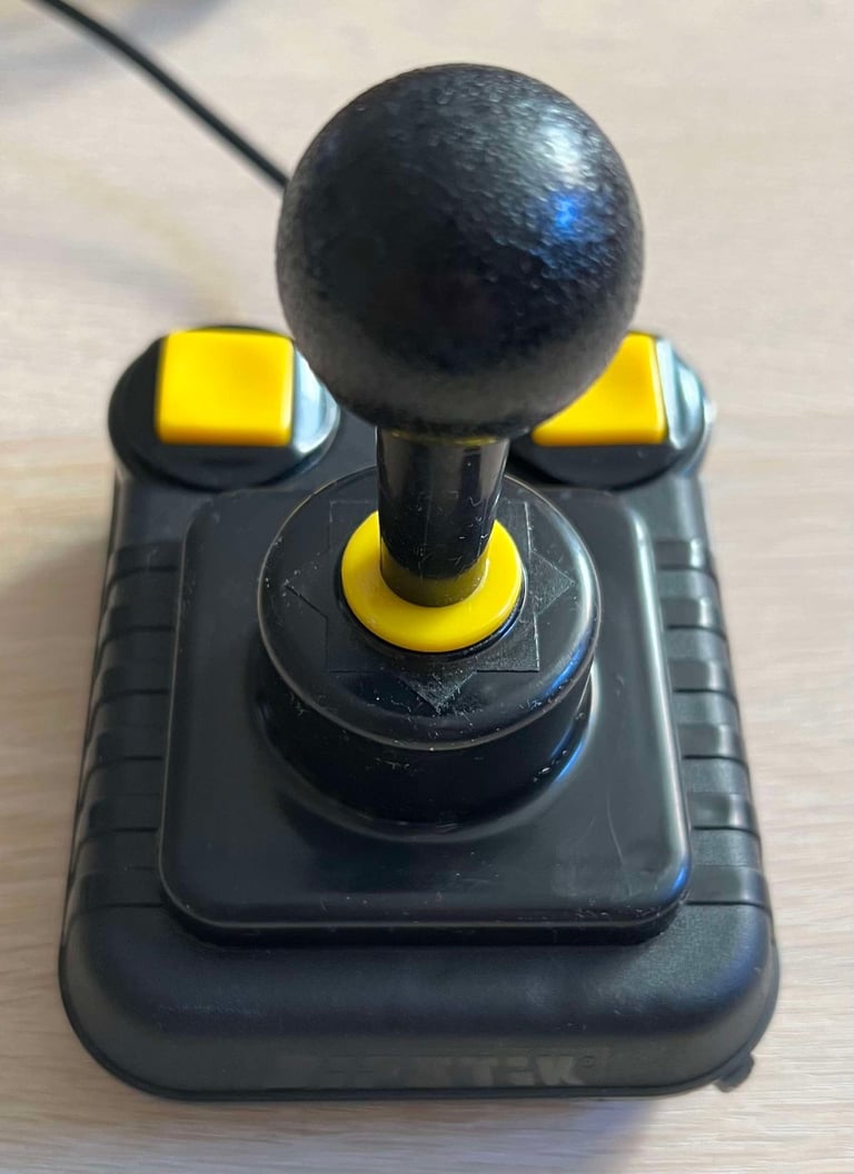
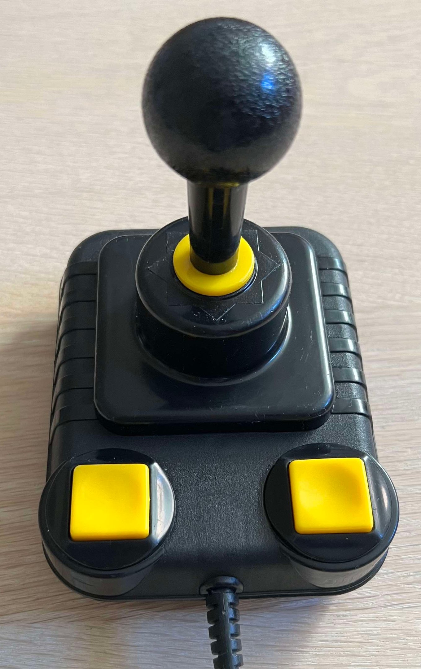
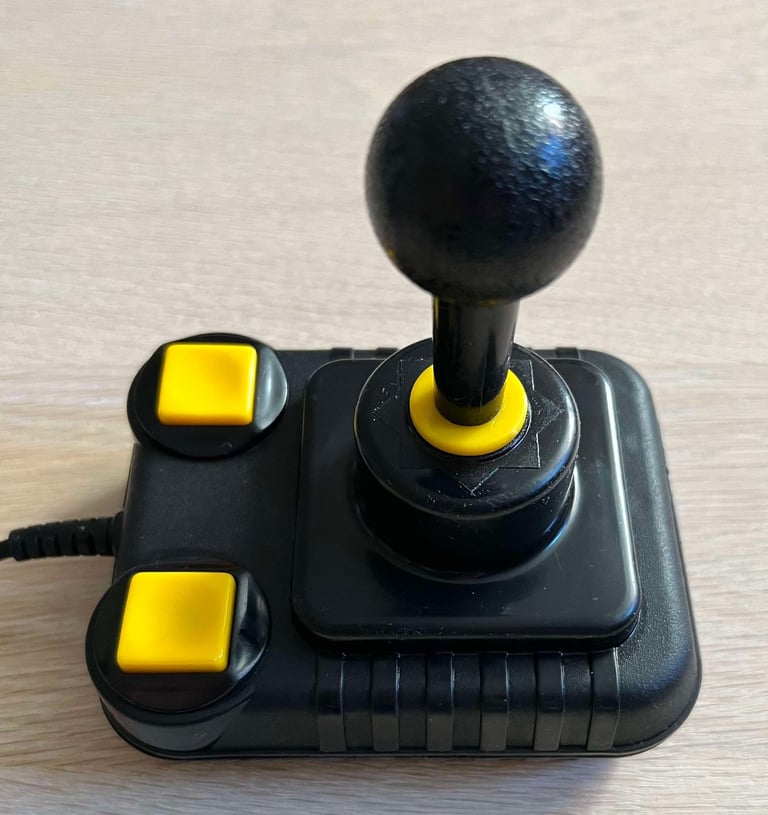
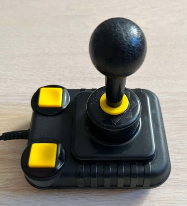
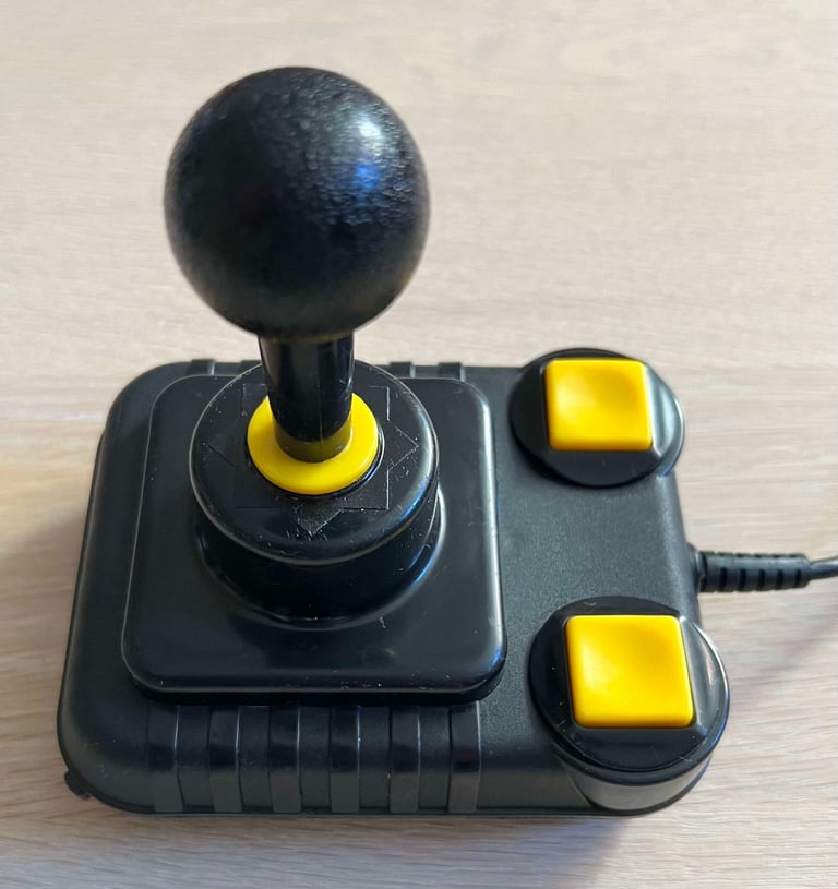
This joystick has come here for refurbish. According to the owner it´s not working as properly as it should, so I guess it could be related to poor contacts, switches or wires. From the outside it looks to be in very good mechanical condition. There are very few signs of use, only some light wear and tear. The cable, and also the connector, seems to be in good condition.
But there is something I notice: it feels that the plastic used in this Zipstik is somewhat different than other Zipstick joysticks I have repaired. Its almost like it is a bit softer to the touch. My guess is that it could be either a very late, or early, version - or produced at a smaller factory. I find these things very interesting!
Another thing which is quite notable is that the felt resistance of the six microswitches are higher than other Zipstiks. The sound from the microswitches is PERFECT, but the force you need to use to push the buttons, and moving the shaft in the different directions, are higher than I have seen before.
The joystick is equipped with an AUTOFIRE switch, and the switch itself seems to be in good condition.
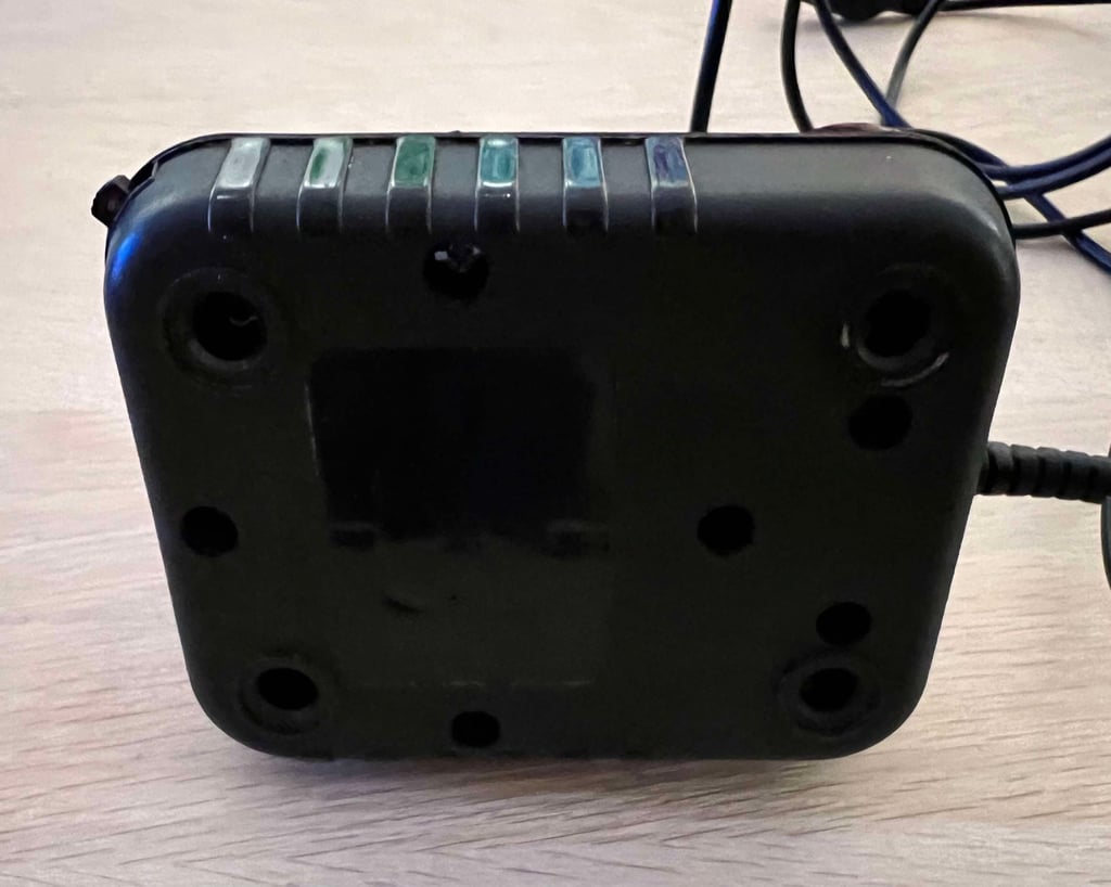
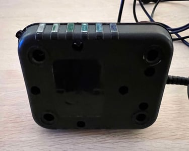
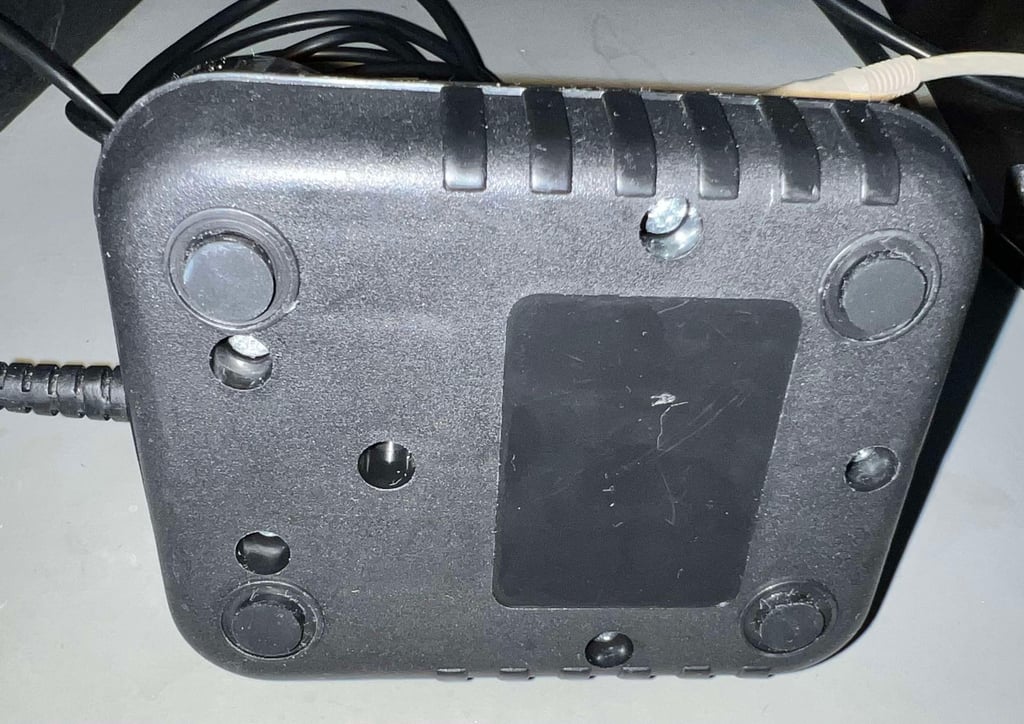
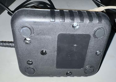
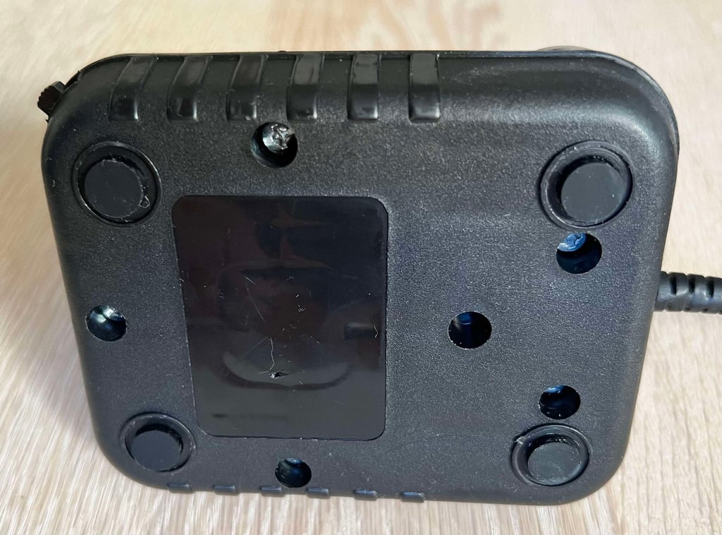
None of the four rubber feet are present. All of them are removed and you can see inside of the joystick through the four small holes where the rubber feet used to be.
Below is a picture of the Zipstick before refurbish.

Refurbishment plan
To refurbish this joystick the plan is to do this trough the following steps:
- Clean, and remove stains from, chassis and all parts (and repair if required)
- Lubricate moving parts
- Clean and check the microswitches (and repair if required)
- Clean and check autofire PCB (and repair if required)
- Check connectivity (and repair if required)
- Verify joystick operation by testing
Disassembly
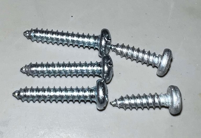
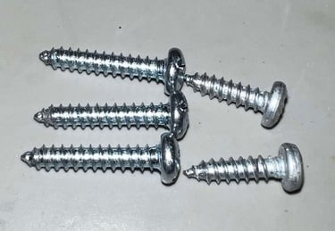
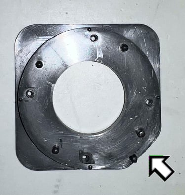
The Zipstik consists of a top- and bottom cover helt together with five screws at the bottom side. Now I notice something; two of the screws are a bit more oxidised and have a different screwhead. In the picture below, the blue squares contains screws with Pozidrive heads. The yellow squares contains screws with a combined Phillips/flat head. Is this original? I really don´t know - maybe.
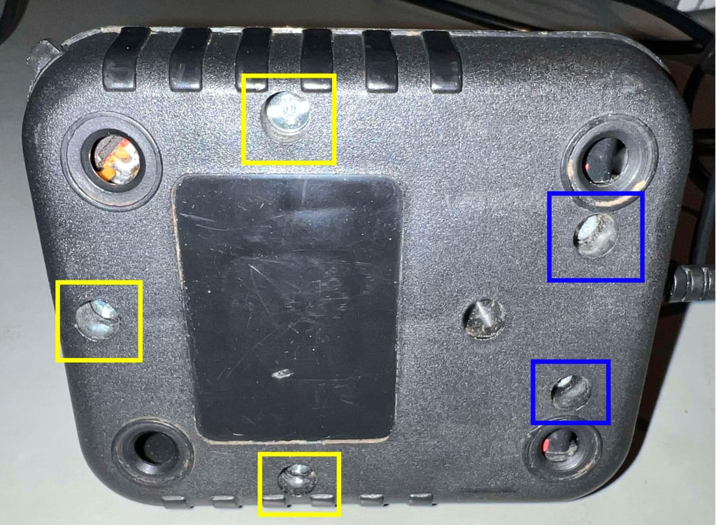

With the screws out of the bottom another interesting (?) finding is done: they not only differ in screwhead type, but also in length. My gut feeling is that some of these screws, either the long or short, have been replaced at some time. But I could be wrong. The screws are: 3.5 x 13 mm (Pozidrive) and 3.5 x 18 mm (Phillips/Flat). Even if there are some slight oxidation on the top of the Pozidrive screws they are in fine condition.
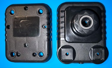
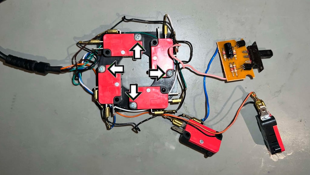
The top cover is carefully lifted, and the interior is exposed. And this is a surprise for a Commodore nerd like me, holy moly:
Never seen these kind of microswitches. Usually I find mircoswitches from Otehall and Crouzet in Zipstik.
The plastic parts mounted on the bottom of the joystick shaft is different from what I have seen before in Zipstik
And already mentioned; the plastic "feels" softer and a combination of different screws at the bottom
There is very little dust and grease inside the joystick. And I can not see any kind of immediate damage to any parts. But there is something I notice which needs to fixed:
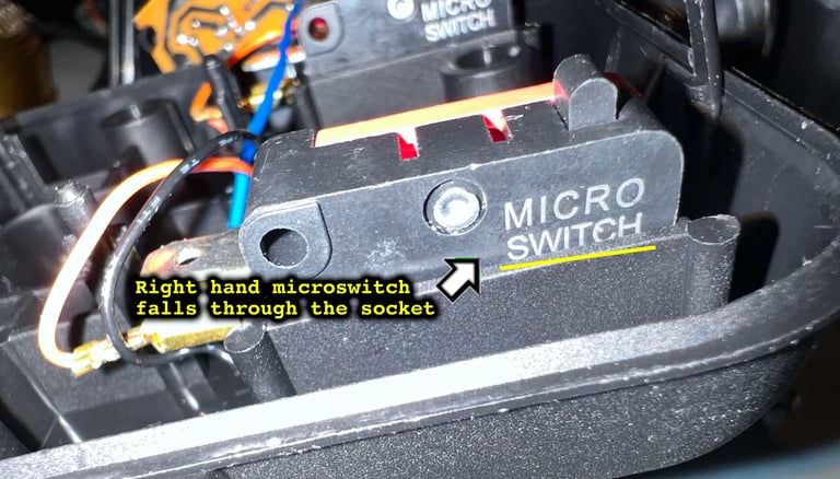
The right hand side FIRE button microswitch has one of the wires stuck next to the thin plastic supporting wall. I would guess this has happened during prodution (or if someone has been here before). This needs to be fixed because the wire could rip during use, and the plastic supporting walls needs to be very precisely aligned to hold the microswitch in right position.

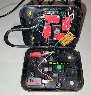
Below is a picture of the microswitch the the wire is stuck. As can be seen the left plastic wall is pushed outwards, and this will damage the supporting function of the wall - the wall will not be able to keep the microswitch in the correct place.

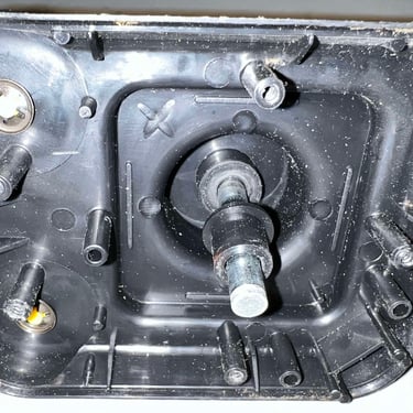
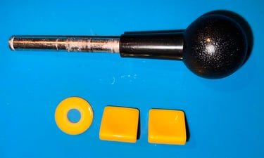
All the microswitches, and the autofire PCB, are lifted away from the top- and bottom cover. This reveals the bottom assembly of the joystick shaft which looks to be in good condition (it is quite dirty, but that is to be expected). To start the disassembly of the joystick shaft the E-clip is removed.
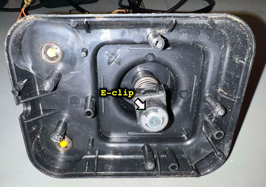

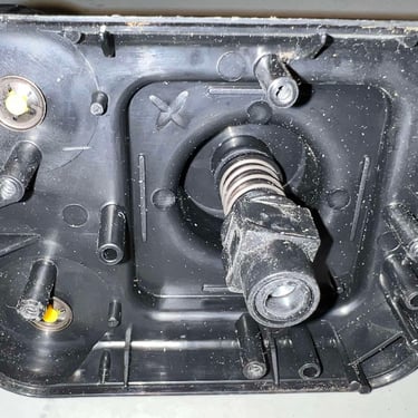
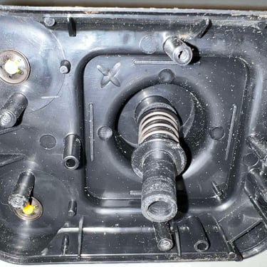
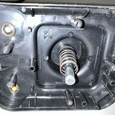
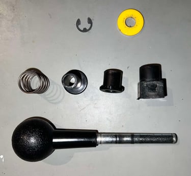
Removing the rest of the shaft parts is just a matter of pulling them off one by one. Make sure to take note of the order the parts are mounted. Below is a picture gallery from the disassembly of the joystick shaft.

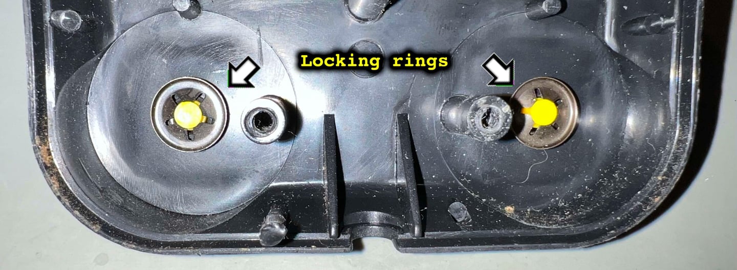
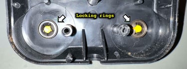
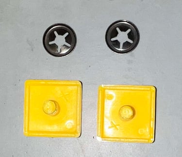
To remove the FIRE buttons the two locking rings have to be carefully pried off. I use some fine pick tools to gently lift the locking ring off the FIRE button plastic stem.

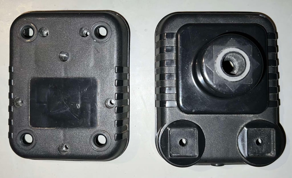
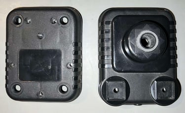
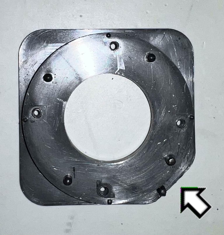
Below is a picture of the top- and bottom cover before going for a long awaited bath.
Exterior casing and plastic parts
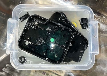
All the plastic parts, and the metal joystick shaft, are placed in a box filled with mild soap water for about 24 hours. This will dissolve most of the grease from the parts.

After cleaning the parts look good as new. All the grease and dirt are gone.


Repairing the bottom cover - microswitch socket
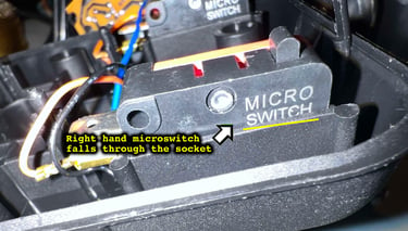
As previously mentioned the area where the right FIRE button switch is socketed is damaged. Due to a wire which has been stuck between the microswitch and the supporting plastic wall, the microswitch fall through.
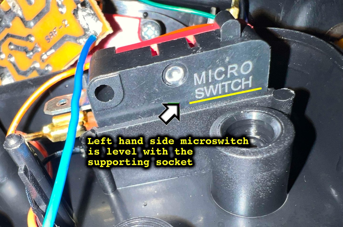
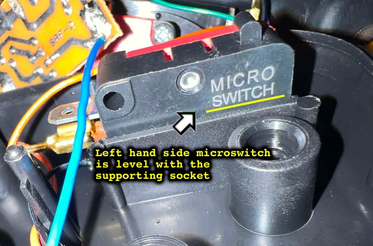
Below are two pictures; one showing the left FIRE button microswitch and one showing the right FIRE button microswitch. Notice how the text "MICRO SWITCH" is level, and aligned, to the supporting wall on the left FIRE button microswitch. But on the right it "falls" through the supporting plastic wall. In the pictures a thin yellow line is drawn to illustrate this.
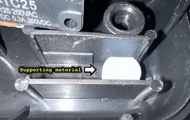
To repair the socket a piece of glue (not melted) is cut to size. This should work very well as it is more than strong enough to support the switch, and also soft enough to not do any damage to the supporting walls.

Lubcrication
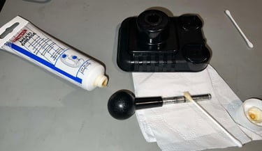
Although not strictly required, I think it is good practice to lubricate some of the moving parts. This is to reduced the friction between the metal and the plastic parts which will be rubbed against each other during operation. To lubricate the parts some multi purpose grease is used.

Adding rubber feet
Four new rubber feet are added. This joystick was probably equipped with suction cups originally, but instead of replacing these some small thin (3 mm) rubber feet are used.
Electronics and microswitches
Disassembly
Four of the microswitches, used for LEFT/RIGHT/UP/DOWN, are mounted on a plastic bracket with 3 x 16 mm Pozidrive screws.

Note that one of the corners of the plastic bracket are different. This corner has to be in the right bottom corner of the top cover (seen from underside - and the FIRE buttons to the left).
For easier access to clean the autofire PCB, and change the electrolytic capacitor, the two wires connected to the PCB are desoldered.
Cleaning and inspection - microswitches
Each of the microswitches are cleaned with isopropanol. Also, some contact cleaner is sprayed in the small openings of the switches and the button is "massaged". I can not see any damage to the switches. They feel really good. They are much harder to press than the Crouzet or Otehall usually found in these joysticks, but I think that is quite good.
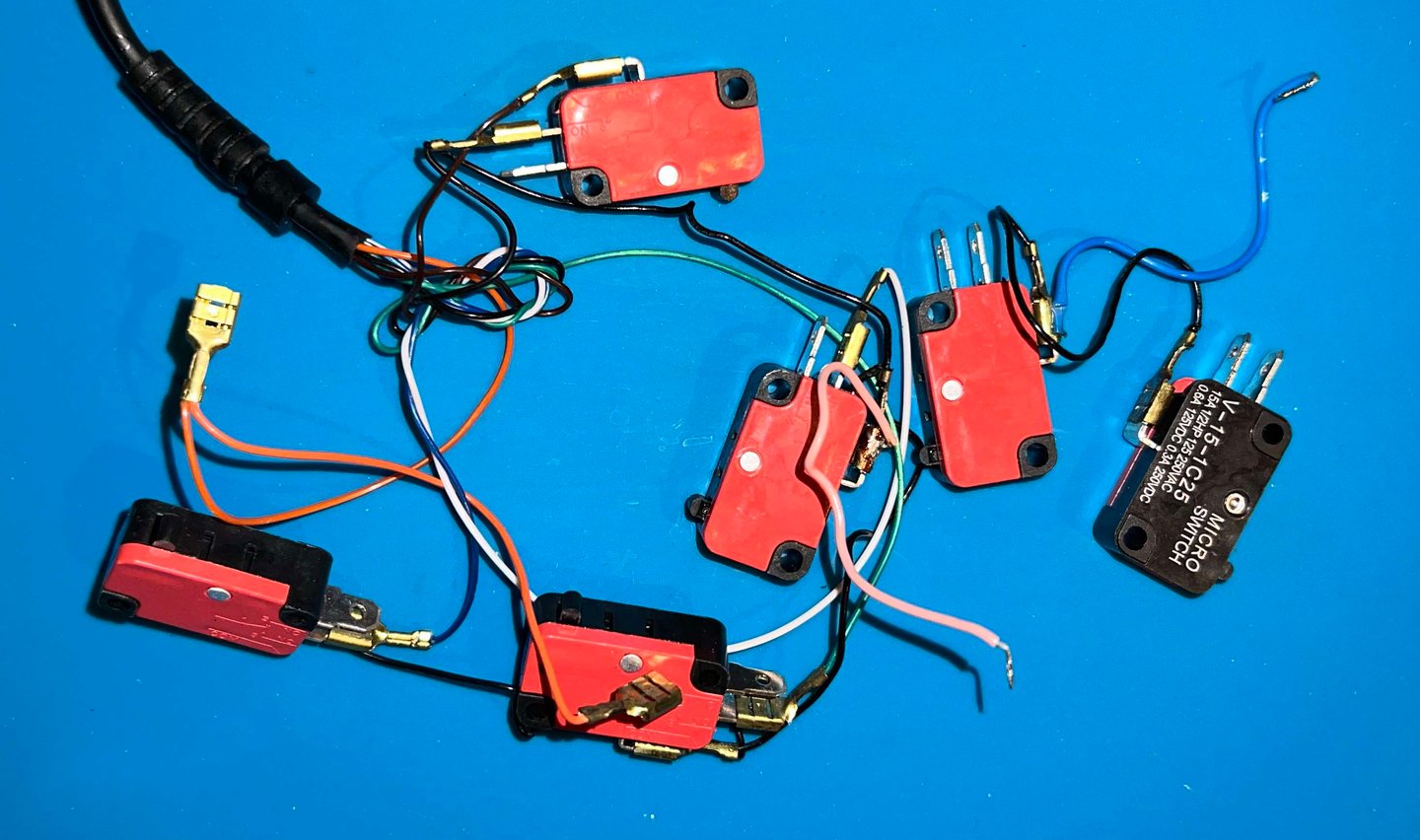

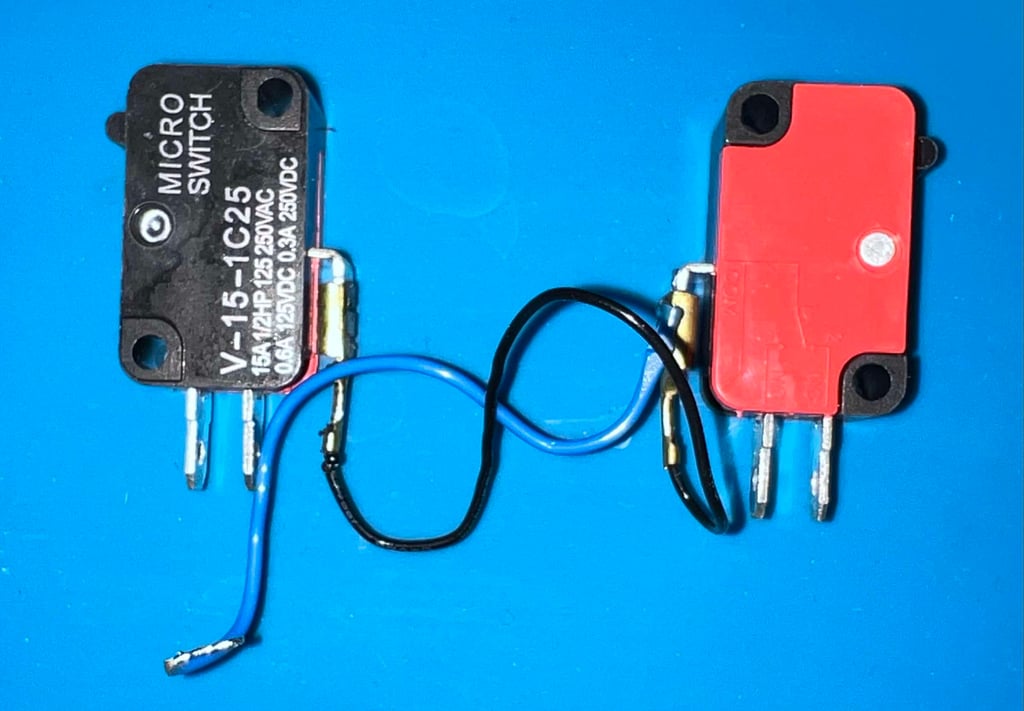
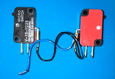
So what brand are the microswitches? They are marked with "MICRO SWITCH" and "V-15-1C25". After a quick Google search I find that Omron Electronics make such microswitches with the same number! So I think it is fair to say that they could be from Omron.
Cleaning, inspection and replacing the capacitor - PCB
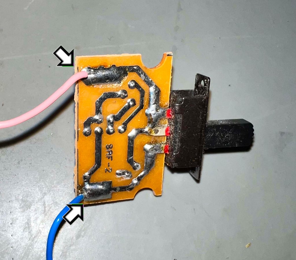
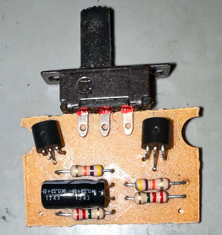
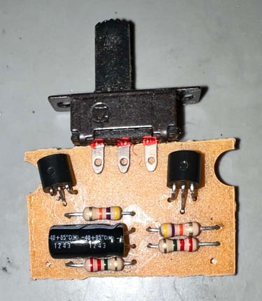
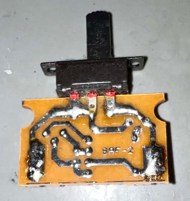
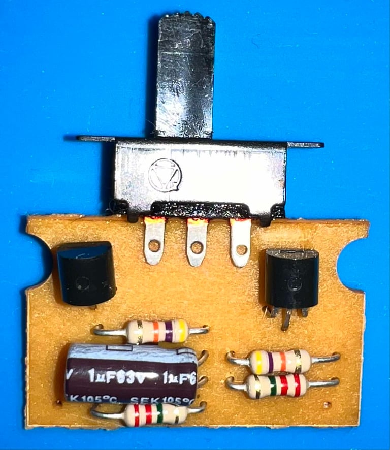
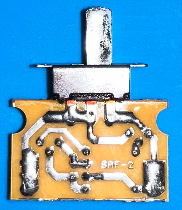
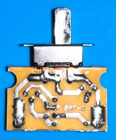
This is a SAF-2 version of the Zipstik autofire PCB. Equipped with a switch, two transistors, some resistors and one 1 uF [63V] electrolytic capacitor. It is quite dirty, both with flux residue and grease. But other than that it does seem to be in fine condition.

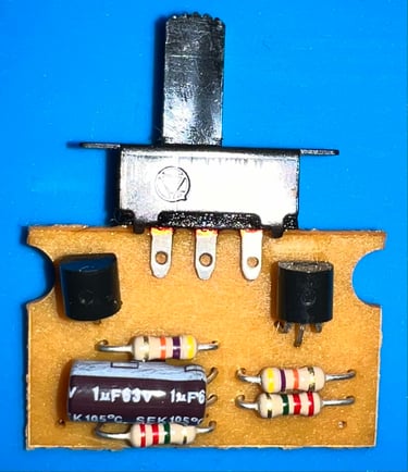
The 1 uF [63 V] electrolytic capacitor is replaced with a modern replacement - same capacitance and voltage rating. Finally, the PCB is cleaned free from all the dirt and grease.
Checking the connectivity
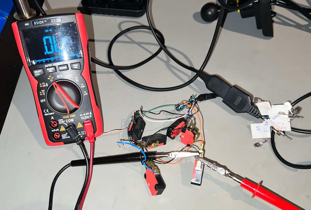
It is good practice to check the connectivity of all the wires in the cable before the joystick is assembled. This is because it can be hard to detect a marginal wire when everything is re-assembled. With a multimeter in continuity mode all the wires are checked, and pass fine.
UPDATE - SMALL REPAIR
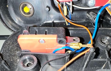
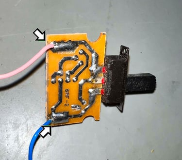
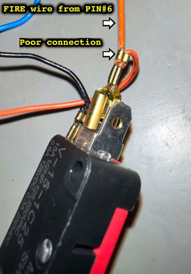
During use it is discovered that the FIRE buttons does not work any more. None of them. It turns out that the FIRE wire (PIN #6) entering the joystick is not making good contact with the micro switch. This is something I normally detect by testing the wires (as shown in the picture above) while the wires are moved around. But this one seems to have tricked me. Below is a picture of the troubled wire before repair.
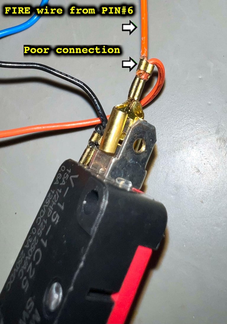
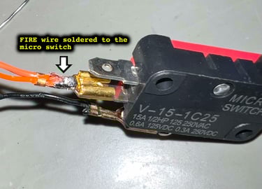
The broken part of the wire is cut and soldered to the micro switch. This should make a proper lasting connection.

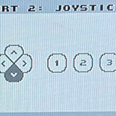
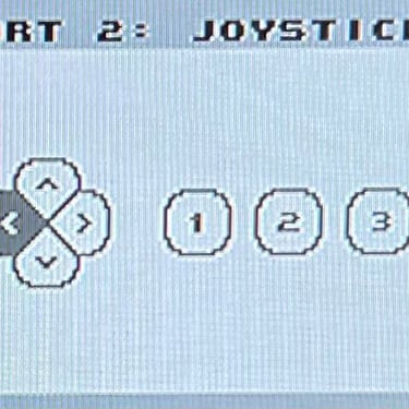
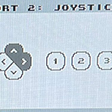
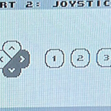
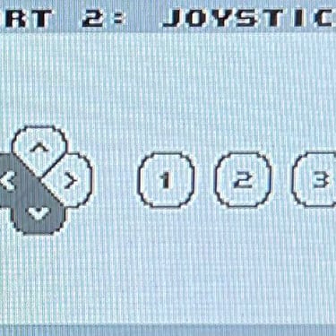
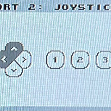
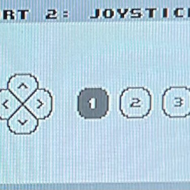
Testing
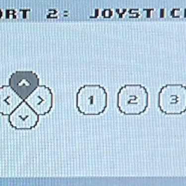
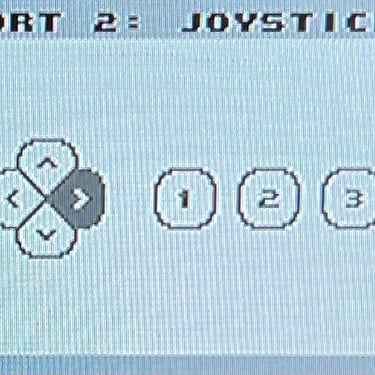
To verify that the joystick work as it should I check it with the Joyride software. Result is that all directions and fire buttons works fine works as expected. All tests pass.
Final result
"A picture worth a thousand words"
Below is a collection of the final result from the refurbishment of this Zipstik joystick. Hope you like it! Click to enlarge!


Banner picture credits: unknown