
Zipstik
Starting point
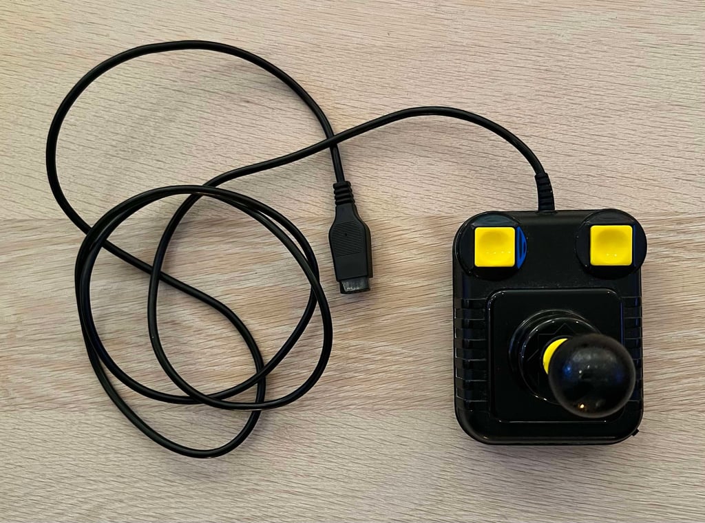
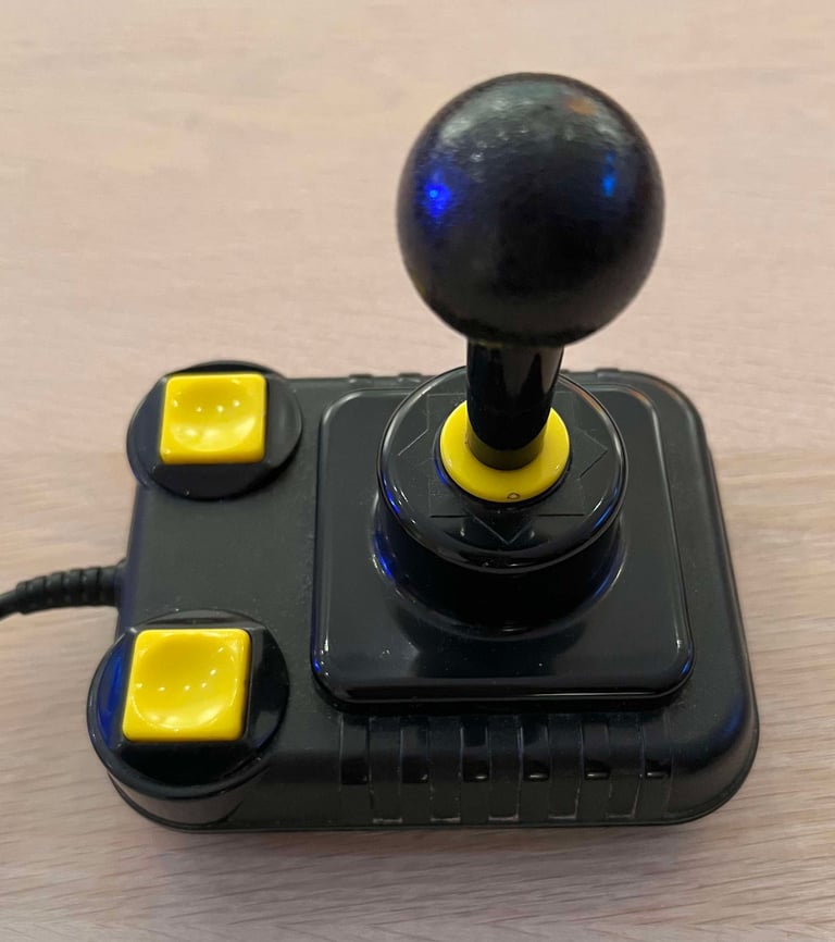
"Not bad at all!" would be adequate to describe the first impression. This is the first in a series of two which are in for some refurbish. The microswitches are reported to be a bit "flaky" from time to time, but this could very well be just caused by bad contacts or mechanical issues.
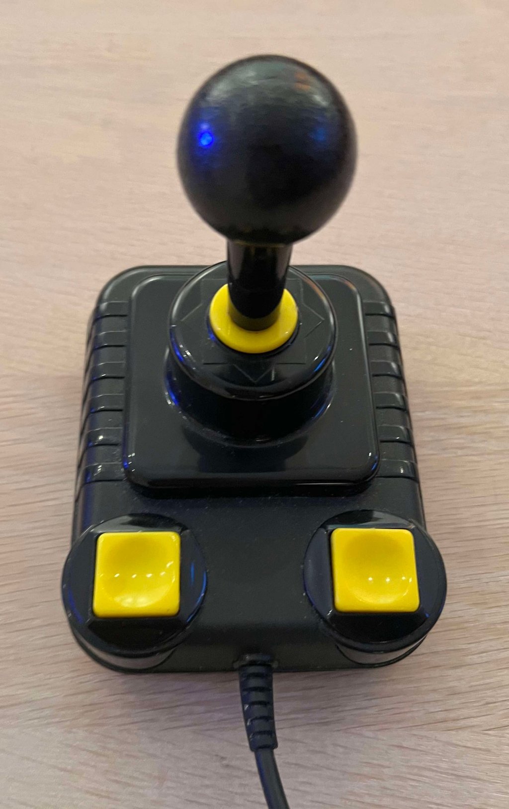
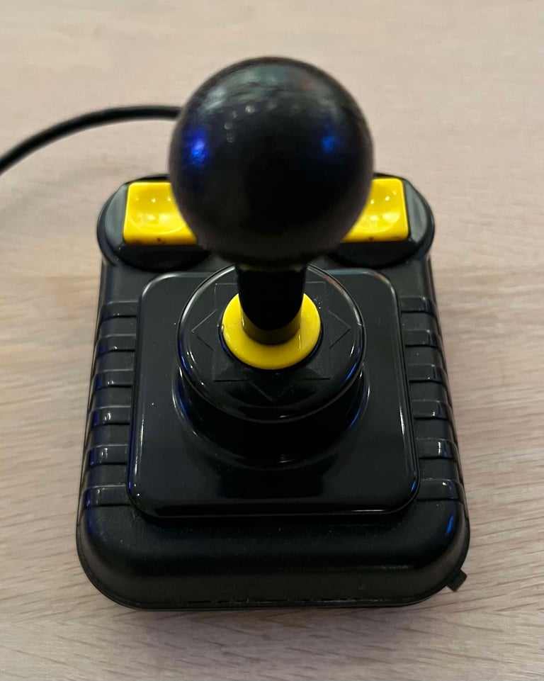
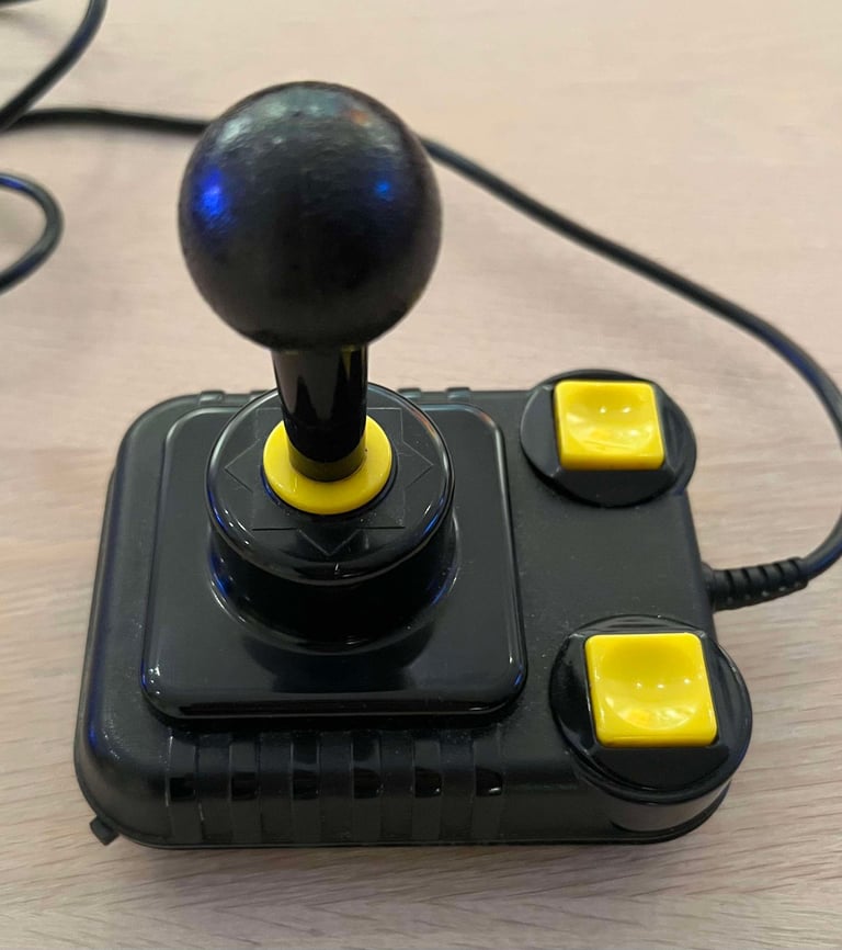
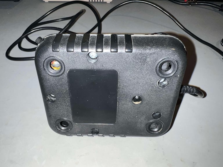
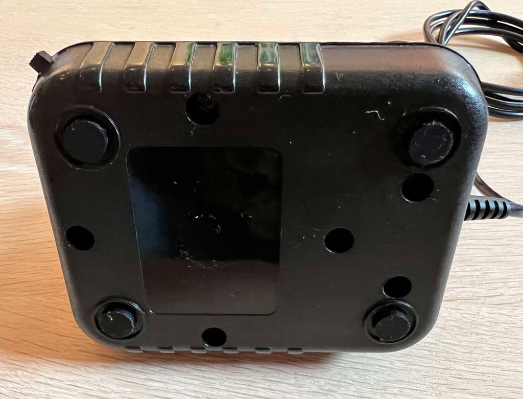
There is some dirt and grease on the outside, but not nothing severe. The sound from the microswitches seems to be ok, but that does not imply that they actually work as they should. Also, the autofire switch appears to be mechanical ok. Both the cable, contact and strain relief seems to be in good condtion. All-in-all I can´t see any significant damage or issues from the exterior of this joystick. The only thing that is missing is the four suction cups at the bottom, but these are removed intentionally.
Below are some pictures before the refurbish.






Refurbishment plan
To refurbish this joystick the plan is to do this trough the following steps:
- Clean, and remove stains from, chassis and all parts (and repair if required)
- Lubricate moving parts
- Clean and check the microswitches (and repair if required)
- Clean and check autofire PCB (and repair if required)
- Check connectivity (and repair if required)
- Verify joystick operation by testing
Disassembly
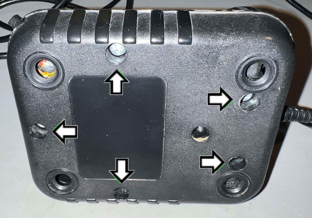
Disassembling the Zipstik starts with removing the five Pozidrive 3.5 x 13.5 mm screws. This will allow for the separation of the top- and bottom cover.

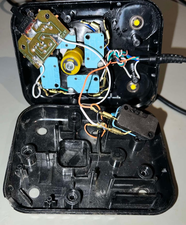
The top cover is carefully lifted away from the bottom cover. Note that the wires connecting the FIRE microswitches are a bit short, so it is wise to be a bit gentle when opening to avoid damage. There is quite some dust inside the joystick, but this is to be expected. But otherwise the first impression is good - I can not see any immediate damage or issues.

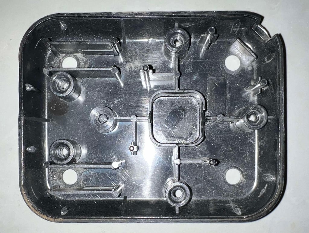
The bottom cover is in good condition, except for some dust and grease. None of the stems appears to be broken.

To disassemble the joystick shaft the E-clip located at the end of the rod is removed first. Then each plastic part, and the spring, is removed one-by-one. Make sure to make note of the sequence of disassembly, so that the re-assembly is done correctly later. Below is a little picture gallery of the disassembly of the shaft.
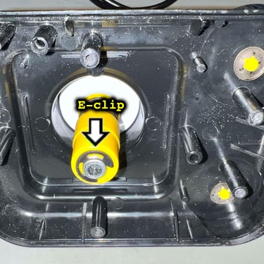
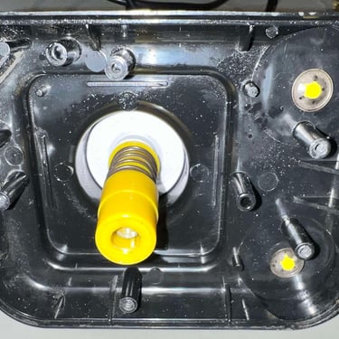
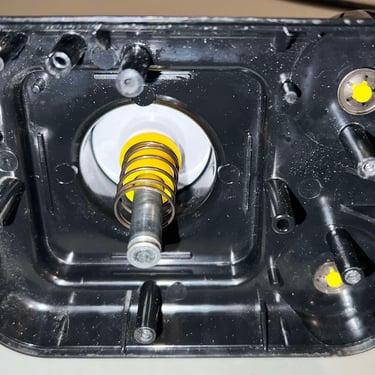
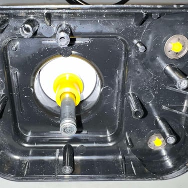
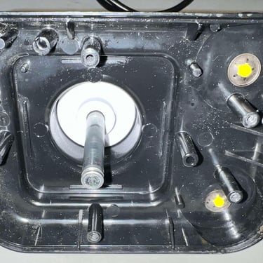
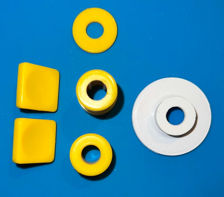
As with the bottom cover, the top cover and the joystick shaft are in good condition (except for dirt and grease). Only thing I notice is that the innermost plastic part is white, and looks to be produced differently? It is almost like it is 3D printed, although I don´t think it is.
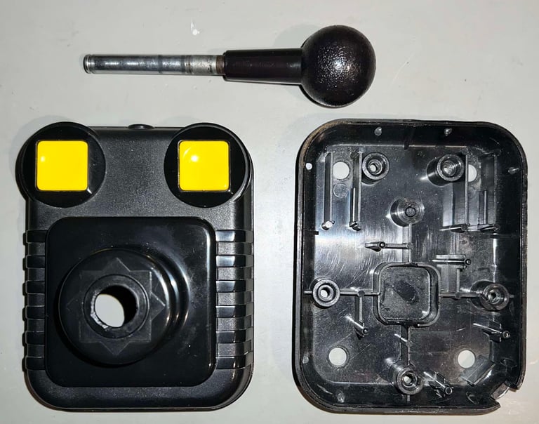

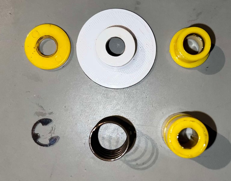

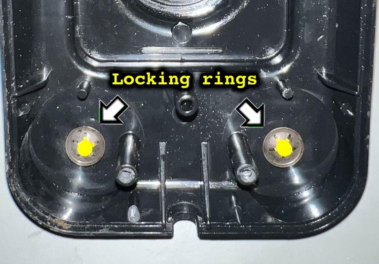
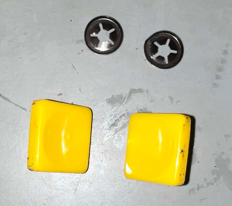
The two locking rings holding the FIRE buttons in place are really hard to remove on this one. I almost (!) gave up. The metal was really hard to bend, but I made it eventually.


Exterior casing and plastic parts
All the plastic parts, and the metal joystick shaft, are placed in a box filled with mild soap water for about 24 hours. This will dissolve most of the grease from the parts.
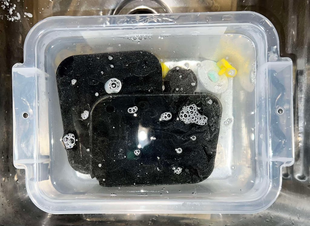

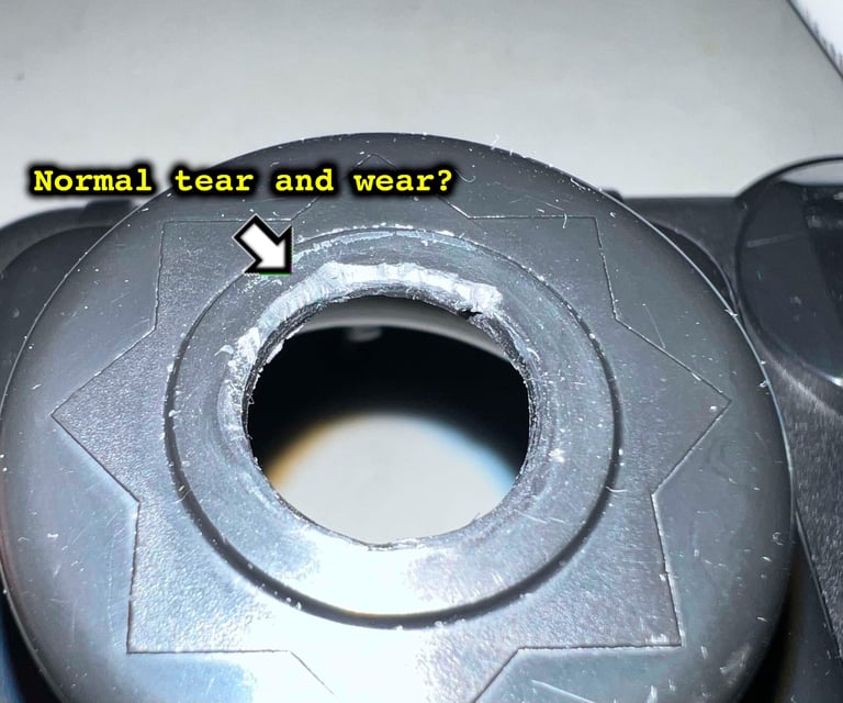
The top- and bottom cover looks very nice after cleaning. But I notice something interesting on the top cover: there are some marks on the plastic which does not do be caused by normal tear and wear(?). It is almost like it has been used a sharp tool of some kind? Nevertheless, it does not affect the function in any way.
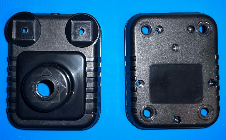


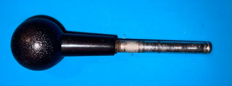
As for the rest of the parts they also look very nice after cleaning. And I can not see any major damage, just the normal tear and wear.


Lubrication
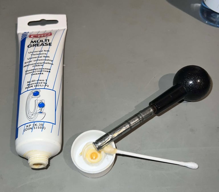
Although not strictly required, it is good practice to add a small amount of grease on the metal shaft and the inner plastic parts. A thin layer of multi-purpose grease is applied with a Q-tip on the parts. This would reduce the level of any squeaky noises and also prevent corrosion.

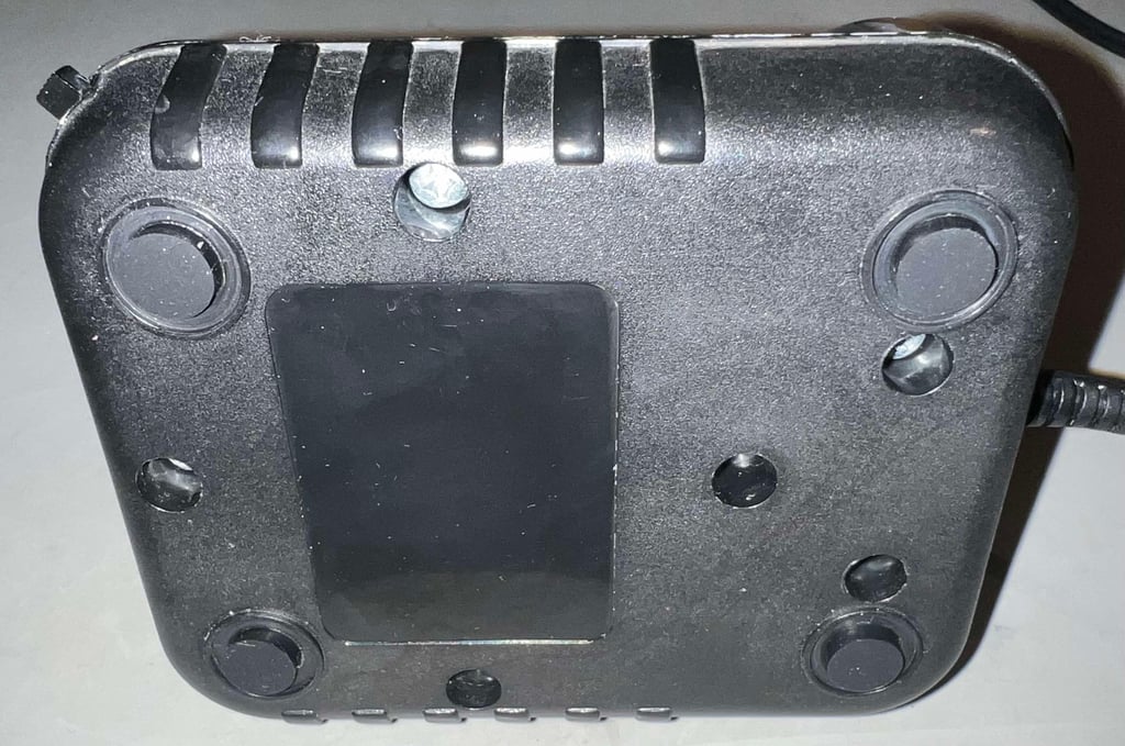
Adding new rubber feet
All of the original rubber suction cups are missing. Instead of replacing with new suction cups, some small 10 x 3 mm rubber feet are added. This will prevent dust from entering the casing, and also make the joystick stick to the table.

Electronics and microswitches
Autofire
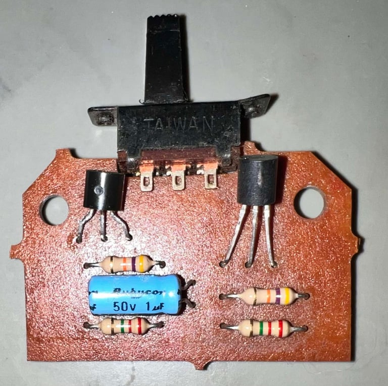
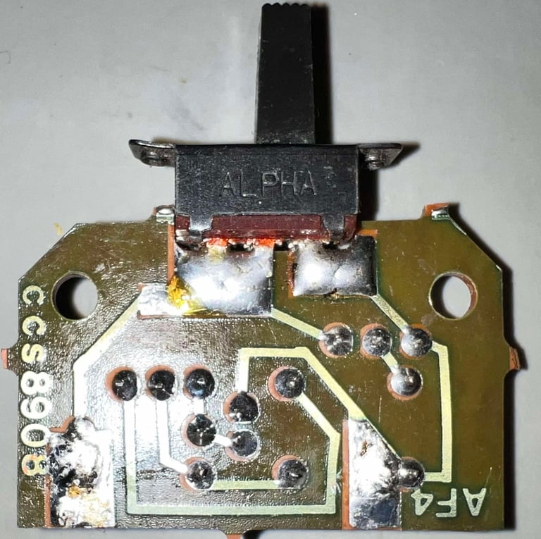
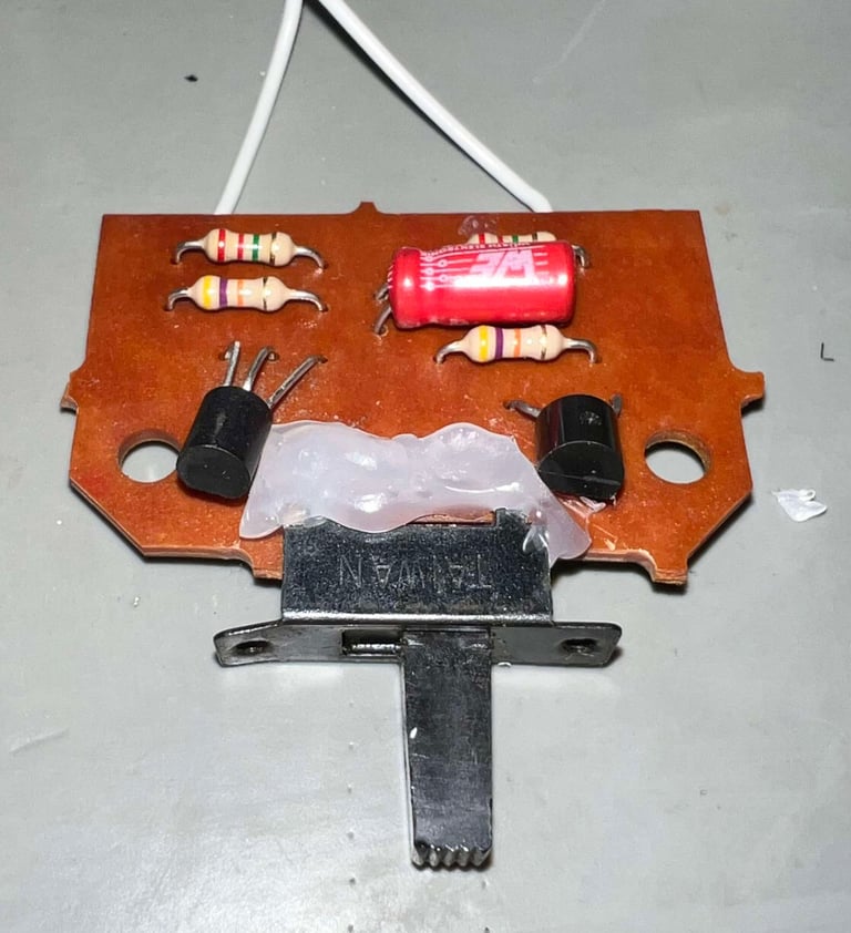
The Zipstik series use a variety of autofire PCBs. They all function (more or less) the same way, but with different components. This one use the "AF4" PCB and is composed of four resistors, two transistors and an electrolytic capacitor. There is some flux residue on the PCB, but otherwise it looks to be in good condition.


Replacing the capacitor and fixing a design flaw (?)
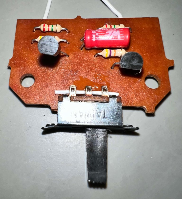
The autofire use a 50 V [1uF] electrolytic capacitors. Since this is old, and can dry out, it is replaced with a brand new. But this PCB also have a design flaw from my point of view. Since the autofire use only half of the toggle switch, only half of it is soldered to the PCB. One side of the switch is basically just floating on the PCB. From an electronic perspective this make totally sense (since it is not used for anything), but from a mechanical perspective this is not good. Since the switch is not properly soldered to the PCB the switch is likely to either disintegrate or be ripped opp the PCB when in use.
So fix the design flaw, a thin isolated wire is placed beneath the three contacts. The wire is fastened with some super glue. With the wire in place, the rest of the switch is fastened to the PCB with a glue gun.
Below is a picture of the PCB with the new electrolytic capacitor, and the wire fix.


Cleaning the microswitches
All of the microswitches are placed in a jar filled with isopropanol for several hours. This will make the isopropanol soak inside the microswitches and dissolve any old grease inside them.
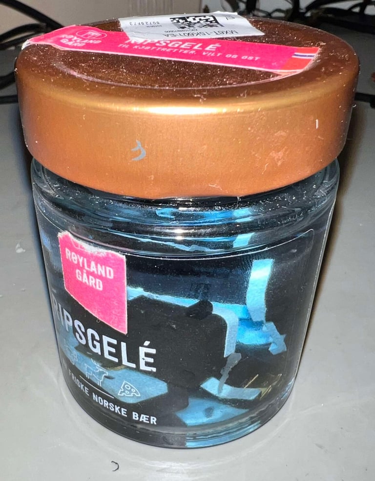

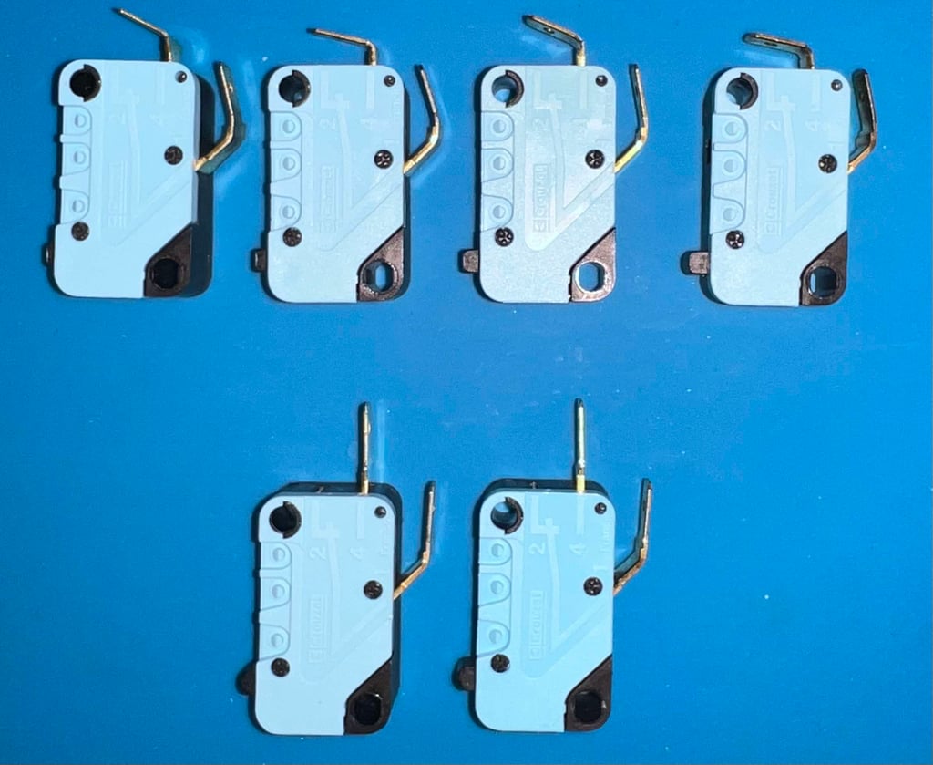
After cleaning the microswitches look as new. Zipstik varies somewhat on the brands used in the joystick. This one use high quality switches from Coruzet.

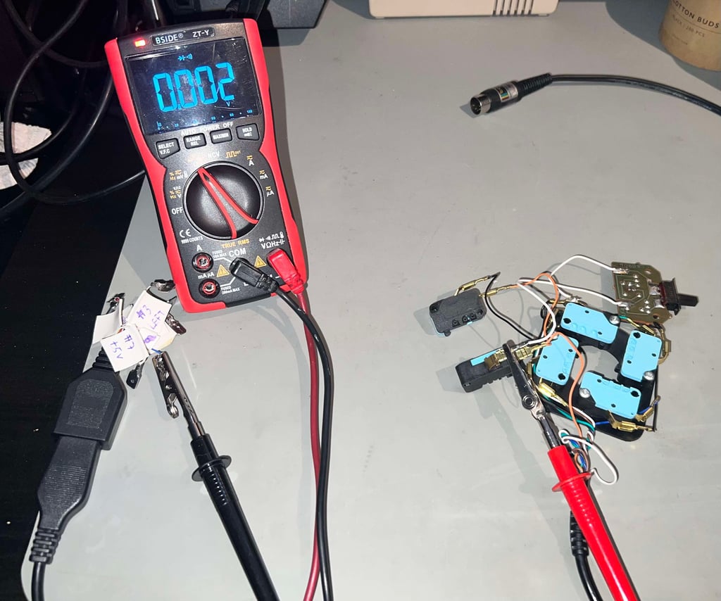
The wire, connector and all the microswitches are tested with a multimeter before assembly. It is good practice to do so as it would reveal any bad wire or connection before everything is re-assembled.

Testing
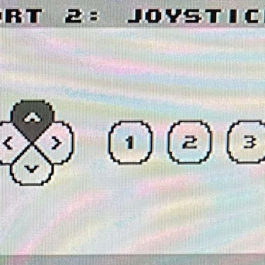
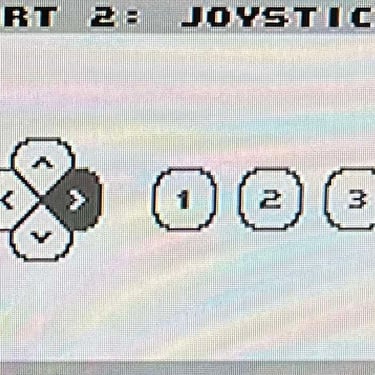
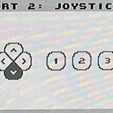
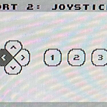
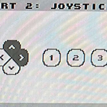
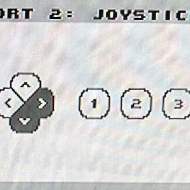
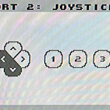
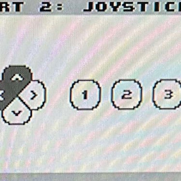
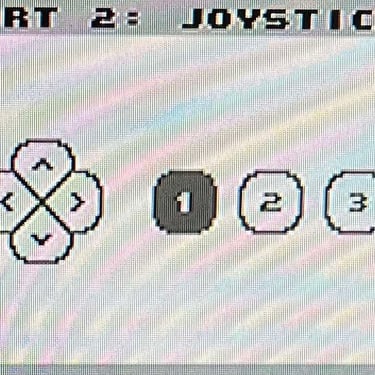
To verify that the joystick work as it should I check it with the Joyride software. Result is that all directions and fire buttons works fine works as expected. All tests pass.
Final result
"A picture worth a thousand words"
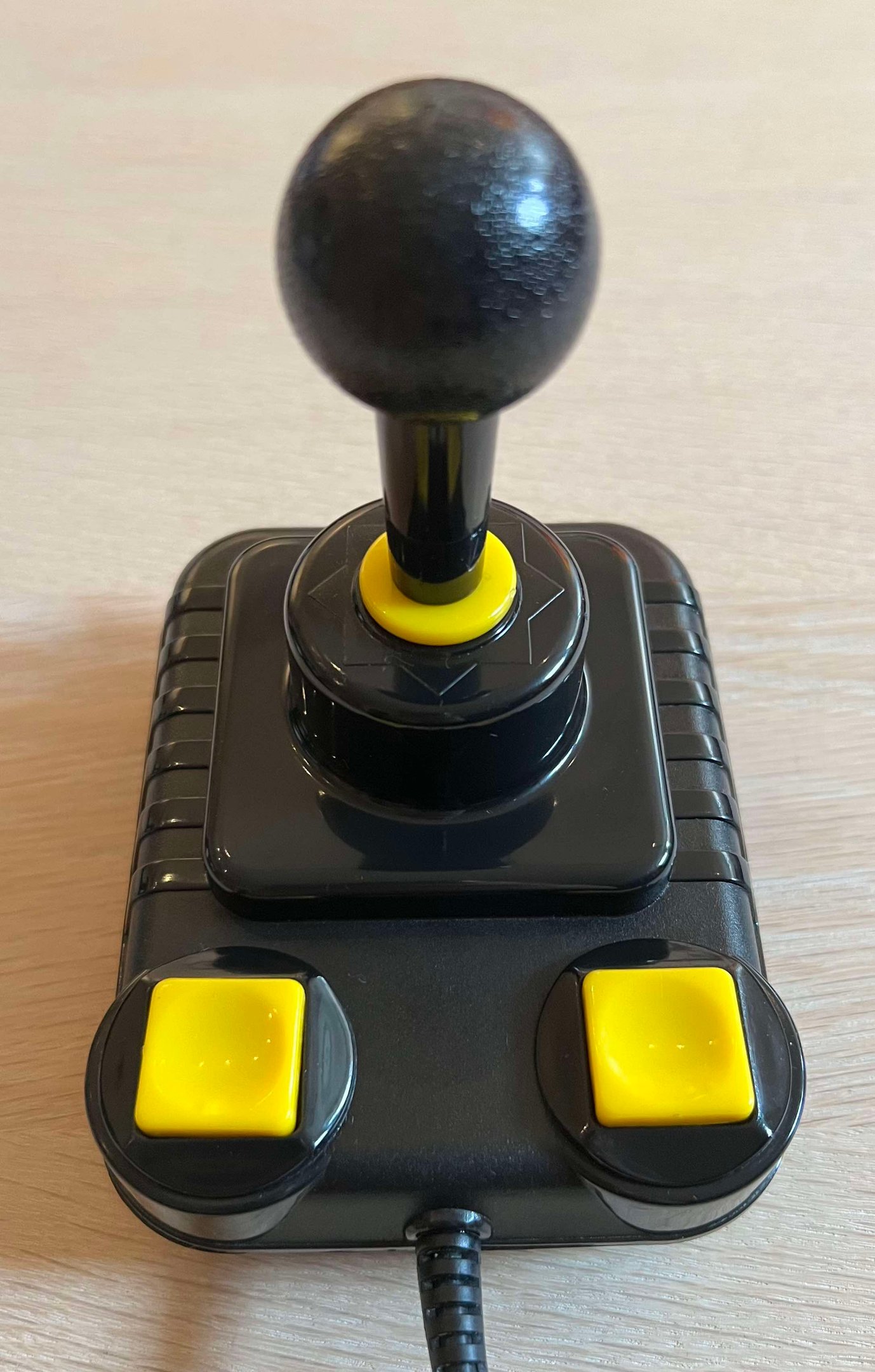
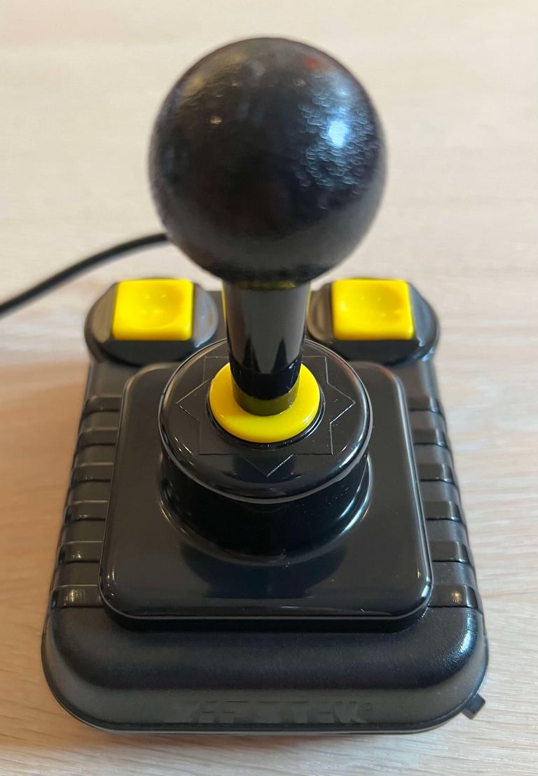
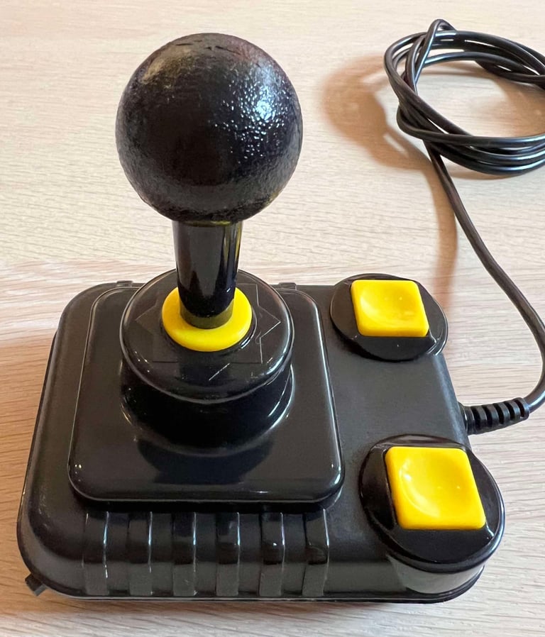
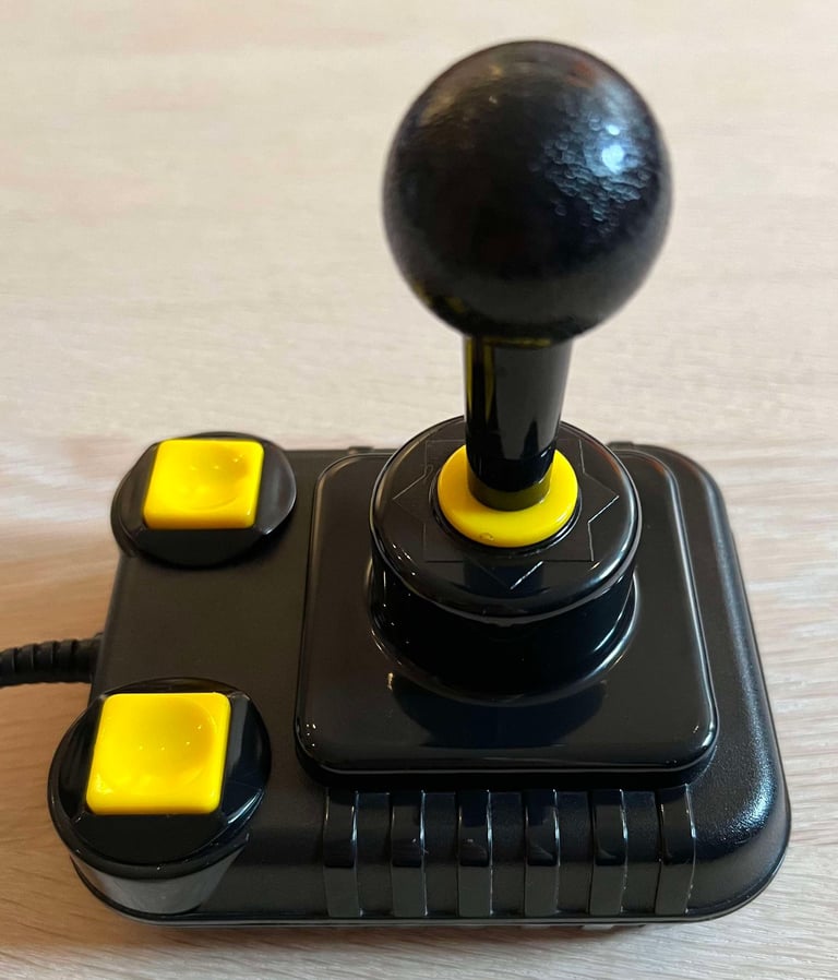
Below is a collection of the final result from the refurbishment of this Zipstik joystick. Hope you like it! Click to enlarge!






Banner picture credits: unknown
