

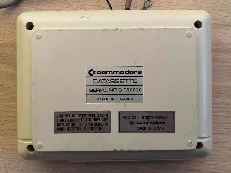
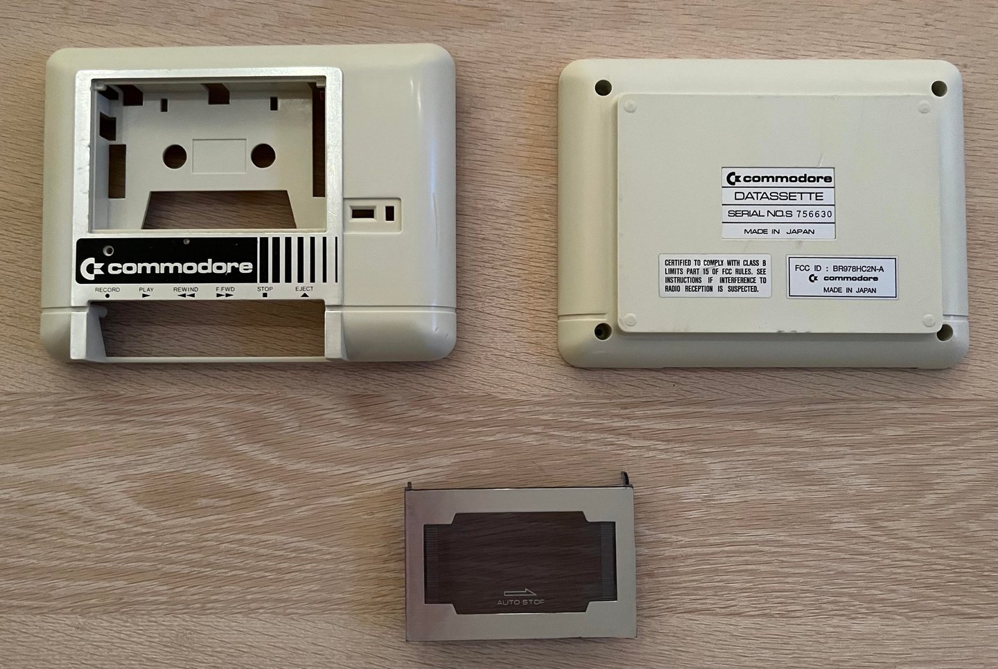
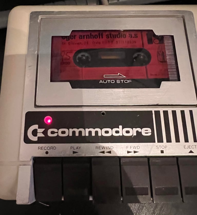
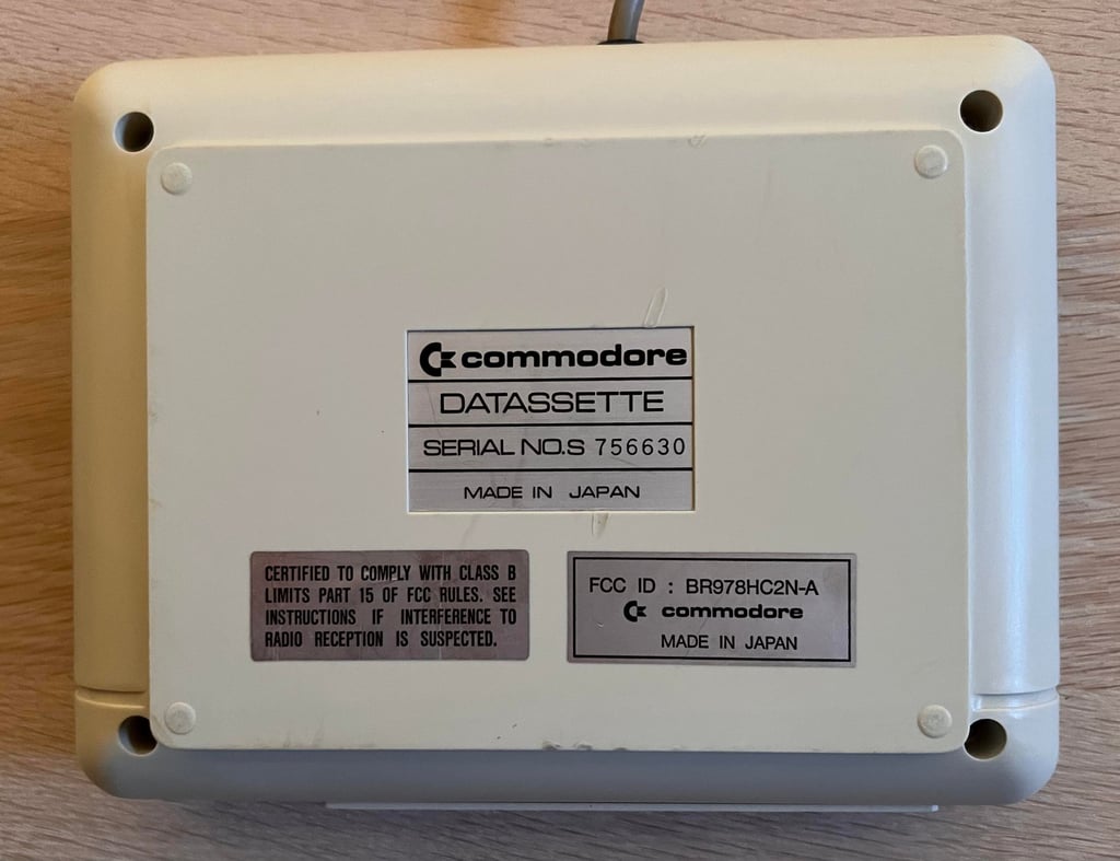
1530 (C2N)
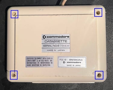
Ser. No. 756630
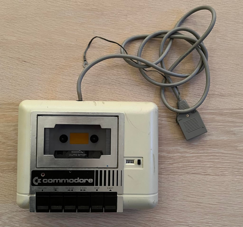
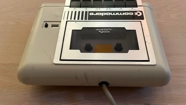
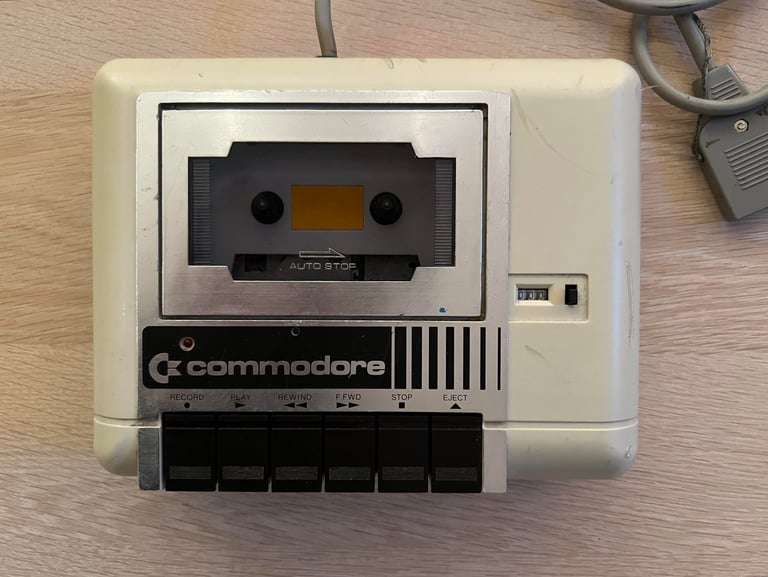
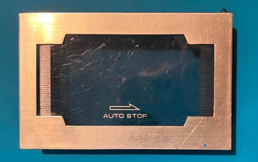
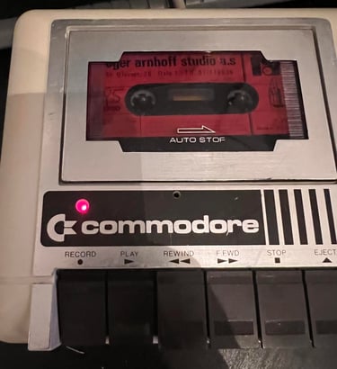
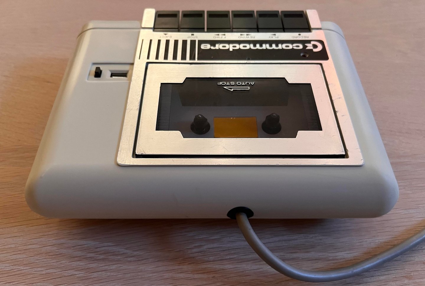
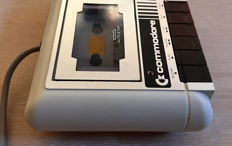
Starting point
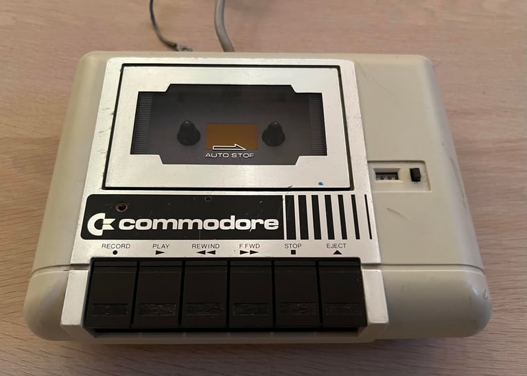
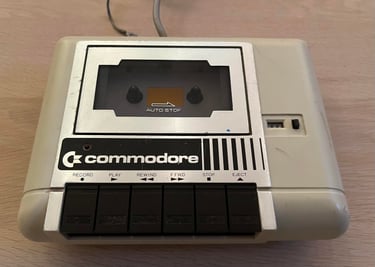
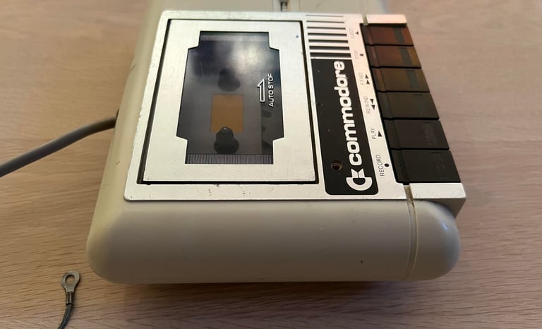
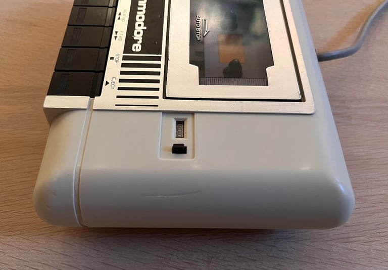
It is easy to see that this is a "Made in Japan" version of the Commodore datasette: the counter is white and behind a small window, and the red LED is placed above the REC button. The datasette seems from the outside to be in OK condition, but it is full of "burn marks". These are not real burn marks, but a result of the cable being twisted around the casing for a long time. I do not know if this datasette works or not at the time of writing.


Refurbishment plan
To refurbish this 1530 datasette the plan is to:
- Clean and remove stains from exterior casing
- Clean the interior mechanics
- Check cable and replace strain relief
- Check PCB for corrosion and replace old electrolytic capacitors
- Replace motor- and counter belts
- Check, and if necessary, adjust R/W head for optimal tape reading
- Check, and if necessary, adjust motor speed for optimal tape reading
- Verify datasette operation by testing
Note that these steps are not necessarily done in the order described above, and several of these steps are done in parallell.
Opening it up...
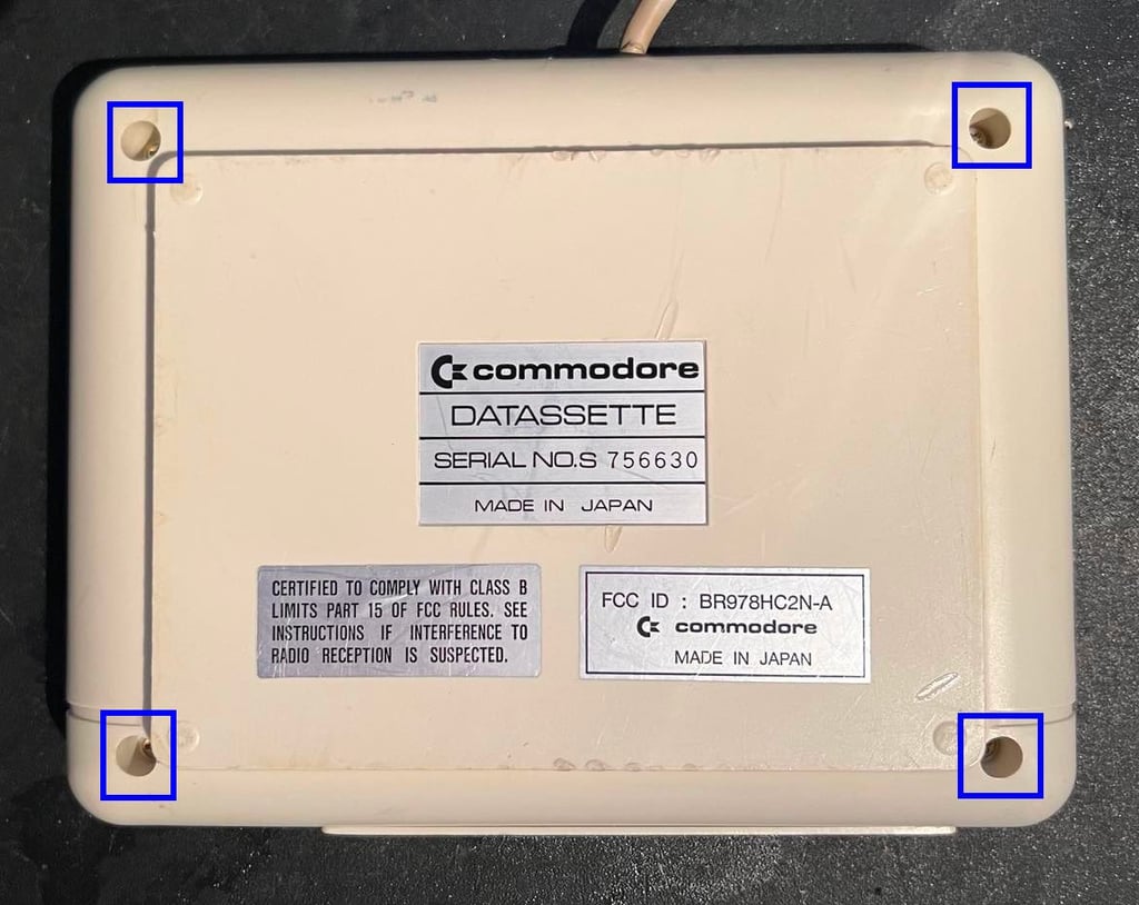
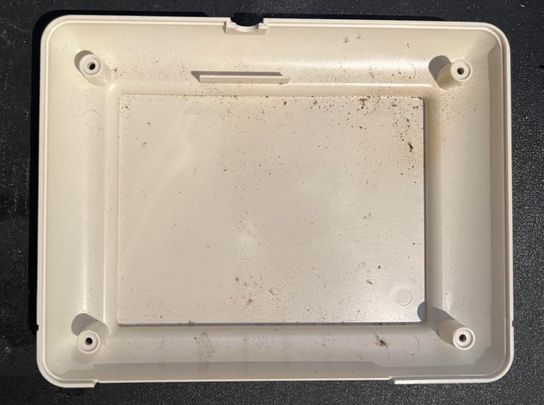
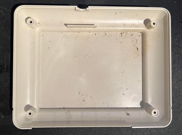
The casing consists of a top- and bottom cover. To separate these covers the fours screws at the bottom are removed.
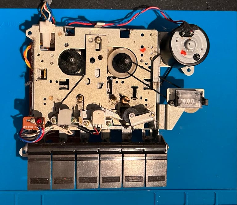
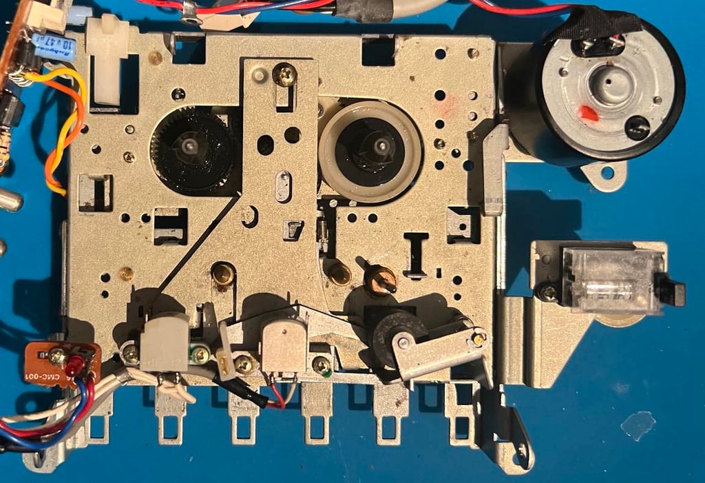
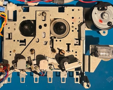
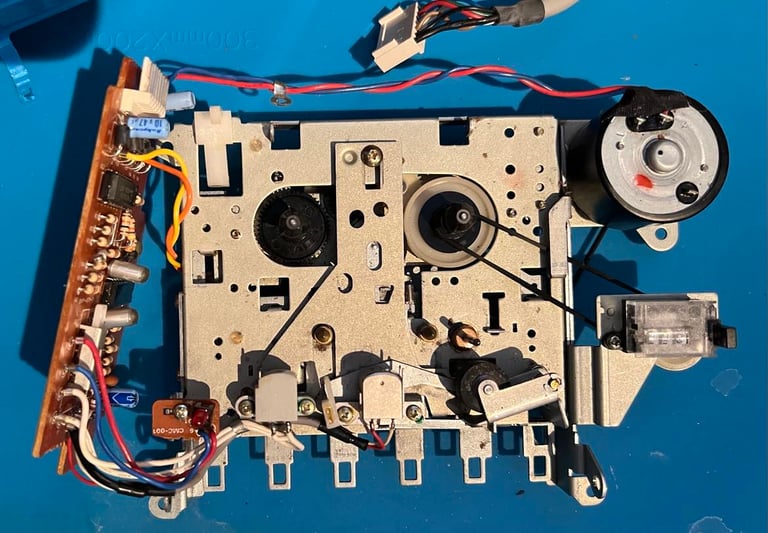
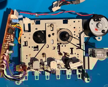
Removing the bottom cover reveals the backside of the interior and parts of the top cover. As can be seen from the pictures below the datasette is very dirty inside. There are dust and grease everywhere. The motor belt is also completely worn out - when turning the flywheel the belt is barely moving - the elasticity is gone. Nevertheless, the interior looks to be intact otherwise.
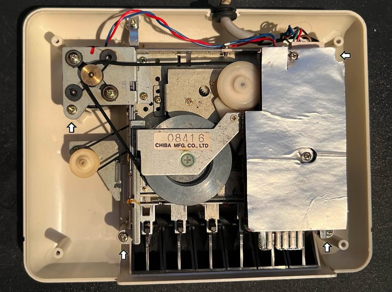
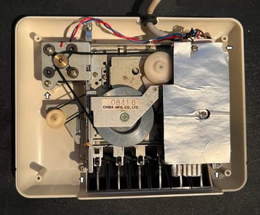
The interior is loosened from the top cover by removing the four screws (see arrows in picture above) and lifted away. This reveals the top cover. It is not very dirty and seems to be intact.
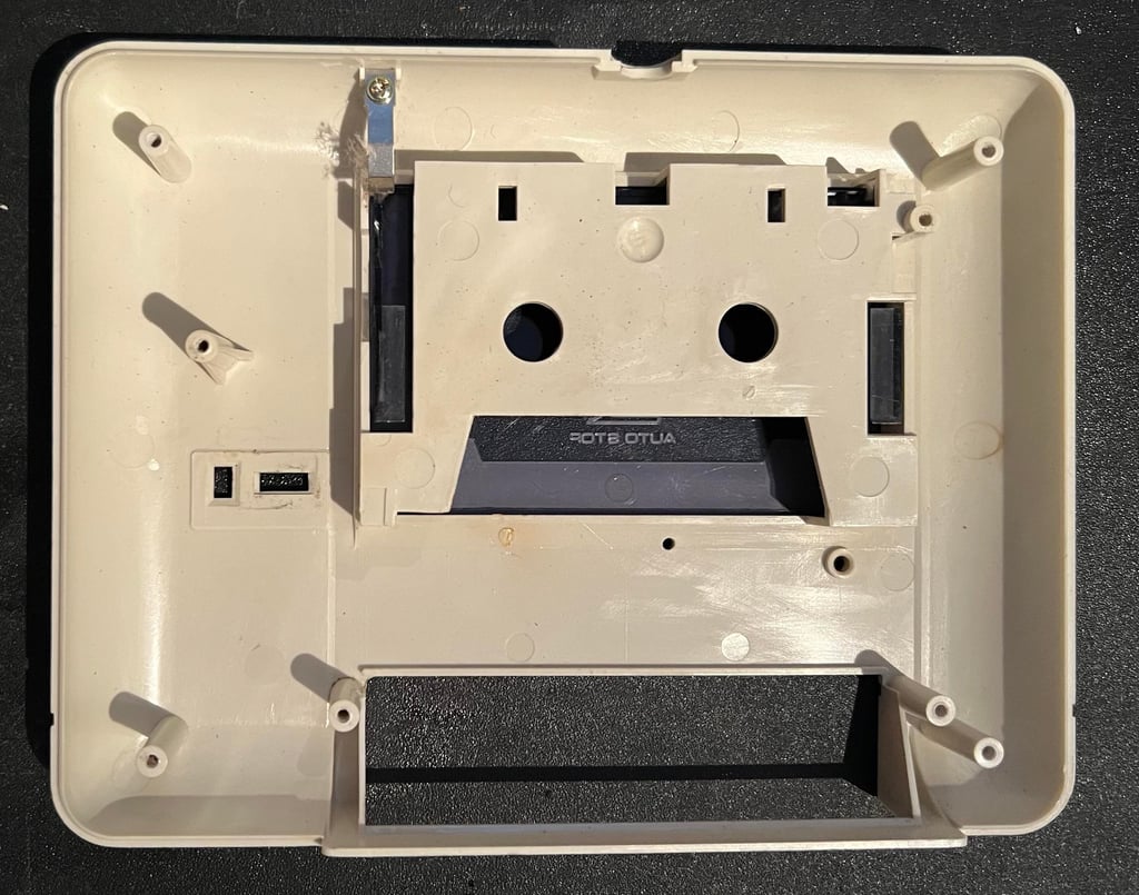

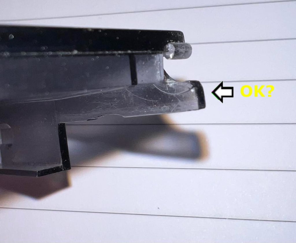
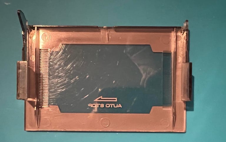
In contrast to the Taiwan version of the datasette there are no need to remove screws to loosen the tape lid. It is just to carefully wiggle it our. But I am not sure if the tape lid is completely intact? It seems to work ok, but I wonder if a part of the plastic hinger is partly broken? Not really sure... it is not completely broken, but maybe a tiny part is missing?


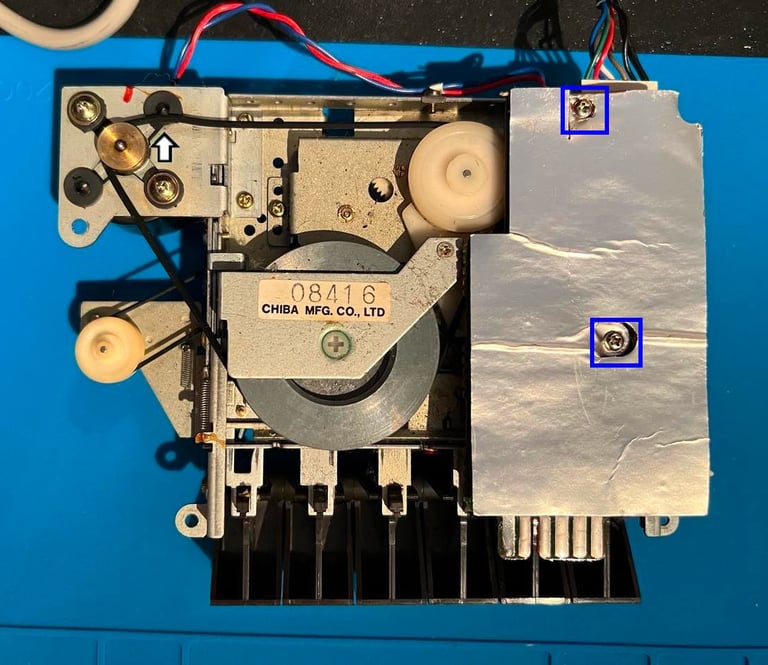
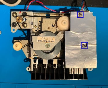
The interior is incredible dirty. It looks to be intact, but there are grease and dust everywhere. And also, the motor belt is completely worn out - no elasticity left. You can even see this from the picture below. Where the arrow point you can see that the belt is "curved" after being stuck in the same position for many years. The to screws (blue squares) are removed and the PCB lifted away.

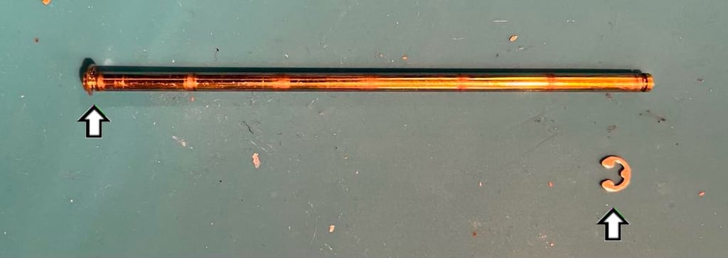
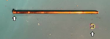
All the six keys are removed to be cleaned. This is done by first removing the E-clip (see picture below) and then pulling the shaft away.
Note that there are two E-clips at the ends of the shaft. But if suffice to remove just one of them.
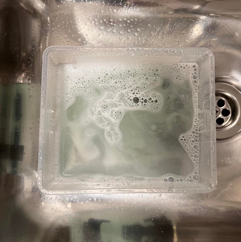
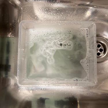
The keys are placed in a box filled with mild soap water and some class cleaning liquid for a few hours.
Exterior casing
The casing is thoroughly cleaned with mild soap water, glass cleaner and isopropanol. This cleaning removes all the grease and dirt, but the "burn marks" are still left. To remove the severe "burn marks" the casing is sanded with P1200 paper for quite a long time. Also, the whole casing is polished with acrylic polish several times.
Not all the marks are gone, but I think the casing now looks way better. By no means, it is not perfect - but compared with the starting point I am very satisfied.

Interior mechanics
The interior looks to be in very good condition except for being full of grease and dirt. Both sides of the interior are cleaned thoroughly with Q-tip and isopropanol. This is a tedious job, but the end result is very good. See pictures below.
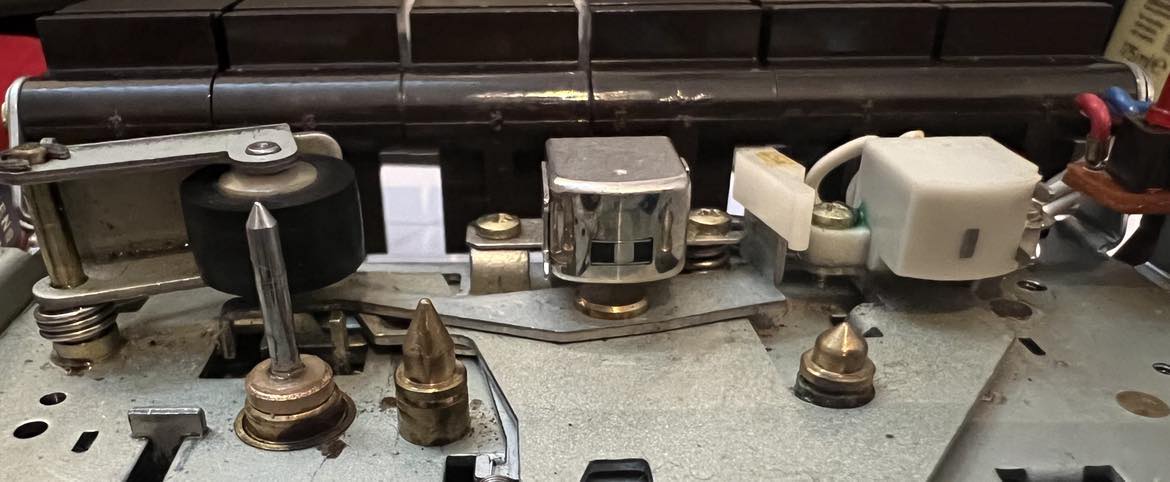
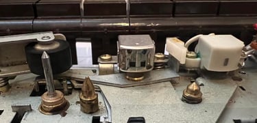
A prerequisite for the datasette to operate without errors is that the read/write head, the erase head and the capstan plus pinch roller are clean. If these are not clean you risk that the datasette will have problems reading/writing signals from/to tape - or that the tape "slips" during playback. All of these important components are cleaned thoroughly with Q-tip and isopropanol. A smart way of cleaning the pinch roller and capstan is to do this while the datasette is connected to the Commodore 64. Below is a picture of the cleaned components, and also some videos on how to clean the capstan and pinch roller (from a different datasette).


Replacing the belts
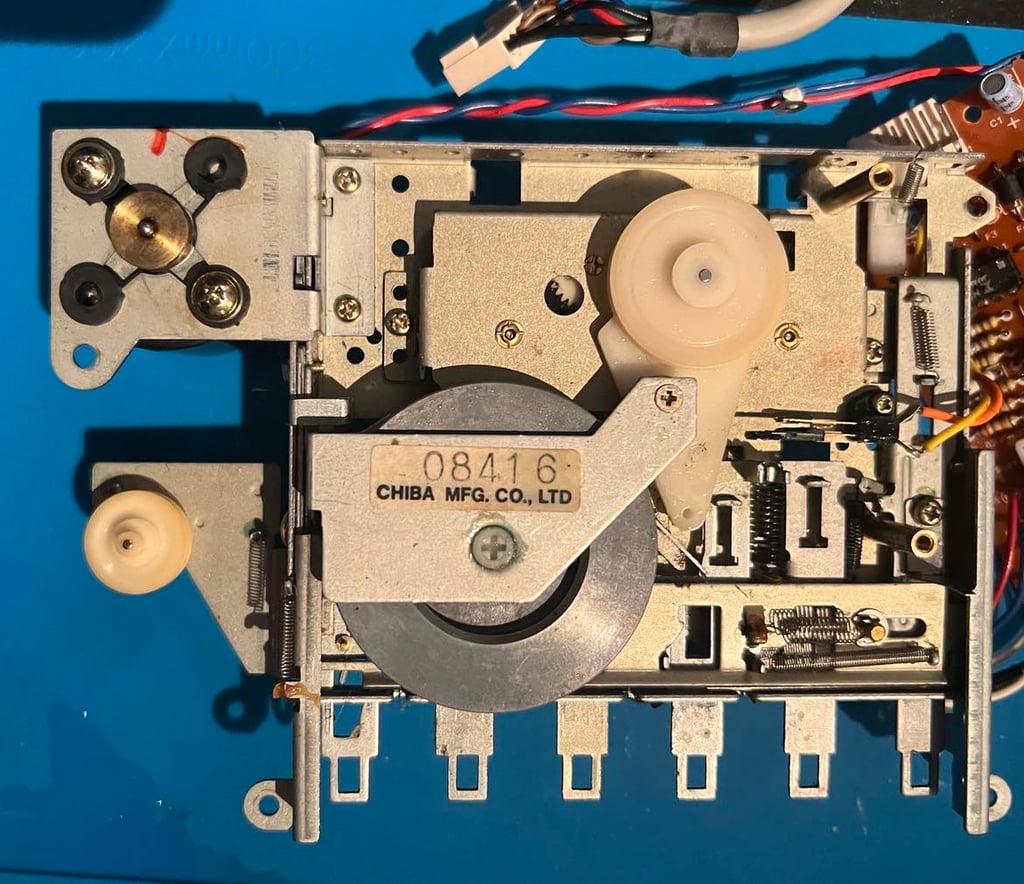
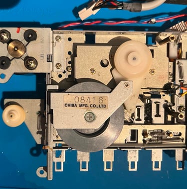
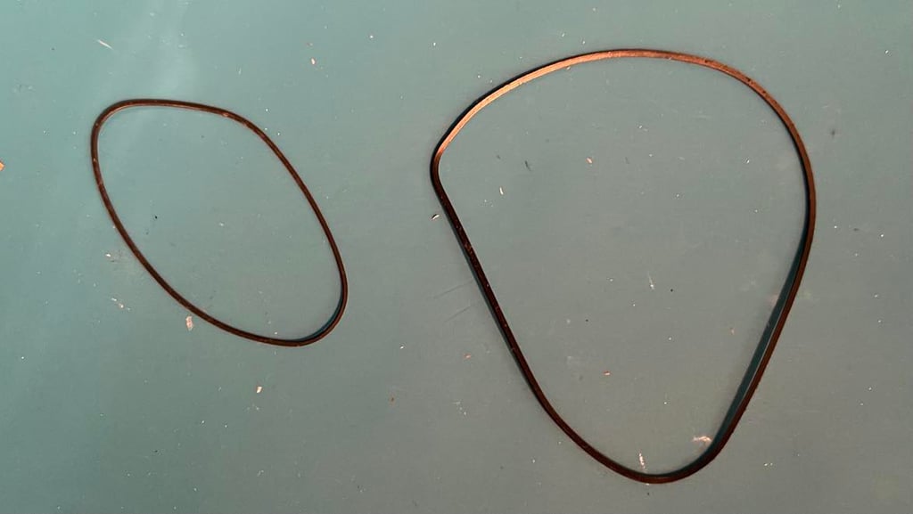
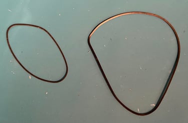
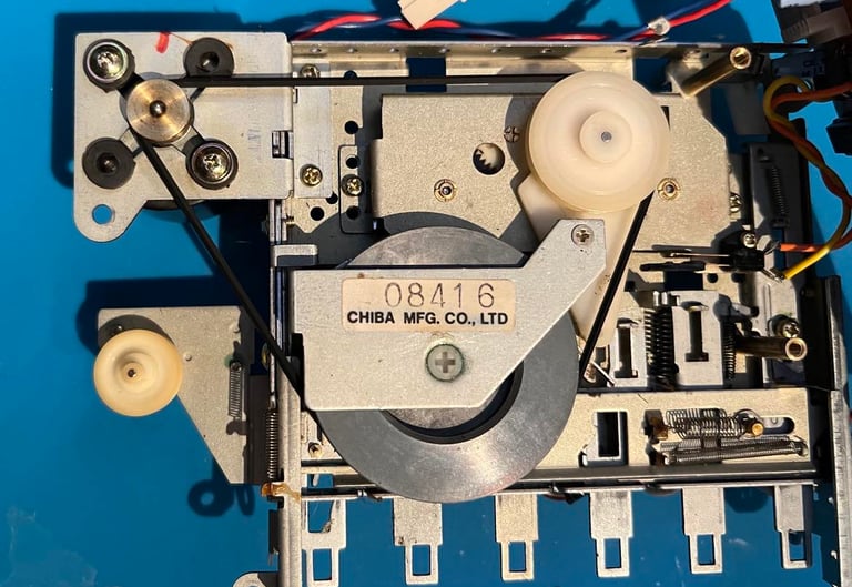
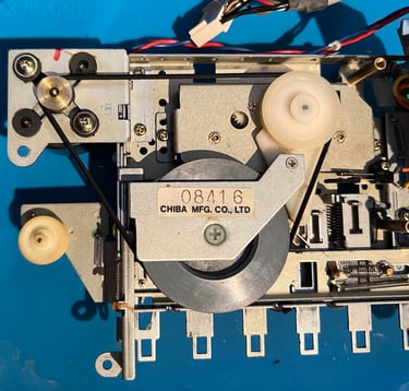
The motor belt is essential for the datasette to operate flawlessly. If this belt is worn out, or damaged in any way, chances are high that the datasette will not work. And as previously mentioned the motor belt is completely worn out in this datasette. It is also good practice to replace the counter belt, but it is not crucial for operation. So I will replace both of these belts. Removing these belts are very easy in the "Made in Japan" version of the datasette - no screws needs to be removed. The motor belt is just lifted straight off the flywheel(s) and the counter belt is removed by carefully lifting the small metal clamp. See pictures below.
A good way of checking the elasticity of the belts is to see if they form natural oval shapes. As can be seen from the picture below the belts are very deformed -> poor elasticity.
New belts from DataServe-Retro are inserted into the datasette. Note that these belts are the "Japanese" version since they differ in since compared to the "Taiwan" version.
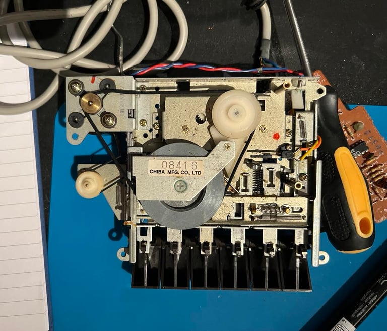
PCB and electrolytic capacitors
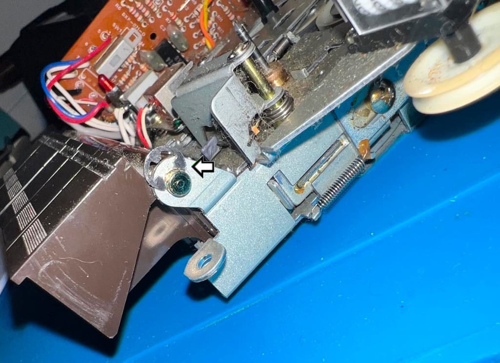
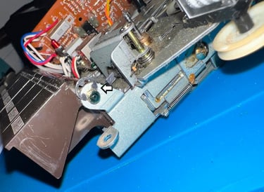
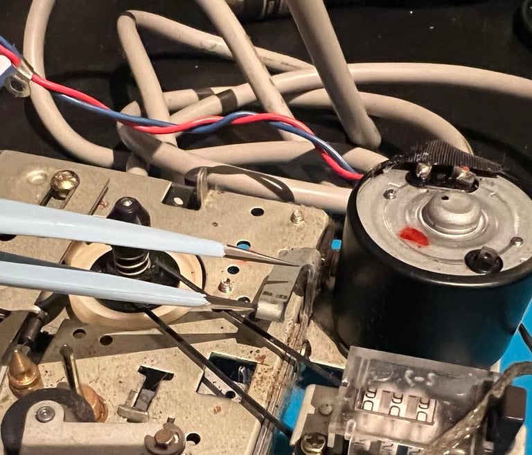
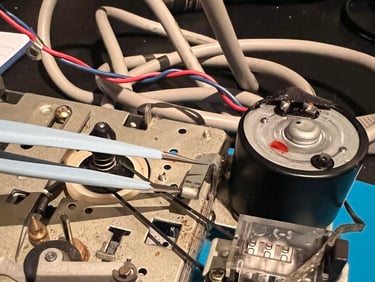
Before the electrolytic capacitors are replaced the PCB needs to be checked and cleaned. To make it easier to do this the cable fastener is removed (one screw - see picture below).
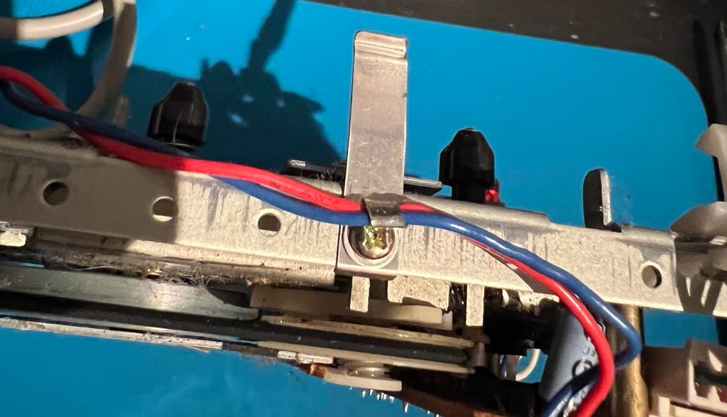
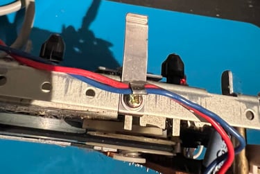
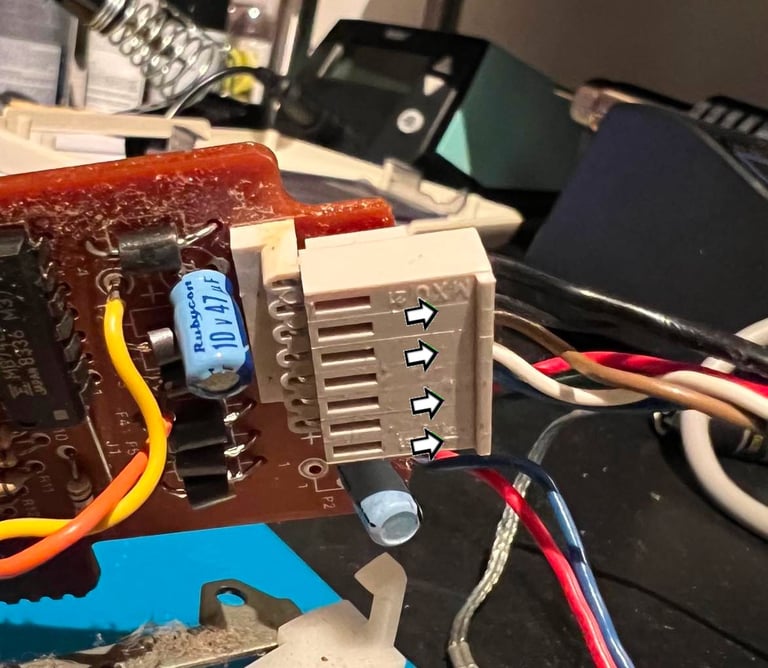
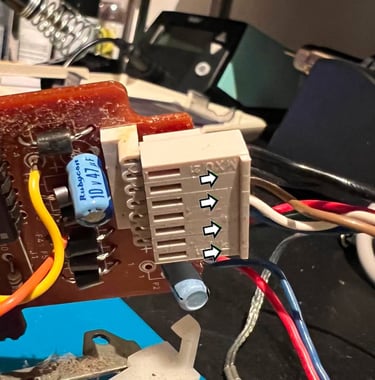
At the end of PCB there is a connector which is disconnected. This is not strictly required, but it makes cleaning and re-capping much easier. To remove the connector a thin flat screwdriver is used to carefully pry it out. The metal pins on the connector base are cleaned with a glass fibre pen and isopropanol.
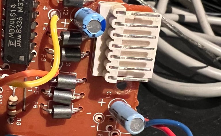
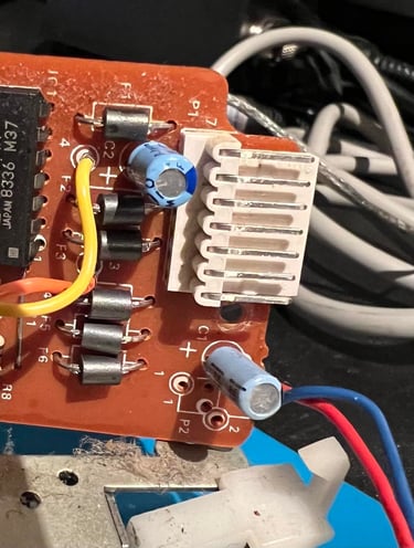
Both sides of the PCB are cleaned thoroughly with isopropanol. And I can not see any damage or corrosion on neither sides of the board.
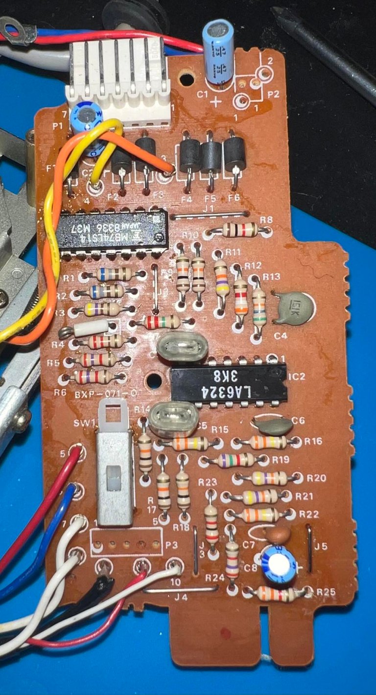
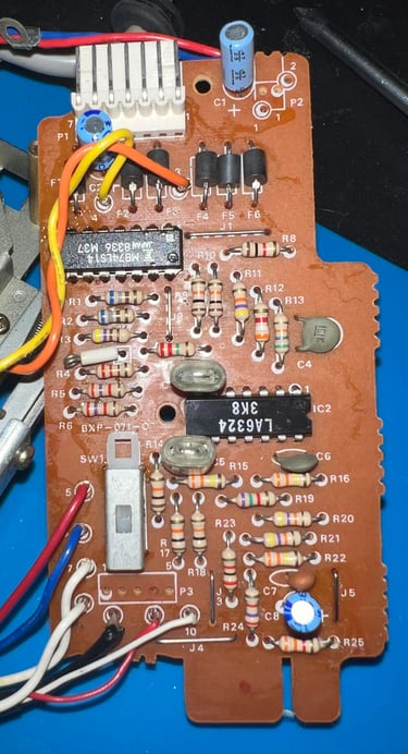
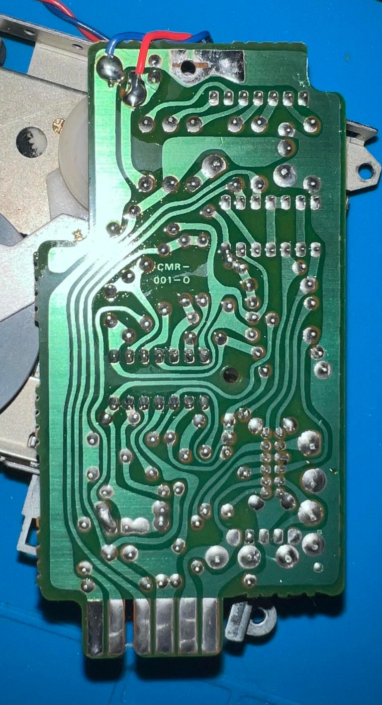

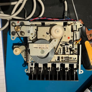
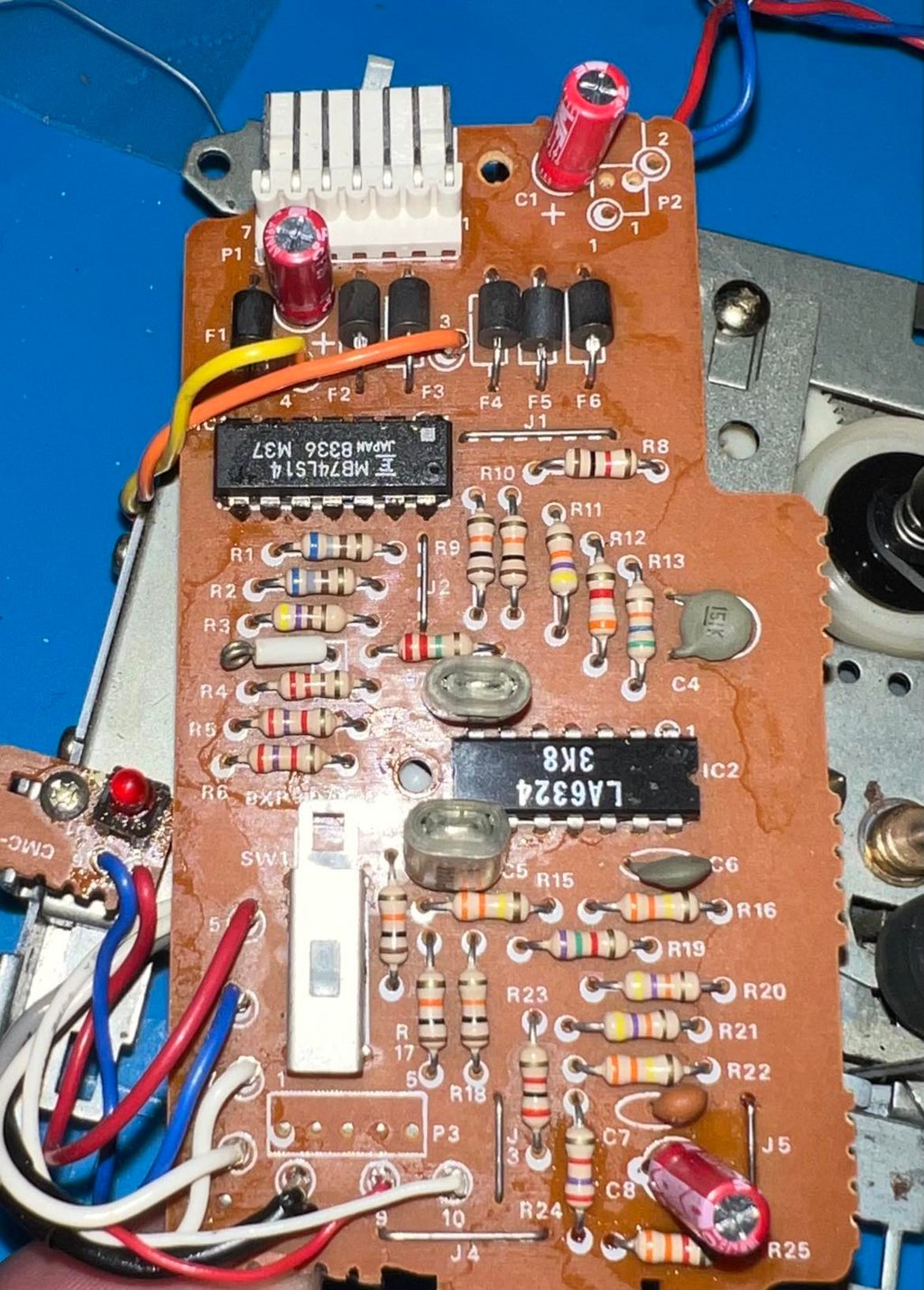
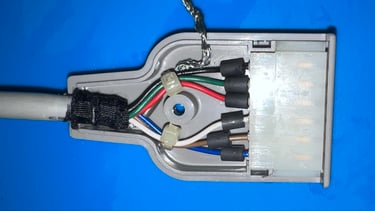
This is a CMR-001-0 version of the PCB. The most interesting things on this board are the LA6324 quad OPAmp and 3 x electrolytic capacitors. I will use the pinout of the LA6324 later when calibrating the azimuth of the read/write head. The three electrolytic capacitors are replaced with new: 1 x 0.47uF [25V] and 2 x 47 [10V]. Note that I used a 50V rating for the 0.47 uF capacitor. This is perfectly fine as long as the voltage rating is higher than what is required. Below is a picture of the PCB with the new electrolytic capacitors.

Cable
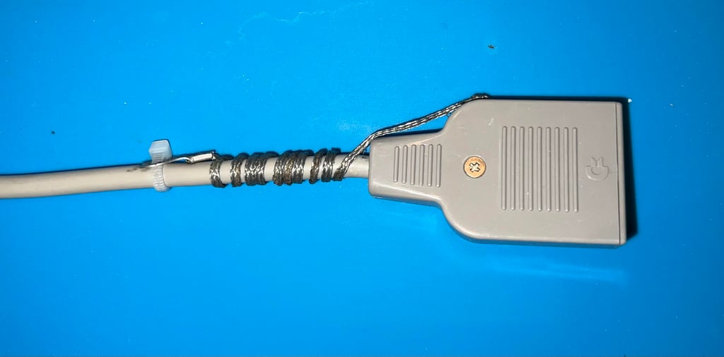
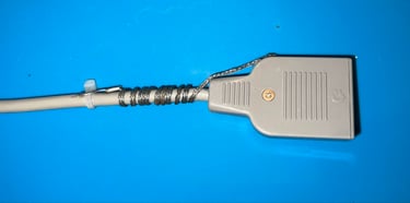
The cable connector housing looks to be undamaged, but full of grease and dirt.
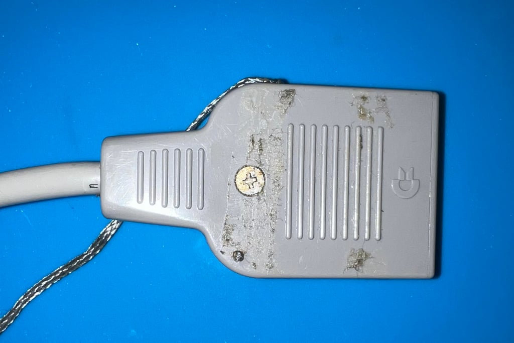
By removing the screw and nut the connector housing is opened. The wires and connector seems to be in good condition - some dirt and grease - but no signs of damage. All of the interior parts are cleaned thoroughly with isopropanol and a Q-tip.

The ground wire is not used on the Commodore 64. This wire is a legacy from the Commodore PET era. It could be cut, but I like to keep it -so the wire is twisted around the cable. Note that if you don´t keep this ground wire out of the way you risk that the wire short circuit the USER PORT(!).
R/W head alignment
In addition to replacing the belts it is crucial to check the read/write (R/W) head alignment and if necessary adjust it. Otherwise the datasette can´t load our beloved tapes without the notorious "?LOAD ERROR" or simply just fails loading.
A detailed article about how I align the R/W head can be found here. As seen in this article I use both an oscilloscope and C64 software to do this operation in two stages; in the first stage I solder on two wires after the 2nd OP-AMP stage, connect the oscilloscope to these wires and then adjust the R/W head until I find the maximum amplitude on the oscilloscope. Second stage I use cassette-azimuth software running on a Commodore 64 while loading games from tape. In this second stage I do not do any adjustments - I only validate that the adjustment done in the first stage is correct.
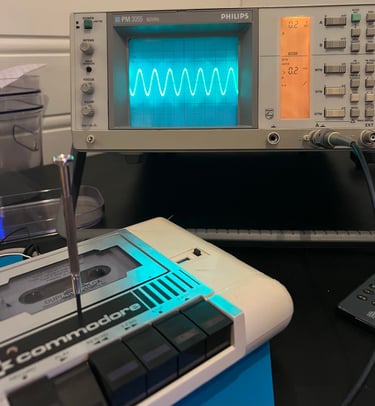
Stage 1 - Aligning the R/W head with the oscilloscope
The oscilloscope is connected to the two wires soldered to the PCB as shown in the article. It is very important that the datasette is completely assembled when connecting the oscilloscope and doing the alignment - with the tape lid and all four screws. If the datasette is aligned with the tape lid removed there is a significant risk that the R/W will be "misaligned" when the datasette is completely assembled. The datasette is loaded with the "Audio calibration tape" and, while running, the R/W head is adjusted with a small screw driver until maximum amplitude is found. Below is a picture of the R/W head alignment.

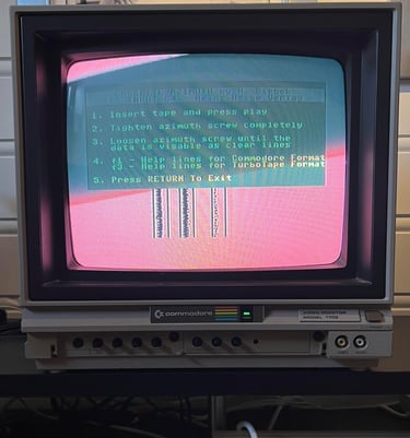
Stage 2 - Verification of the adjustment
To verify the adjustment with a second tool I use the cassette-azimuth software running on a Commodore 64. When the tape is loading there should appear three vertical bars on the screen. And the goal is that these three lines are as "solid" as possible. Note that these lines will never be completely solid, but the goal is that they are more or less straight vertical lines. If you have a misaligned R/W these lines will be scattered all over the screen. Note that the picture is not the best. Reason is that I use a CRT screen.
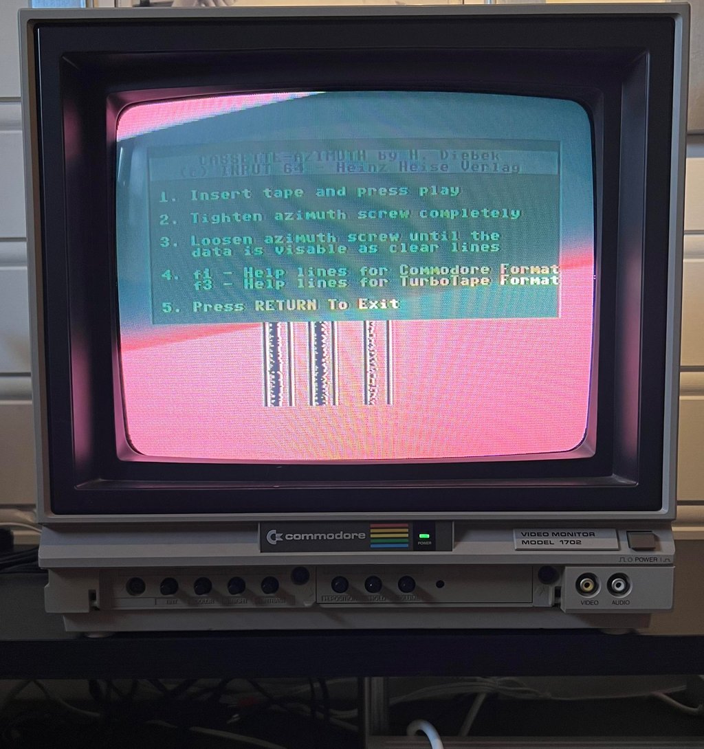
A small video clip from the alignment process is shown below.

To make sure that the R/W head does not move during operation the screw is "locked" in place with some nail polished (kindly borrowed from my daughter).


Calibrating tape speed
Lately I have begun to check the speed of the tape playback. I am still a newbie in this area, but I think there is value in checking the playback speed. Last time I tried this I checked (and adjusted) the speed of the 1530 datasette with Ser. No. 2482981.
The idea is smart, but simple:
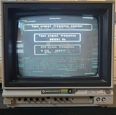
A professional Speed Calibration Audio cassette which contains a 3150 Hz sinewave recording is loaded in the datasette. During playback of this tape a software (developed by J. Deorgee) reads the registered frequency on a Commodore 64. The idea is to adjust the speed until the recorded frequency, 3150 Hz, is measured.
Note that this great idea is not mine. The idea is based on a magnificent article by Jan Derogee and his Tape Frequency Counter software.
So far my experience is that even if the tape produce a sinewave with 3150 Hz the registered frequency count is about 3250 Hz - when the tape speed is correct. Why? I really don´t know (yet). But as the picture below shows the registered frequency is about 3231 Hz so I think this is correct. I will let the testing be the judge.

Testing
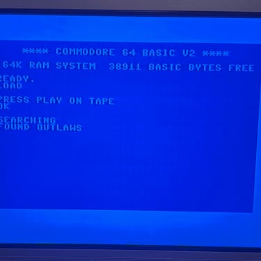
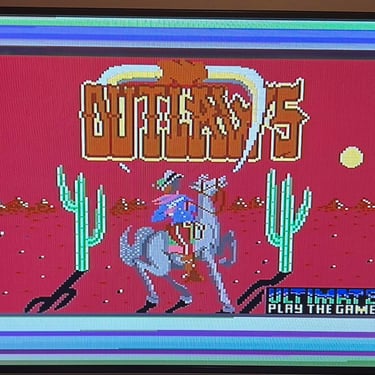
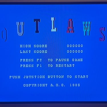
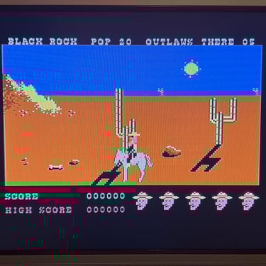
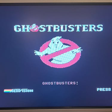
Playback
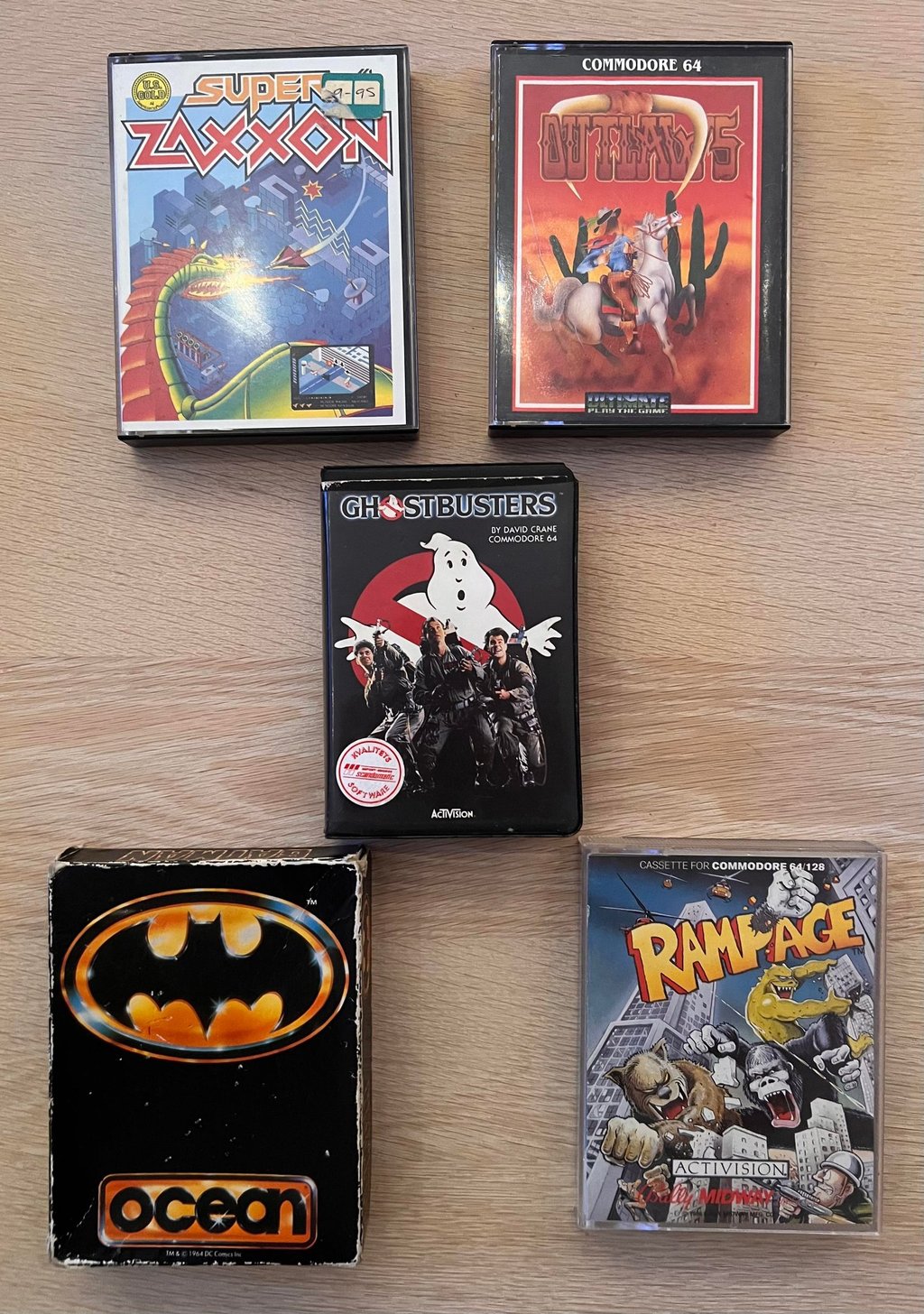
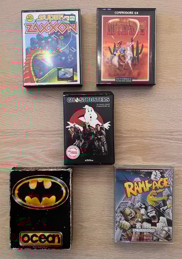
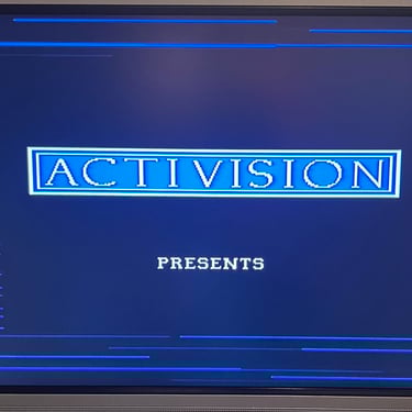
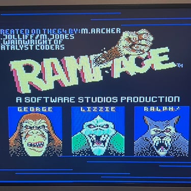
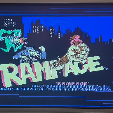
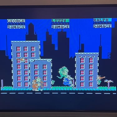
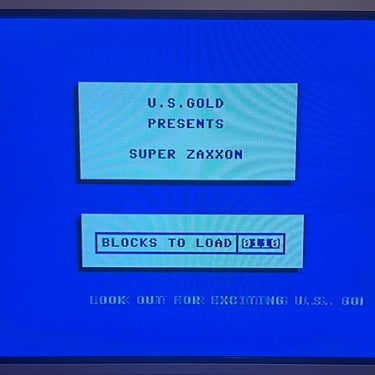
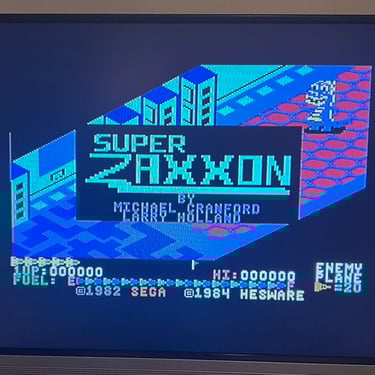
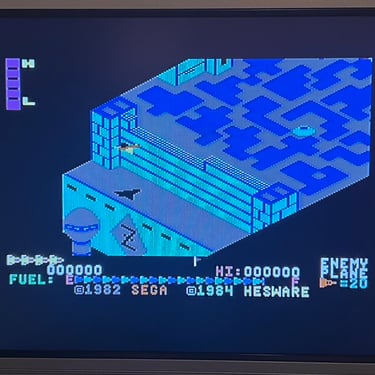
To make sure now works as it should I select five original C64 games to be used for testing. Even if these games are old and worn the load without any problems at all. Below is a picture gallery from the testing.
Recording
The saving functionality is also checked and verified. A small BASIC program is made and the SAVE command is used (and then the program is re-loaded). The LED is also on while recording is in progress.
Testing the tape lid
As previously mentioned there seems to miss a small piece of the tape lid. I can not see that it has any impact on normal datasette operation, but the lid can be lifted out of the datasette without opening the casing. So there is something "wrong", but I do not see this as a major issue.
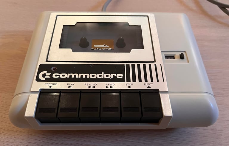
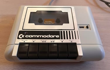
Final result
"A picture worth a thousand words"
Below is a collection of the final result from the refurbishment of this datasette. Hope you like it! Click to enlarge!


Banner picture credits: Evan-Amos