
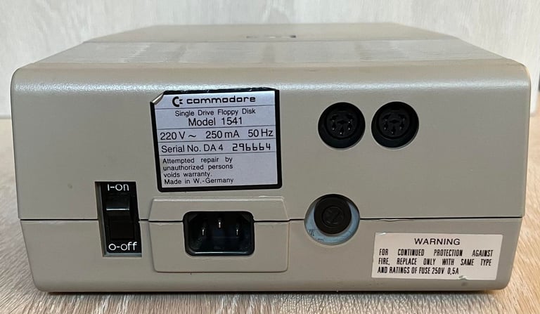
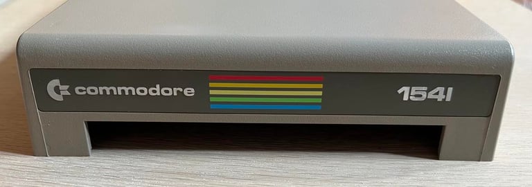
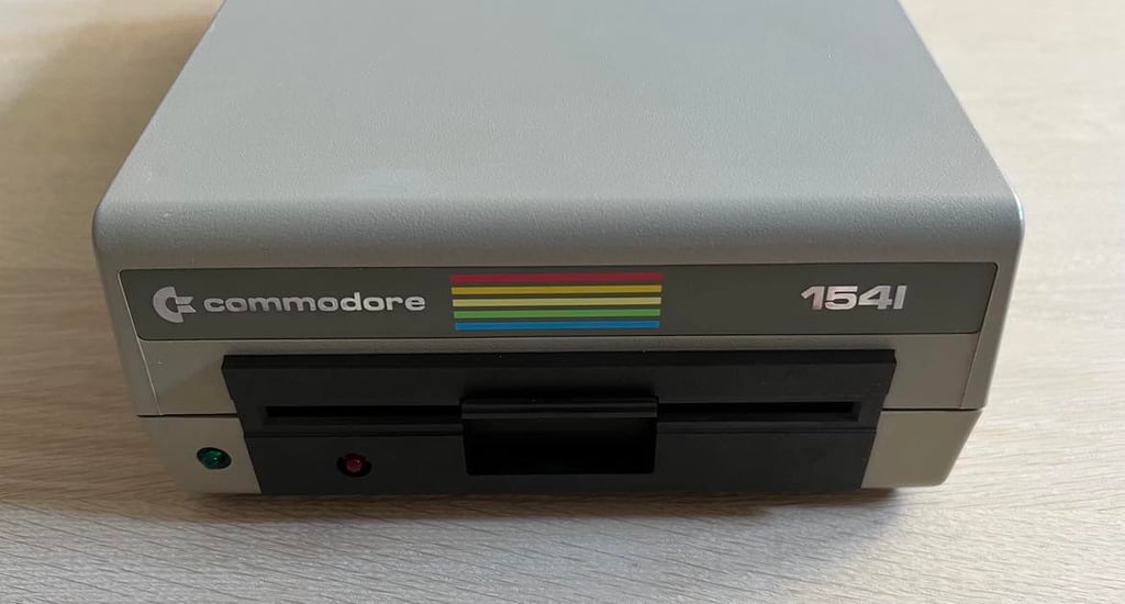
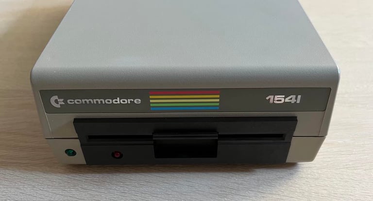
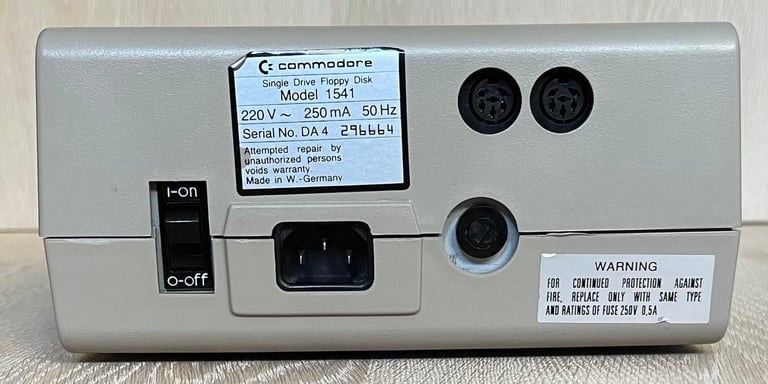
Commodore 1541
Ser. No. 296664
Assy 250442
PCB No 251830 (REV A)
ALPS-Drive
Starting point
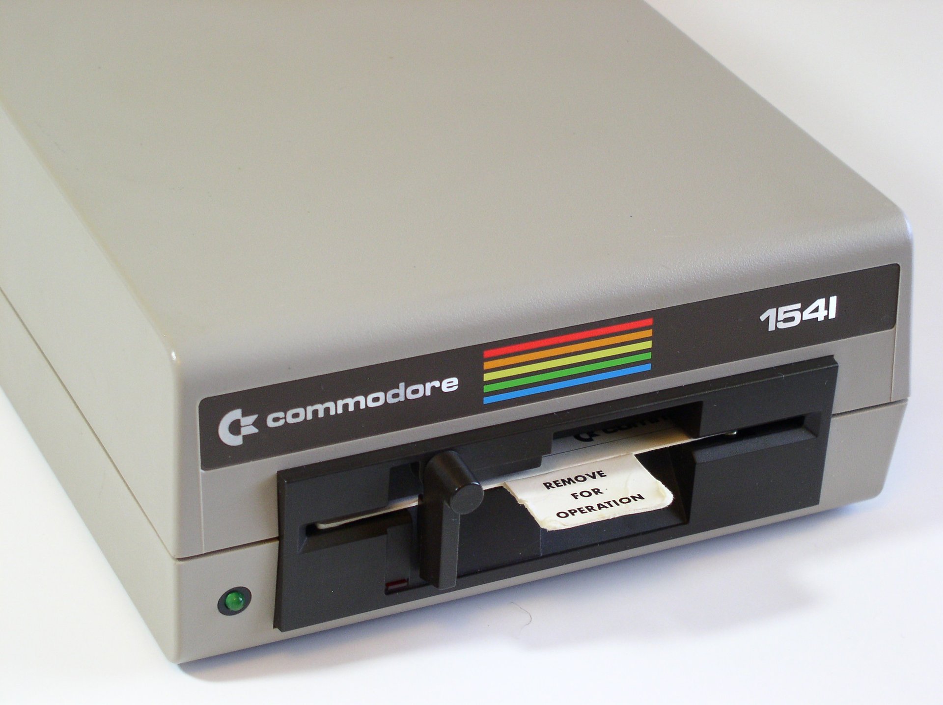
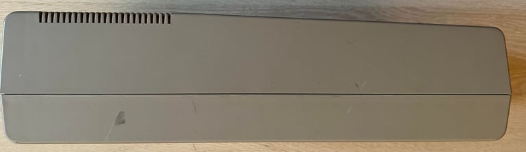
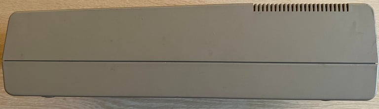
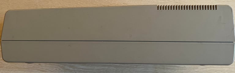
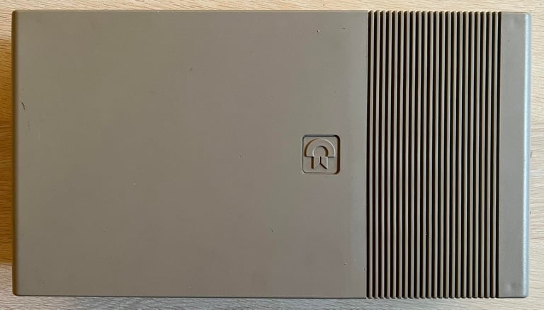
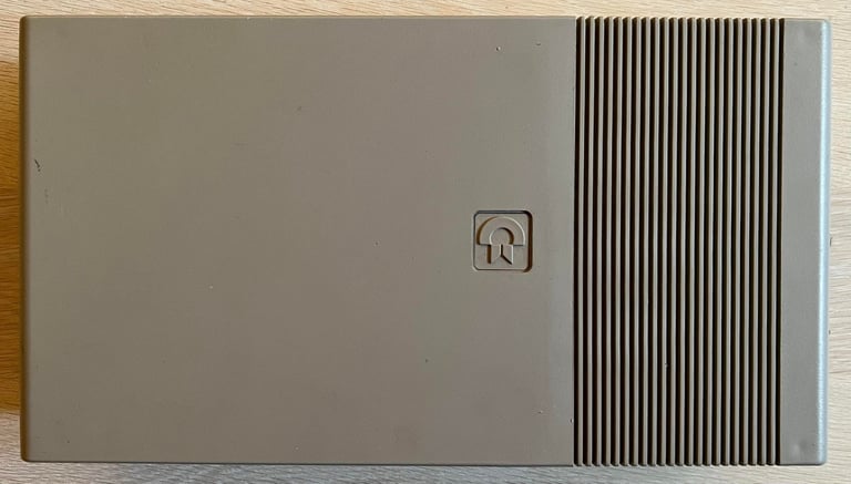
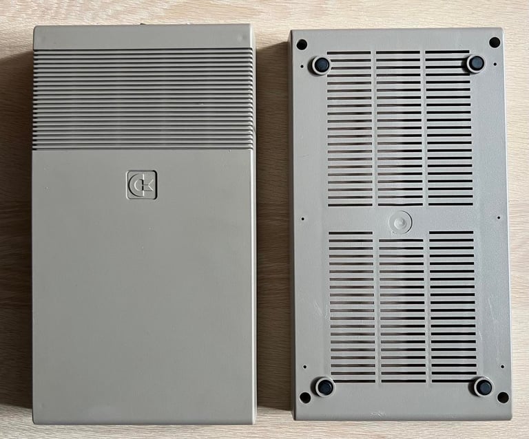
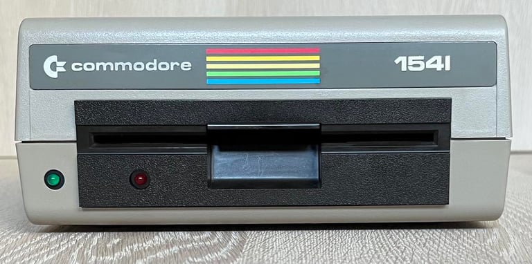
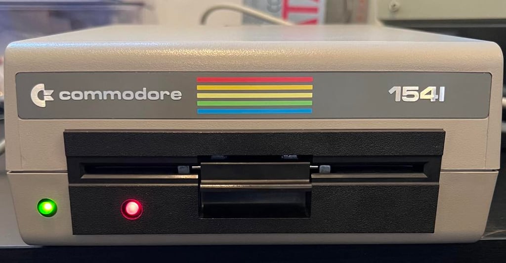
This 1541 floppy drive came to me as "non working" so I already know that some repair will be required. How much? I have no idea at the time of writing. But from the outside this drive looks to be in very good condition. I can not see any significant damage such as cracks or marks. It is slightly yellowed and dirty, but other than that I think this drive looks to have been taken good care of. By seeing the front locking mechanism of this 1541 I can tell this is an ALPS drive.
The badge on the front is partly loose, but nothing I can not fix I guess.


Testing the 1541 for the first time
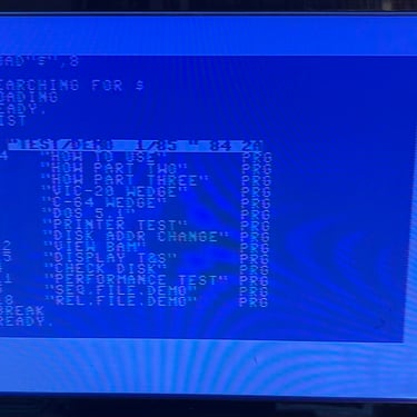
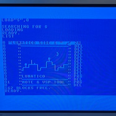
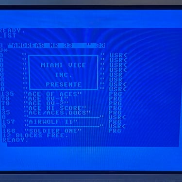
This disk drive is announced to be "non-working", but at the moment I do not yet know what happens when it is used. So I hook it up to a working Commodore 64, insert a known working disk and try the command: LOAD "$",8 to load the directory. The result is that the disk drive get stuck in "SEARCHING" status - no directory is loaded and nothing happens (no errors either).

Refurbishment plan
WARNING: Refurbishing a 1541 will require working on a device connected to live power wire (220 V / 110). Danger! Risk of electrocution!
To refurbish this 1541 disk drive the plan is to do this trough the following actions (some of them in parallell and different order):
STAGE #1: Cleaning, inspection and repairing
- Clean and (retrobright) the exterior casing
- Clean and inspect the PCBs (mainboard and motor unit)
- Repair mainboard
- Clean the interior and lubricate moving parts
- Initial testing
STAGE #2: Replacing old parts and rewiring
- Replace drive belt
- Replace electrolytic capacitors (PCB-motor unit)
- Replace electrolytic capacitors (PCB-mainboard)
- Reconfigure transformer input from 220 V AC to 240 V AC
STAGE #3: Testing
- Verify drive operation by testing the drive with normal Commodore 64 usage


STAGE #1:
Cleaning, inspection and repair
Exterior casing
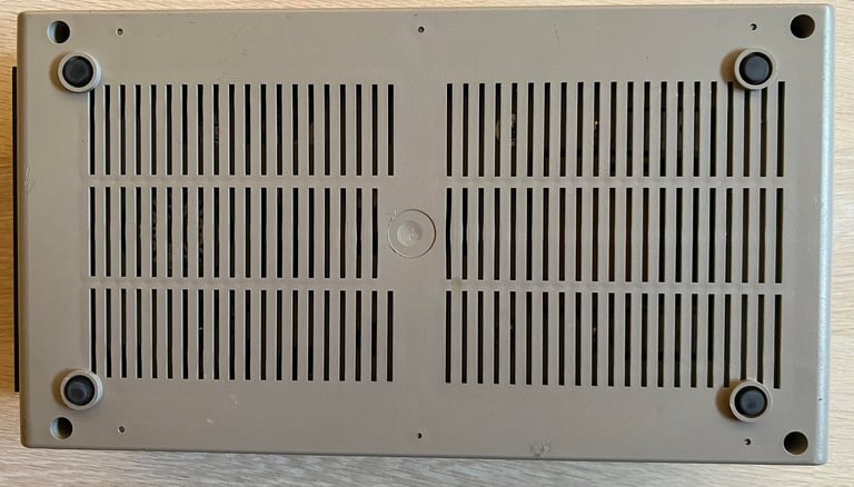
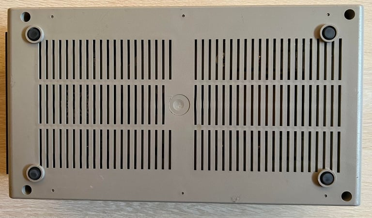
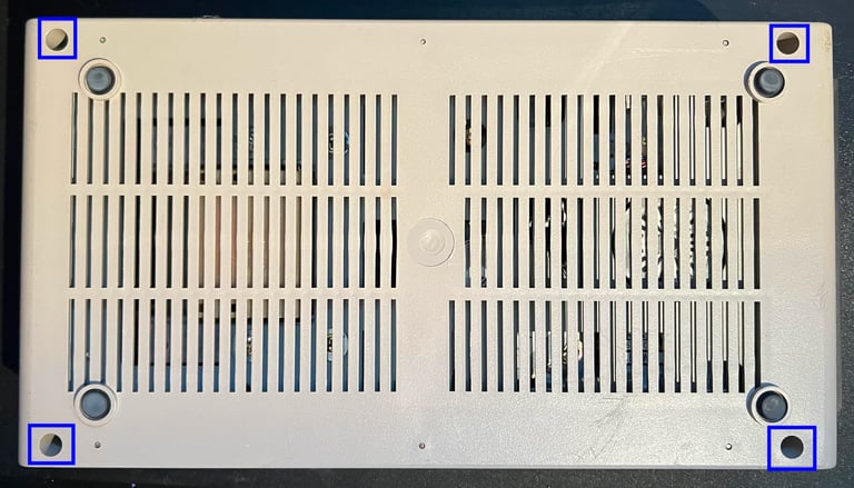
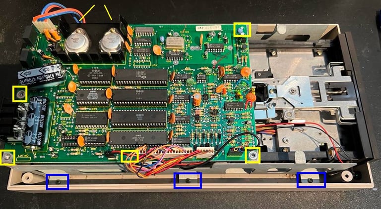
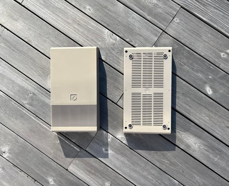
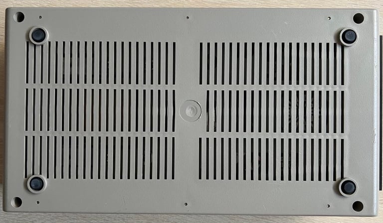
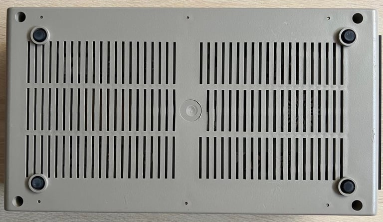
The 1541 casing consists of two main parts; the top- and bottom cover. These are connected by four machine screws which are removed from the bottom side (blue squares).

Then the drive is flipped back to upright position and the top cover is lifted off.

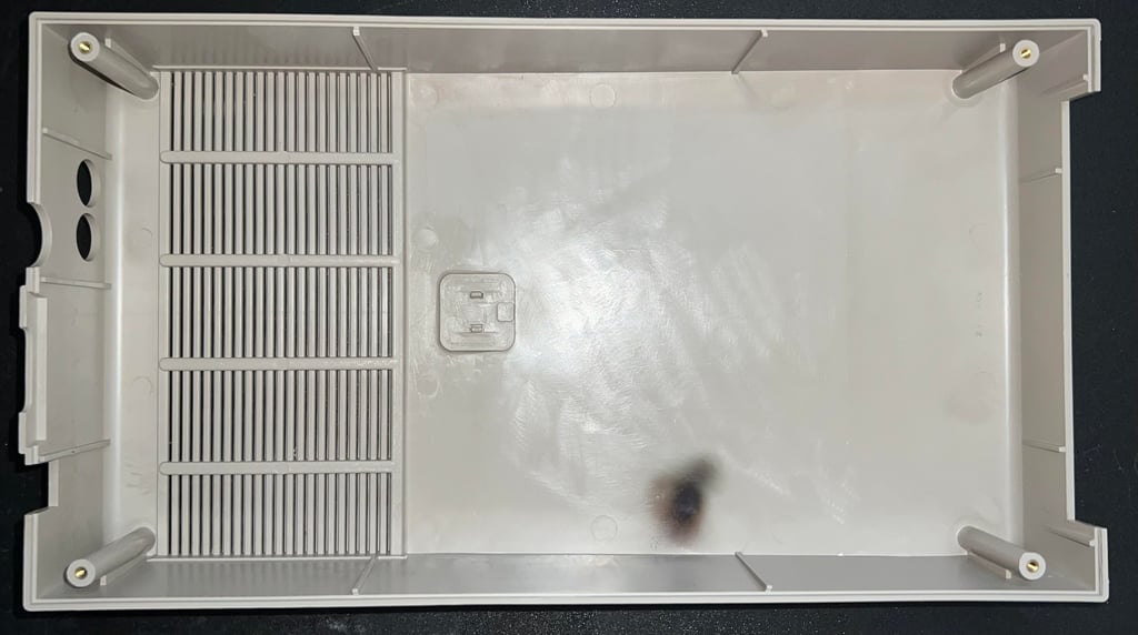
As seen from the pictures there is a dark spot in the top cover - just above the clock circuitry. It looks to me that this is caused by severe heating in that area. Could this also be related to why the drive is not working? I actually do not think so since the 1541 will normally produce a significant amount of heat inside the chassis anyway. But it is definitely worth investigating.
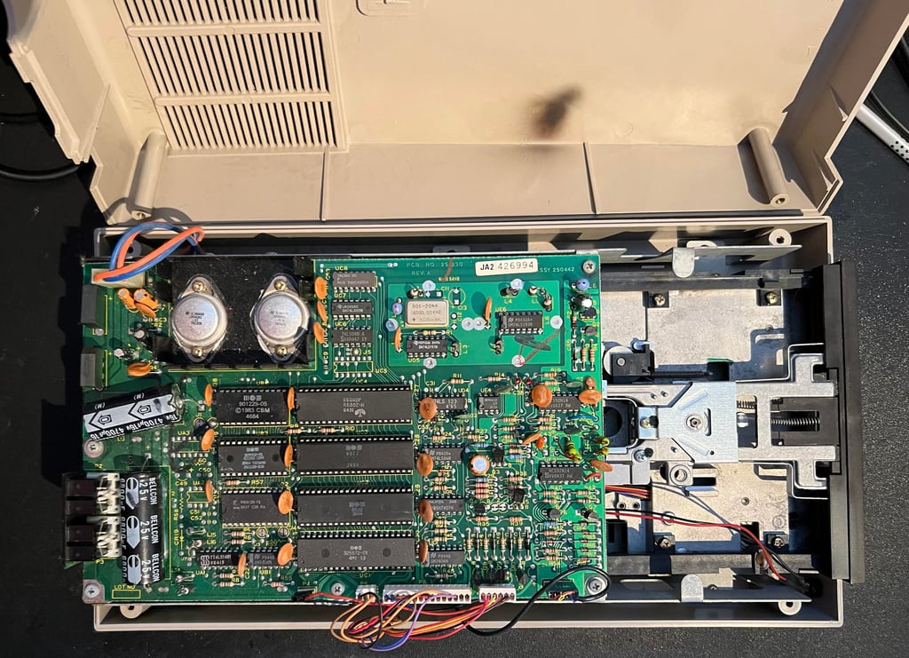
The seven screws holding the PCB are removed (see yellow squares and lines). Note that two of these screws are mounted on the side of the voltage regulators heat sink (during some refurbishing tasks these two screws will be put back when needed to attach the PCB to the chassis). Then the six screws holding the inner chassis to the bottom cover are removed (blue squares). Note that in the picture below only three of these screws (blue squares) are shown - there are three identical on the opposite side.

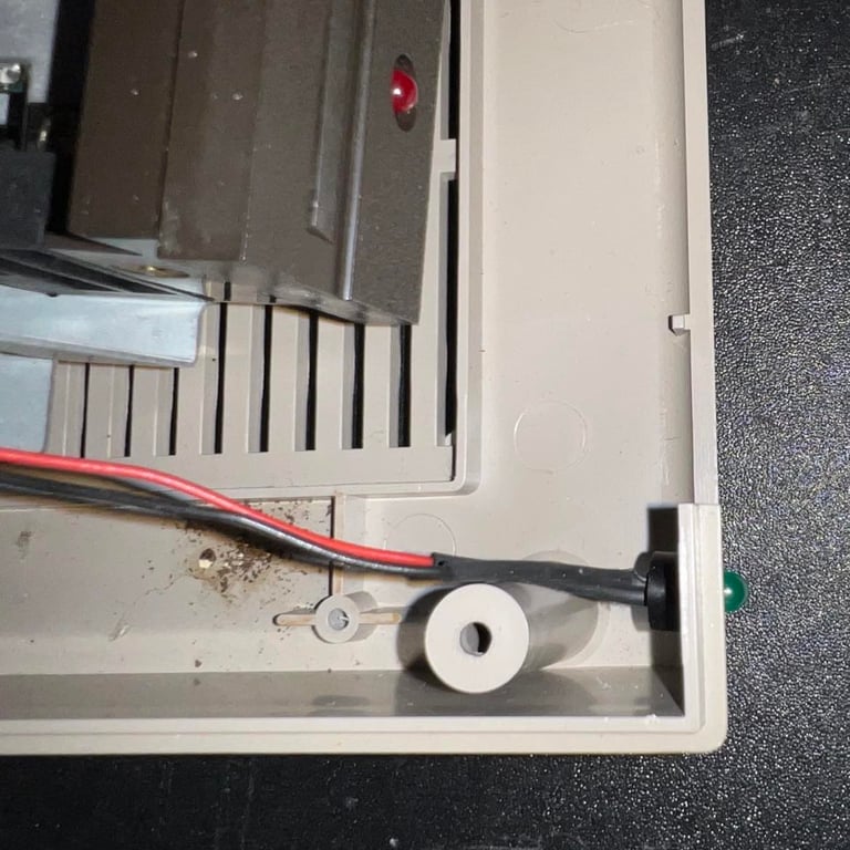
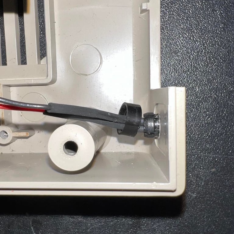
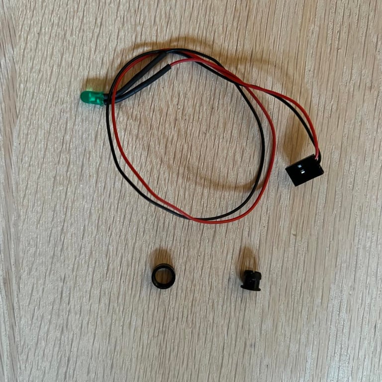
Before the interior is completely lifted out of the bottom cover the LED is removed. This is done by:
Removing the LED connector from the mainboard
Removing the small plastic ring from the LED holder
Pushing the LED from the outside towards the inside. The LED will then "pop" out from the plastic holder
Pushing the LED holder from the inside towards the outside. Using a pair of pliers while squeezing and pushing the holder will help.
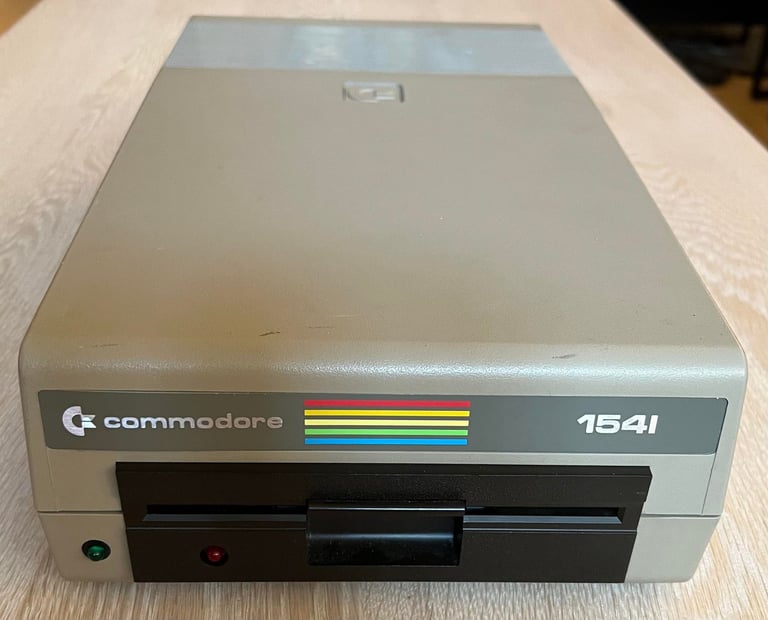
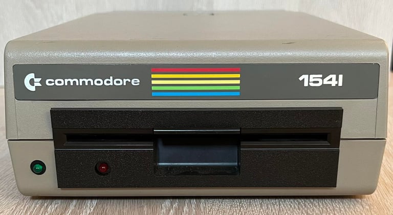
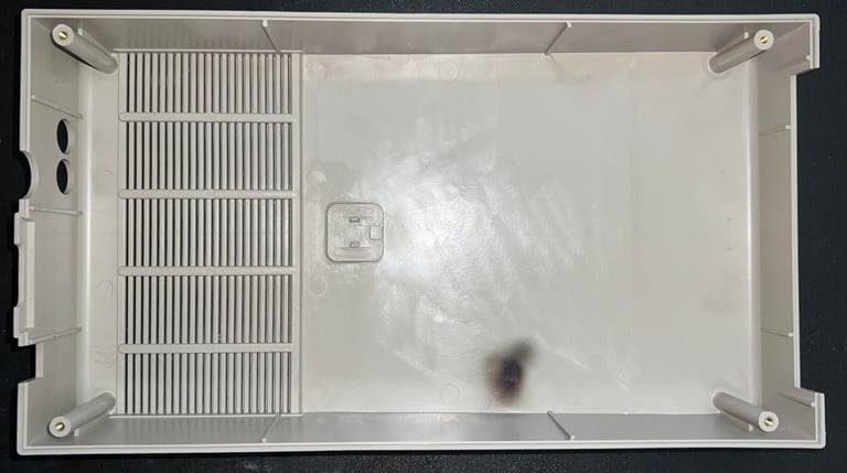
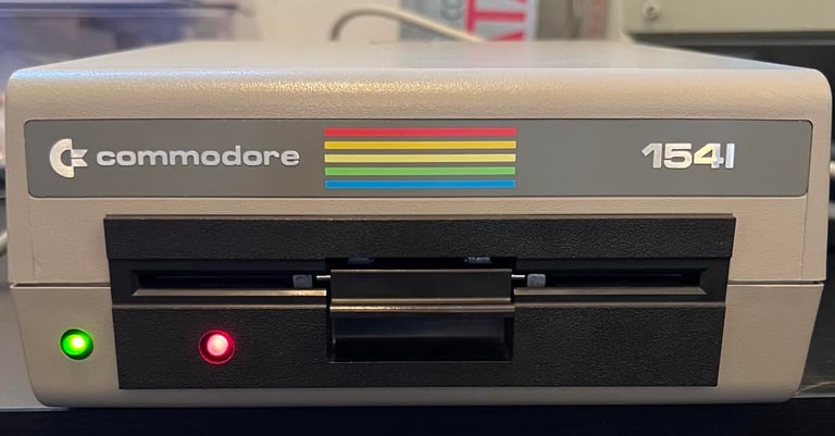
The interior is now lifted out of the bottom cover. Then the top- and bottom cover is cleaned thoroughly with mild soap water. Some of the stains are removed with isopropanol and glass cleaning spray. Also, the top- and bottom cover are placed outside in the sun (for some subrighting). The covers were not very yellowed, but I think it was a good thing to get some sunbrighting anyway.
The sticker on the front was only partly loose. So some small amount of glue does the trick - no problems there. Below are some pictures from the sunbrighting and the result of the cleaning.
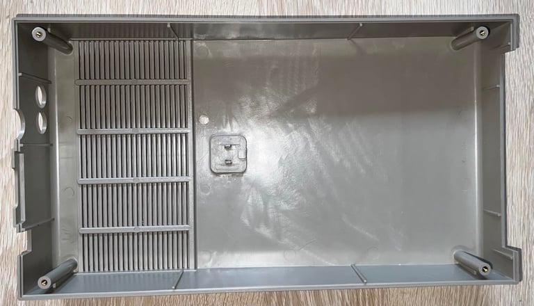
Note: the odd looking "burn mark" on the inside was nothing but dirt and fat. So everything is easily removed with some soap water and isopropanol.


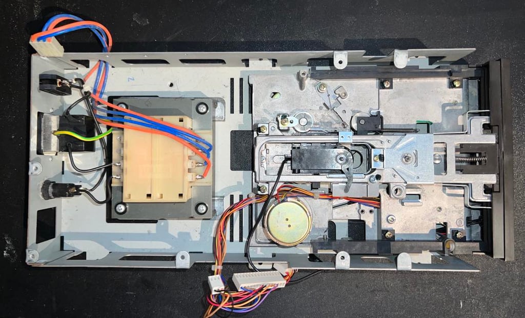
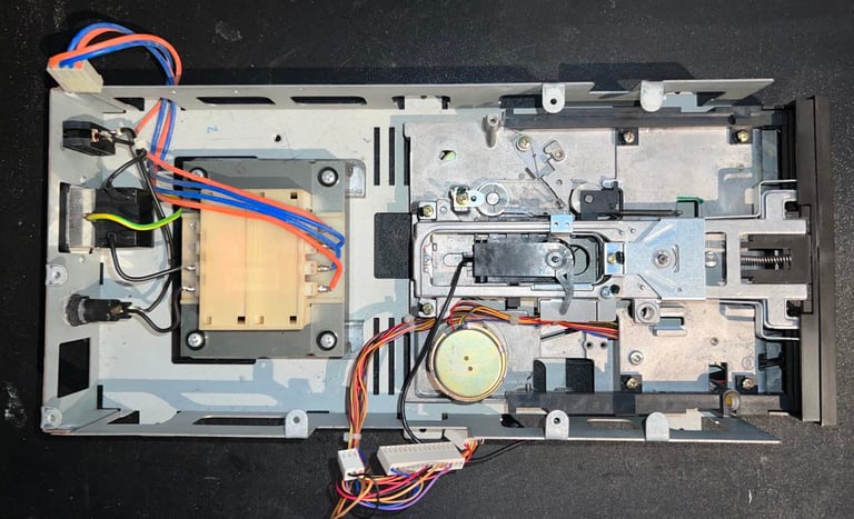
PCBs - Cleaning and inspection
There are two PCBs in the 1541:
Mainboard with most of the logic
A smaller PCB used to control the motor
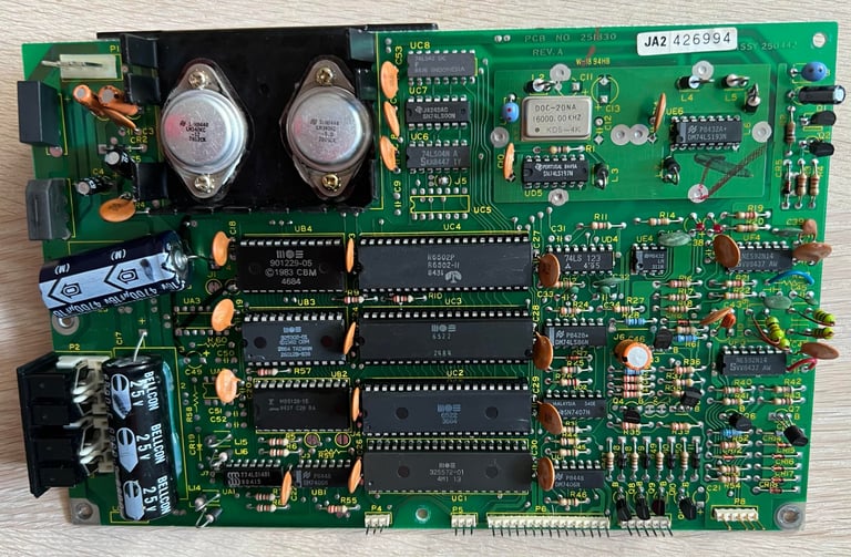
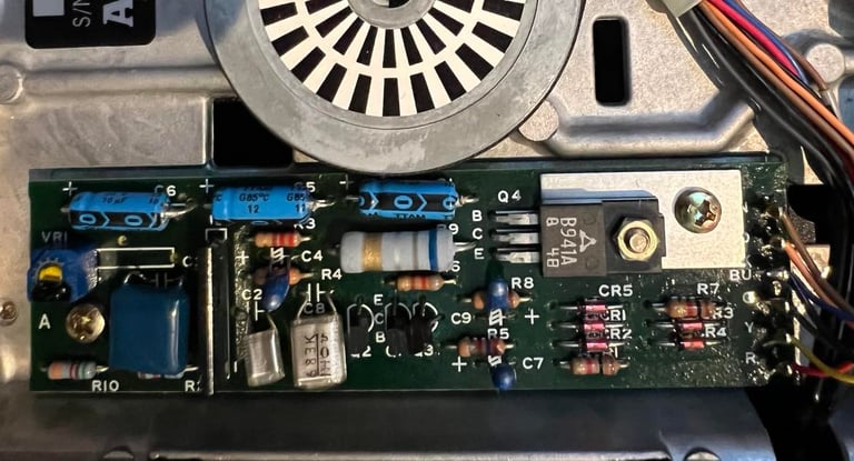
Mainboard
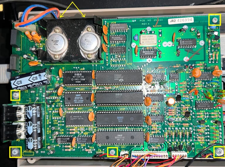
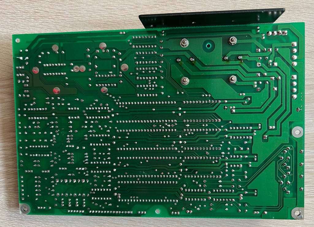
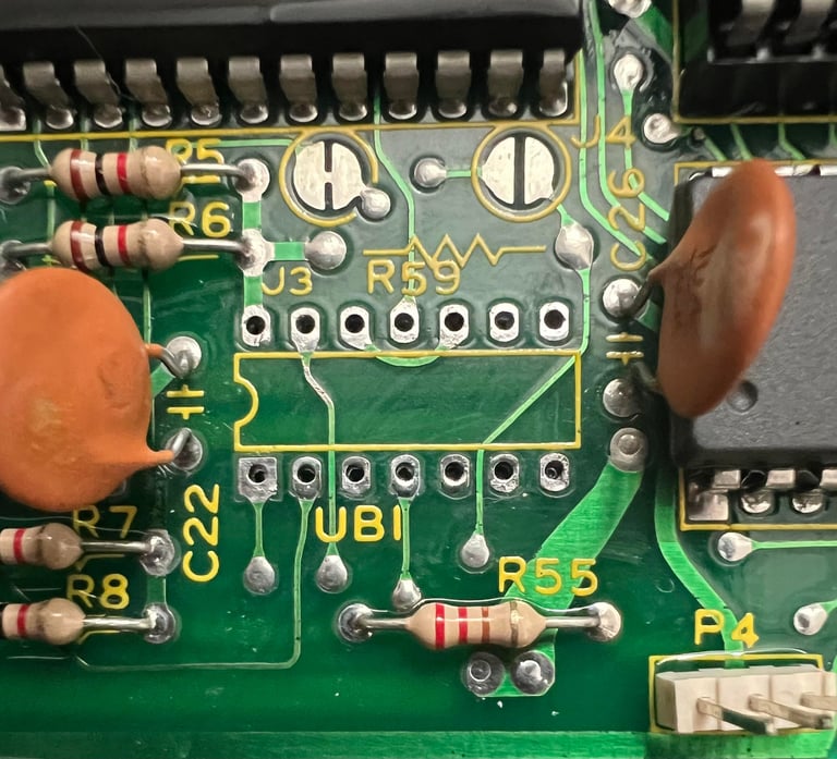
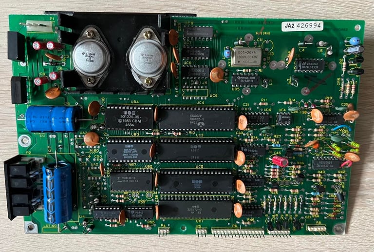
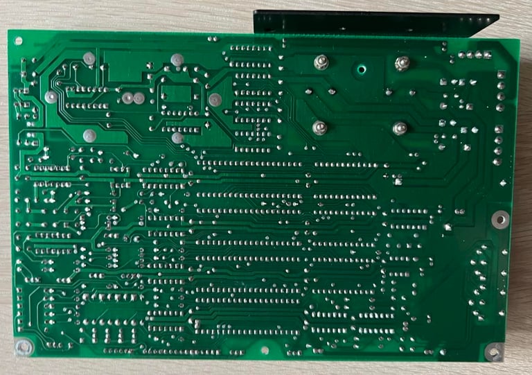
I start with the mainboard since this also (probably) needs repair.This is a PCB NO 251830 (Rev A) / Assy 250442 mainboard. To get the mainboard out of the 1541 all the connectors and the seven machine screws are removed (yellow squares).

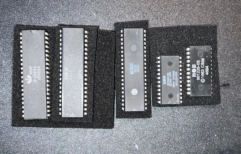
Socketed chips are removed first, and then the PCB is cleaned with some soapy water and a soft paint brush. While it dries for about 48 hours it is also sprayed with isopropanol once in a while to make sure all water is evaporated. The socket in UB3 (one of the DOS ROM chips) had a pin which was quite oxidized, but after cleaning looks good.
Below are some pictures of the mainboard after the initial cleaning.


Visual inspection
The mainboard looks to be in very good condition. But even after initial cleaning with soapy water there are still some dirt and grease which needs to be removed with isopropanol and cotton swabs. Nevertheless, I can not see any immediate problem which would case the drive not to operate - so my guess it that the fault is probably one or several faulty chips.
In the table below is a list of all the main chips installed on the mainboard. Note that it is normal that several of the chips were socketed at production time - so this is not a sign of rework.
As can be seen in the table above all of the chips are date coded in 1984. And the latest is in week 46 which would indicate that this drive was assembled sometime late in 1984 - perhaps a Christmas present? Also there is a sticker on the spindle motor saying "05 Oct 1984" which supports this time estimate.
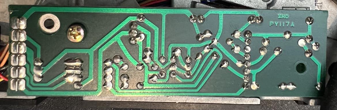
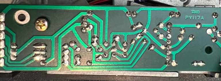
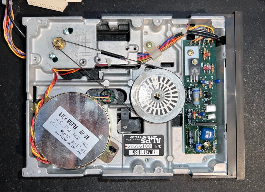
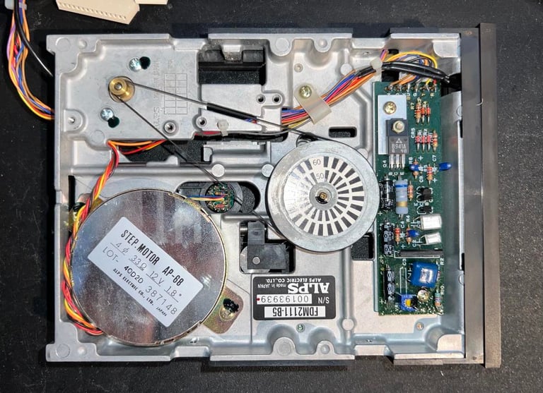
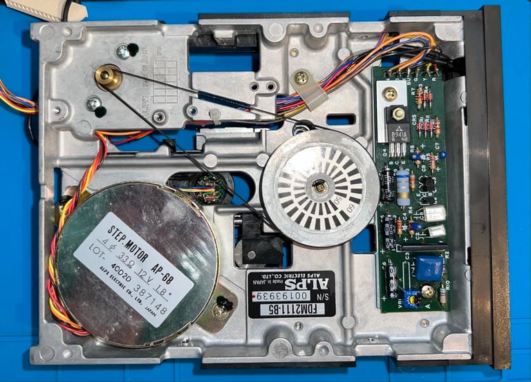
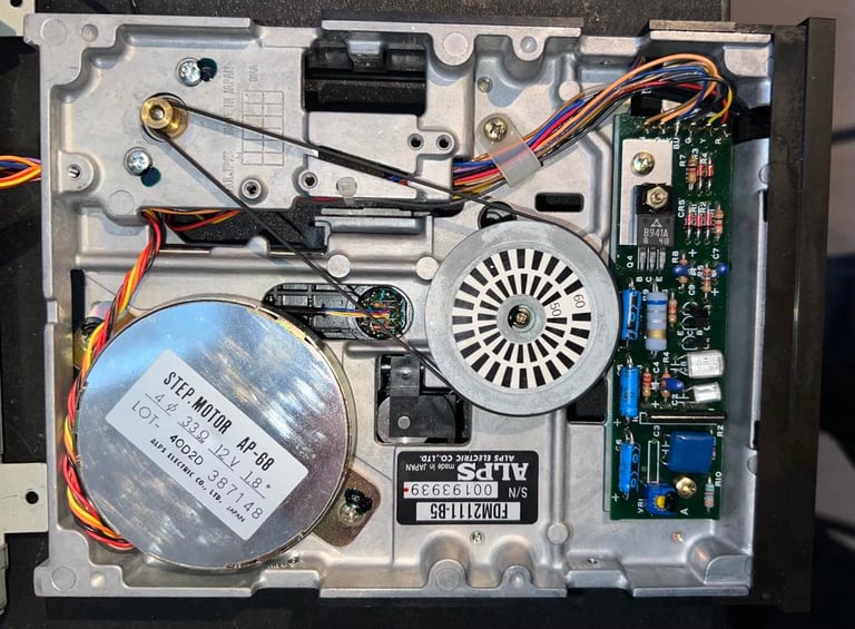
Motor unit
The motor unit PCB is found on the underside of the floppy drive together with the flywheel and drive belt. This is a PY117A revision of the PCB which is quite common. The front of the PCB looks to be in good condition - it is somwhat sticky and dirty, but I can not see any sign of corrosion or damage.

There are two screws holding the motor unit PCB to the chassis (yellow squares). These two are removed and then the PCB is lifted out from the drive. As seen from the picture below, this PCB is full of sticky flux residue. This is not a real problem, but it is good practice to clean this off. Anyway, the backside of the PCB looks to be in very good condition also. No sign of corrosion or other damage.
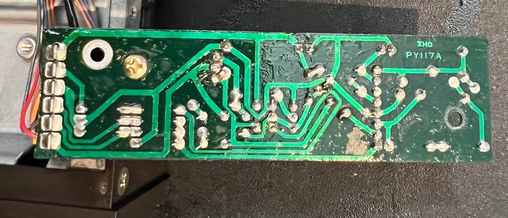
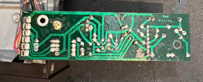
Both the front and the back of the PCB are cleaned with isopropanol on a Q-tip/tooth brush. And then wiped clean with a micro fibre cloth/Q-tip. The result is very good - see pictures below of the PCBs after cleaning.

Mainboard - Repair
Troubleshooting strategy
I know that the 1541 floppy drive is not completely dead: when power-on it boots up normally (the red LED goes on and then goes off after a few seconds). This indicates that the CPU is executing the boot-up code in the ROM chips. I think the problem lies is around the serial interface circuitry. When I type commands such as LOAD "$",8 nothing happens. Only the message "SEARCHING FOR $", but no error message such as "?FILE NOT FOUND ERROR" or "?DEVICE NOT PRESENT ERROR". To me this indicates that communication is lost between the Commodore 64 and the 1541 floppy drive.
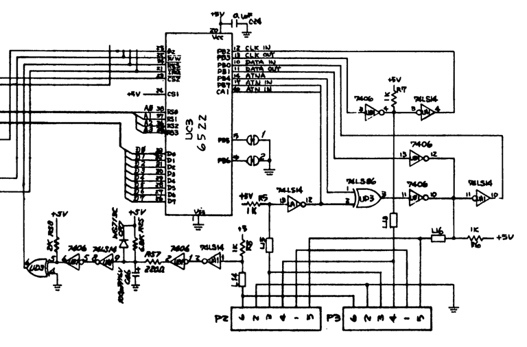
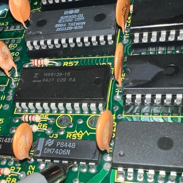
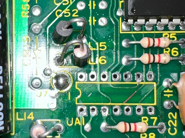
From the schematics in the 1541 service manual there are three ICs used in the serial interface circuitry: UC3 6522 (VIA#1), UB1 7406 and UA1 74LS14. My first strategy is to check these for any faults.

Repair attempt #1
While the disk drive is powered on I check if any of the three ICs are hotter than normal as a sign of a short circuit, but all chips feel normal. Next, I power off and replace the UC3 VIA#1 6522 chip with a known working replacement. But alas, the problem still persist. Still "SEARCHING FOR $", but there are no sign of life in the disk drive.
Repair attempt #2
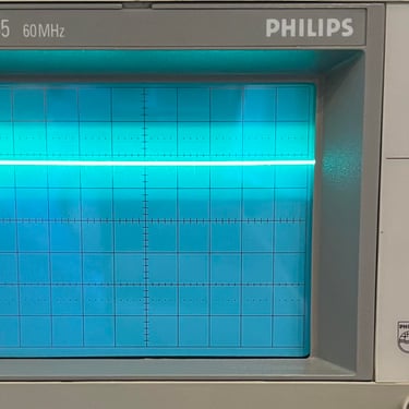
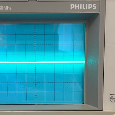
I check the signals on UB1 7406 with the oscilloscope. The 7406 is a 6 x hex inverter which inverts each of the inputs (e.g. HIGH in -> LOW out). And here I notice something which does not seem right. On pin#13 is a LOW, but on pin#12 there is a HIGH. But this output is also connected to pin#10 of the same chip, pin#11 on UA1 (7414) and the 1k pull-up resistor. Another signal which is strange is on pin #5 on UB1. As seen from the picture gallery below the signal on pin #5 is a flat 1.8 V and the output is a flat 0 V. If I remember correctly the trigger voltage for a "HIGH" is about 2 V so this could mean that the UB1 7406 is working fine, but that the UA1 74LS14 is giving the wrong output.
Even though I think that the culprit is UA1 74LS14 I choose to desolder and replace UB1 7406 since I do not have a spare 74LS14 at the moment. The chip is desoldered without damaging any trace or pads. See picture below.

A socket is soldered in and a new known working 7406 is installed. But... no surprise... the same problem. Still "SEARCHING FOR $" and no sign of life...
Repair attempt #3
Next step is to replace UA1 74LS14. Since I don´t have a replacement chip at the moment I borrow one from a working 1541. The UA1 is also desoldered without any damage to traces or pads (the picture below is taken before cleanup but shows that no pads were lifted).
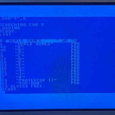
And with a "new" 74LS14 chip in place: SUCCESS! It now seems to be working as it should again. See video below for a short test after repair. Note that this is only a short test - so there could still be more problems, but now it can load games at least.

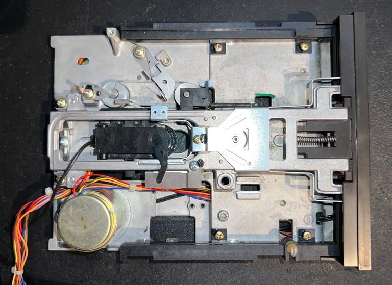
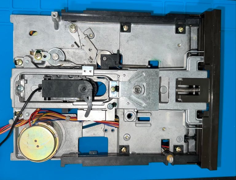
Interior mechanics
When the mainboard PCB is removed the interior mechanics is revealed. As seen from the picture below the interior looks to be in quite good condition - some dust and grease, but all major parts seems to be undamaged and so signs of corrosion.
Note: when removing all the connectors from the mainboard it is wise to mark (or take a picture) of how the connectors where set. If you put the connectors the wrong way, or miss some pins, you risk damaging critical components such as motor(s), R/W head and chips!
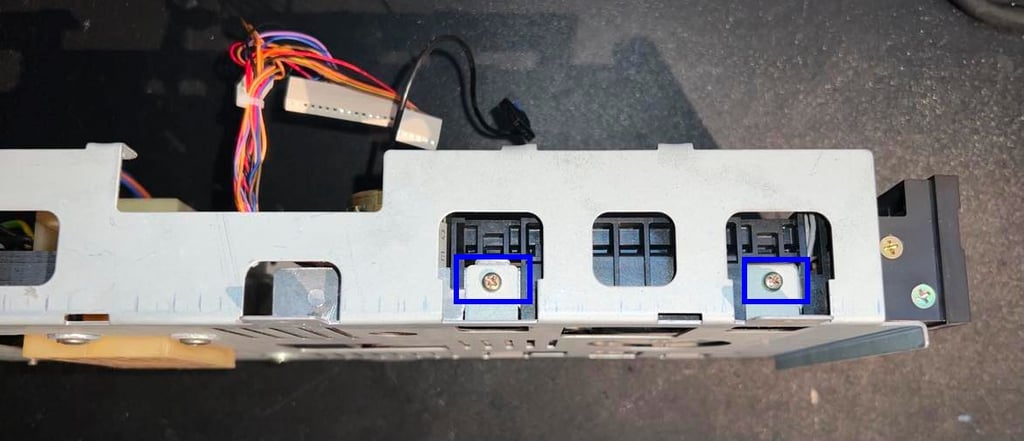
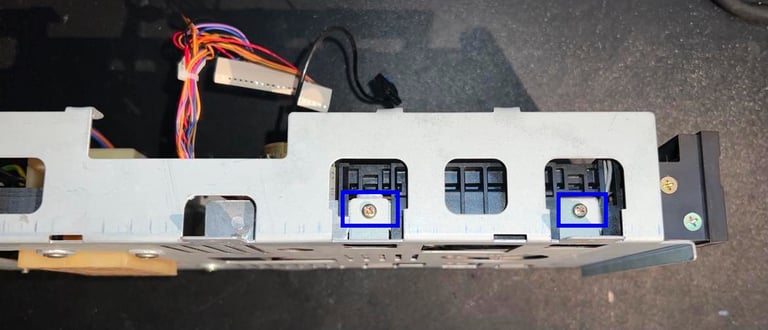
Cleaning and inspecting the bottom chassis
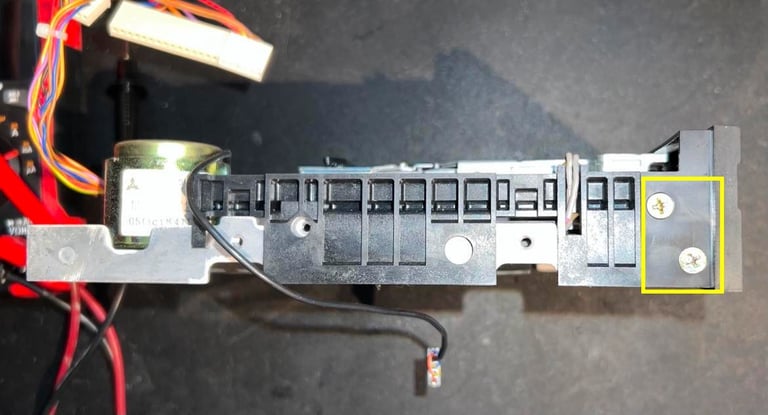
The floppy drive is removed from the bottom chassis. This is done by removing the four screws holding it in place. There are two screws on each side of the floppy drive (see picture below for one of the sides - blue squares).
The floppy drive is then partially lifted and then carefully pulled out of the opening (to the right seen from the picture above). It is a good idea to do this carefully so that none of the components on underside of the floppy drive are damaged (there are no shield protecting these).
With the floppy drive out of the way the bottom metal chassis is cleaned with isopropanol. The transformer looks to be in good condition also - so signs of melting, corrosion or any other damage. Below is a picture of the metal chassis after cleaning.

Cleaning, inspecting and lubricating the floppy drive
This is floppy drive is of the ALPS brand which has the reputation of being more reliable than Newtronics floppy drives in regards of the lifetime of the R/W head. As seen from the pictures below both sides of the drive seems to be in good condition. Only some small amounts of dust and dirt, but otherwise no sign of damage or corrosion.

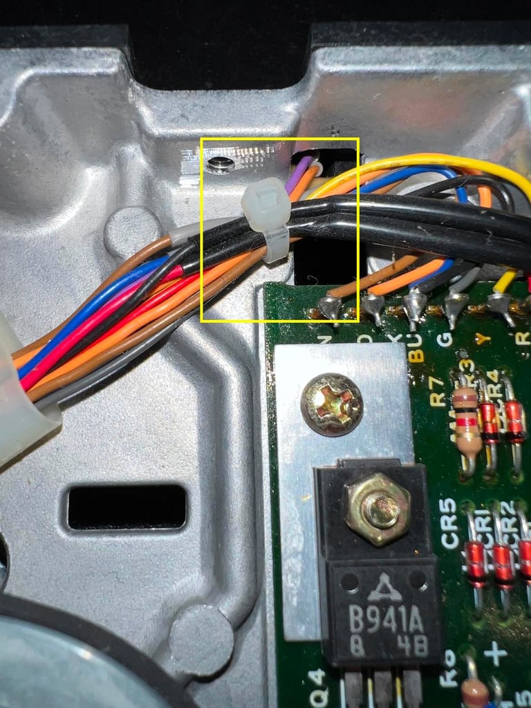
Before starting to partially remove the front cover the cable tie on the underside of the floppy drive holding the wires is cut. This is to make sure the LED cable is not preventing the front cover from being partially removed (yellow square).
The front cover is carefully pulled away (only partially) so that the plastic door assembly is allowed to be released. In the picture below this is shown - the front cover is partially removed, and the door assembly is released just above the front cover.

To access all parts of the floppy drive the four screws at the front cover are removed first. In the picture below two of the screws are shown (yellow square). The two others are - surprise! surprise! - on the opposite side of the floppy drive.

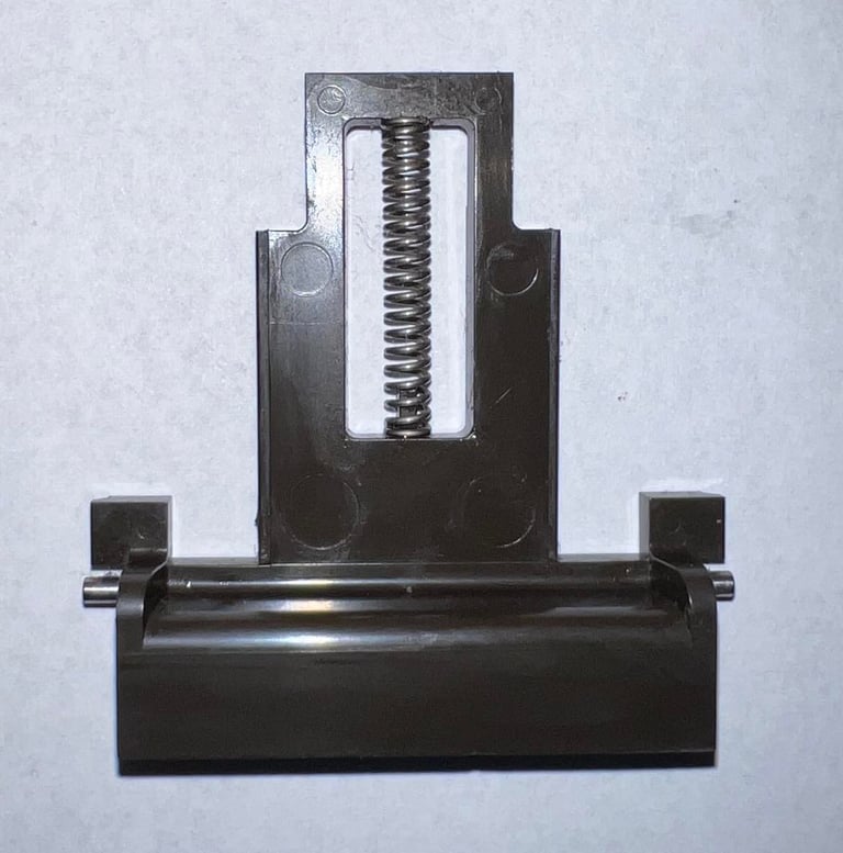
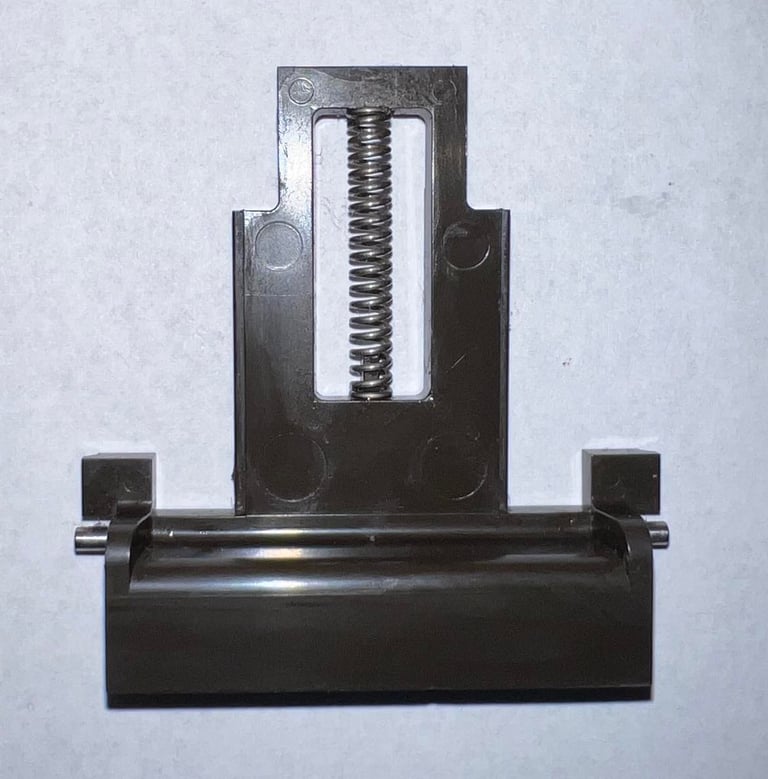
Read/write (R/W) head
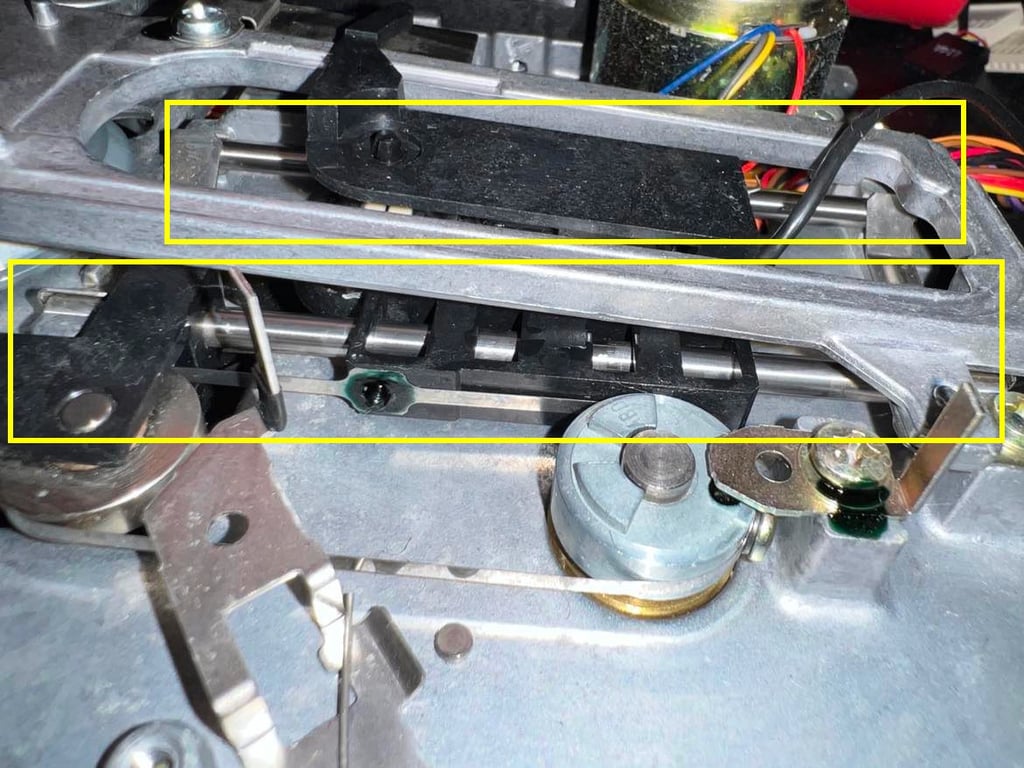
In order for the floppy drive to operate correctly the R/W head needs to be clean. The R/W head is cleaned with some isopropanol on a Q-tip. Not that it was very dirty, but it is good practice to do this as part of the refurbishment. Below is a picture of the R/W head after cleaning. Note; when cleaning the R/W head make sure not to lift the top pad more than absolutely necessary. There is a small spring at the end of the mechanism which is can be damaged if you lift too high. As the 1541 is a single sided floppy drive there is only one R/W head to clean.
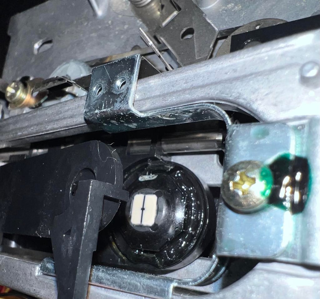

To make sure that the R/W head can move from track 1 to 35 the rails are cleaned with isopropanol and Q-tip. After cleaning the rails are then lubricated with some sewing machine oil. See picture below (the yellow squares indicate the position of the two rails). Note; make sure that no oil is spilled near the R/W head!

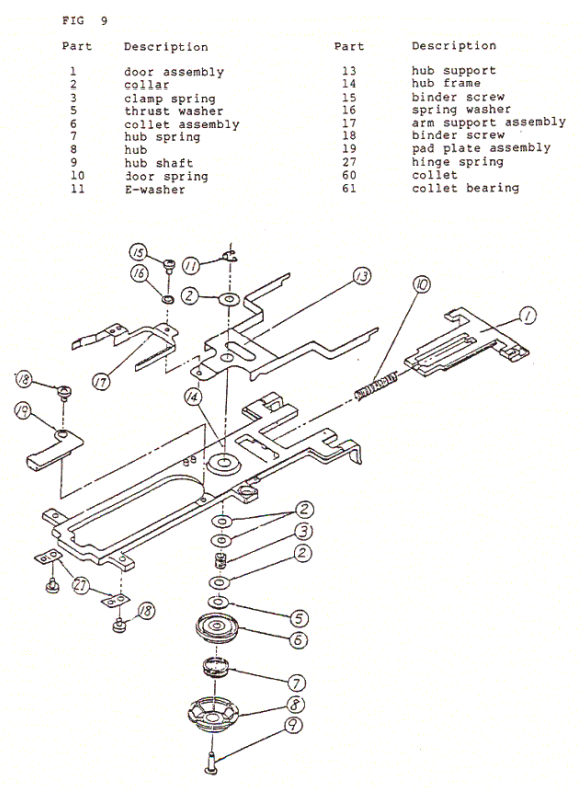
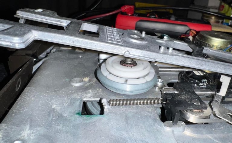
Spindle hub mechanism
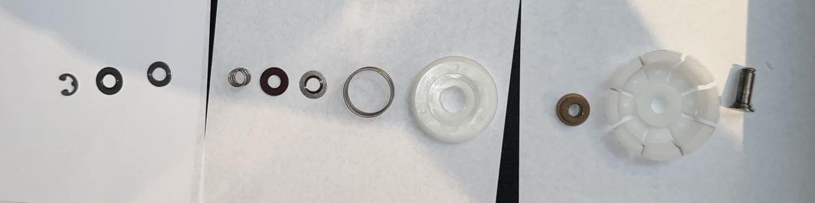
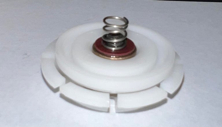
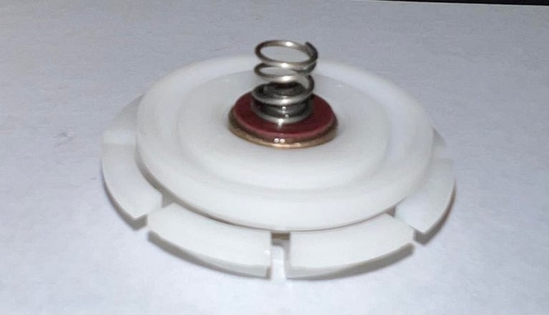
The rotating spindle hub can be quite "noisy" if it is not properly cleaned and lubricated. After almost 40 years this mechanism there are probably quite some dust particles and old grease stuck on this. But to clean this spindle hub the whole mechanism needs to be disassembled. Although not very difficult, it can be challenging to get all the small pieces back in the correct order. Below is an "exploded view" of the complete spindle hub mechanics used as reference.

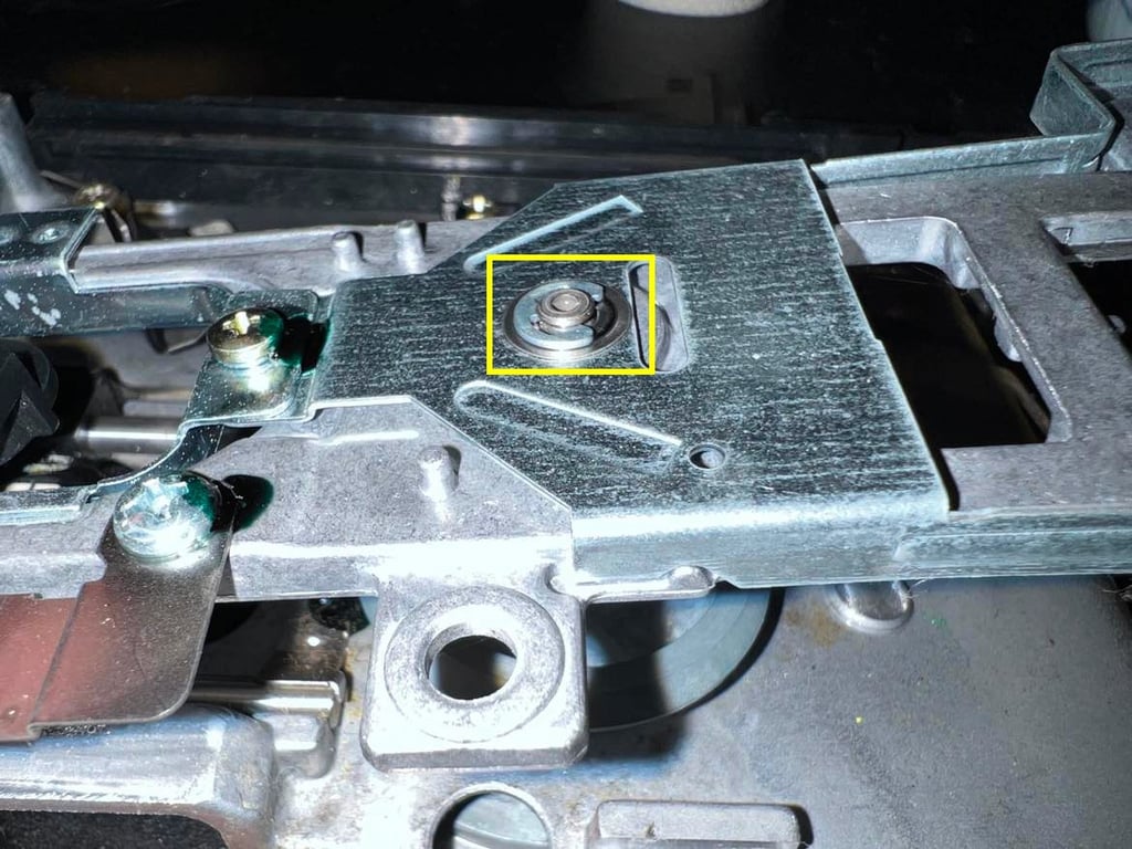
The first step is to remove the E-washer clip. See picture below. Note that when this E-washer is removed the hub will "fall down" so watch out for small parts flying all over the place!

When the hub frame is slightly lifted the spindle hub core is now possible lift out as "one piece".
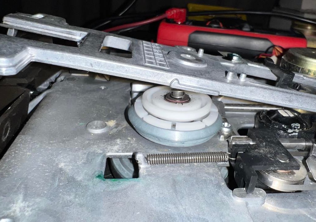
Each single part of the hub is cleaned with isopropanol on a Q-tip. And each part which is made of metal is lubricated with some sewing machine oil. This is quite tedious work, but it will help a great deal on reducing the noise from the spindle hub.

The door assembly and the spring are also cleaned with isopropanol. And the small notches in the hub frame where the door can slide back and forth are lubricated with sewing machine oil.
When all parts are cleaned and lubricated everything is assembled - ready for the initial testing.


Initial testing
Before the next stage of refurbishing the disk drive is tested for basic operations. This is to check if the disk drive is in need of:
Repair (more than already repaired)
Alignment
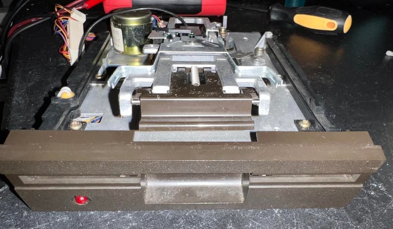
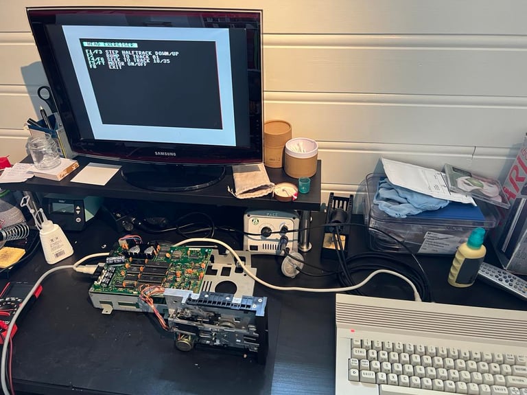
This initial testing is done with the floppy drive partially assembled. See picture below.
Voltages
The 1541 disk drive is supplied by two voltages; 12 VDC and 5 VDC. These are transformed, rectified an regulated inside the drive. In the table below the measured voltages are listed.
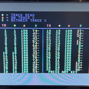
Resistances
There are three components in the 1541 which are made up of coils; the R/W head, the stepper motor and the spindle motor. A good indication to see if these work fine is to measure the resistance in the coils - see schematics below. The colors are found on the corresponding connector to the mainboard.
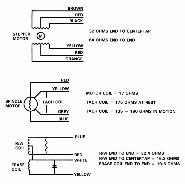

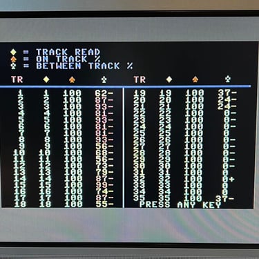
The results are listed in the table below. As can be seen from the table the spindle tach coil (rest) is higher than target. I am not sure if this indicates any issue, or if this is just due to another type/manufacturer of the spindle motor. This will be checked during the basic testing. All other values looks to be within target tolerances.

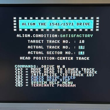
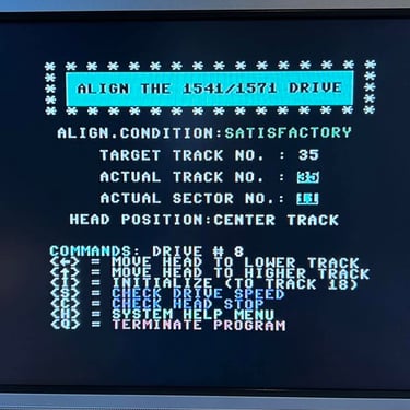
Track 0, 1, 18 and 35 positions
The R/W head can read data between track 1 to 35, and in addition it can move all the way to track 0. The reason for the drive to move all the way to track 0 is that this is the absolute start of the drive position. By using the stepping motor the R/W head is moved - step by step - from track 1 to 35.
There are four positions which are checked:
Track 0 (absolute start of disk - no data read)
Track 1 (normal start of disk - first data track read)
Track 18 (initial position of disk on boot - BAM and directory)
Track 35 (normal end of disk - last data track read)
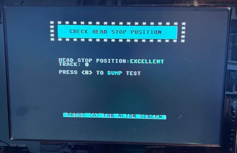
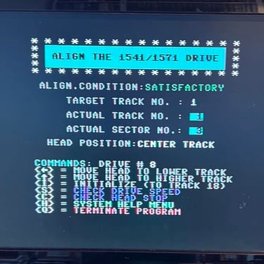
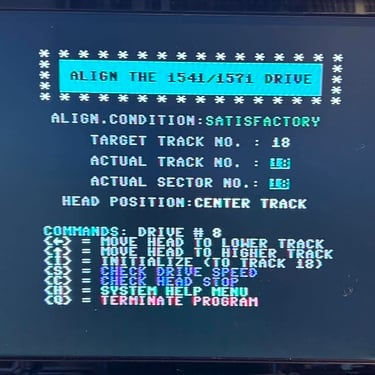
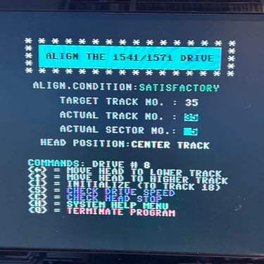
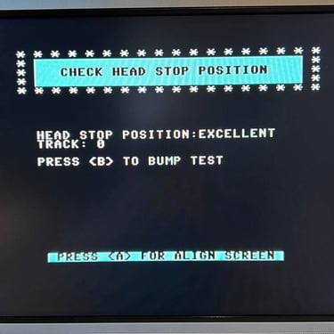
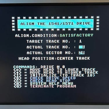
Track 0 is tested with the 1541/1571 drive alignment software. See picture below.

Track 1 is checked visually. As seen from the schematics below there should be about 0.35 mm between the stop ring and the stopper.
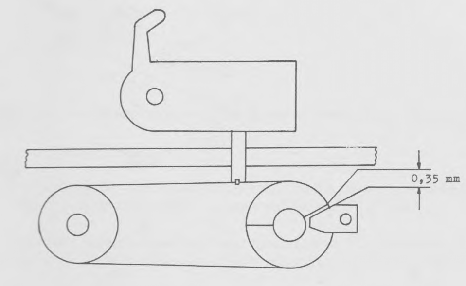
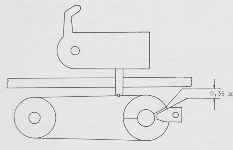
As seen from the picture below this space is not 0.35 mm. This could mean that this needs to be adjusted. But I will not do that yet - if the alignment test passes it is probably better to leave it like this. If track 1 to 35 can be read 100 % with original disks it means that the position of track 1 is ok - even if the gap is <0.35 mm.
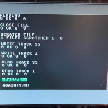
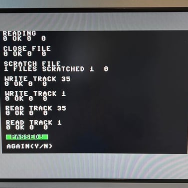
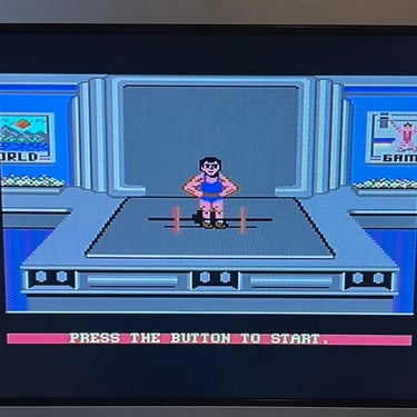
Track 1,18 and 35 are finally tested visually with the head exerciser found on the 1541 Test & Diagnostics cartridge. In the video below you can see the head move from track 1, 18 and 35.

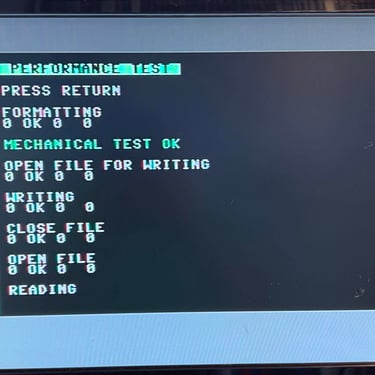
Basic functionality
In the table below all the functionality tests are listed. Most of the test are done with the 1541 Test & Diagnostics cartridge (World of Jani) and 1541/1571 Drive alignment software from Free Spirit Software inc. This table will be used as a summary of the initial testing - detailed test results will follow after the table.
Below are some pictures from the testing process. Click to enlarge.
Conclusion stage #1
The initial testing is by no means an extensive testing. But it looks to me that the drive´s basic functionality is in place so I will continue with stage 2 - replacing old parts.
STAGE #2:
Replacing old parts
Replacing the drive belt
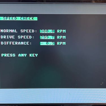
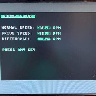
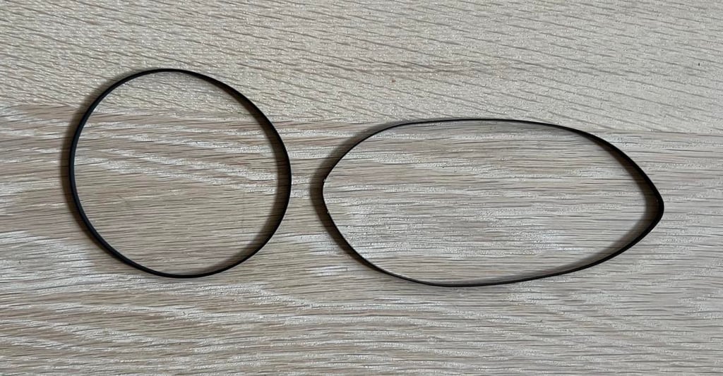
After almost 40 years the motor belt driving the flywheel is worn out. Much of its flexibility and "grip" is lost and you can experience that the belt just fall out of position. So changing the motor belt is both smart and easy operation. Note; after changing the motor belt it is a good idea to check and adjust the rotational speed of the flywheel (this adjustment is probably required also after the electrolytic capacitors are replaced).
I purchase new belt from Console5. To remove the belt is is just to lift it from the motor shaft and the flywheel - no screws needs removing. In the picture below the new belt is installed.

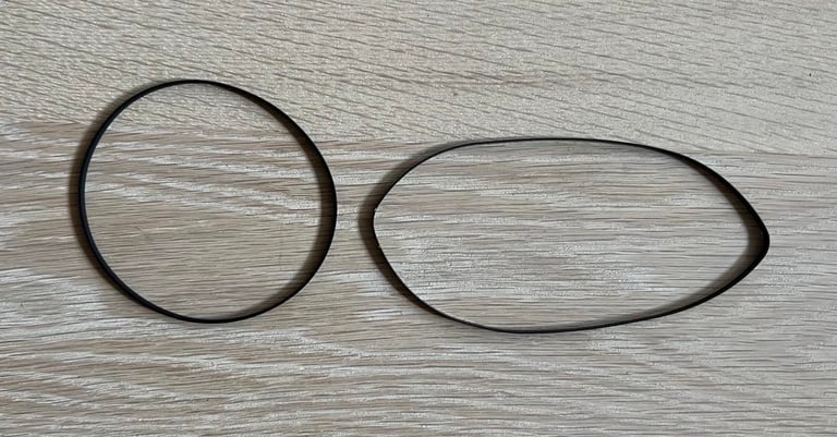
As seen from the picture below, the difference between the old and new drive belt is significant. The old belt to the right is deformed (following the shape of the spindle motor shaft and the flywheel). While the new belt to the left is circular.
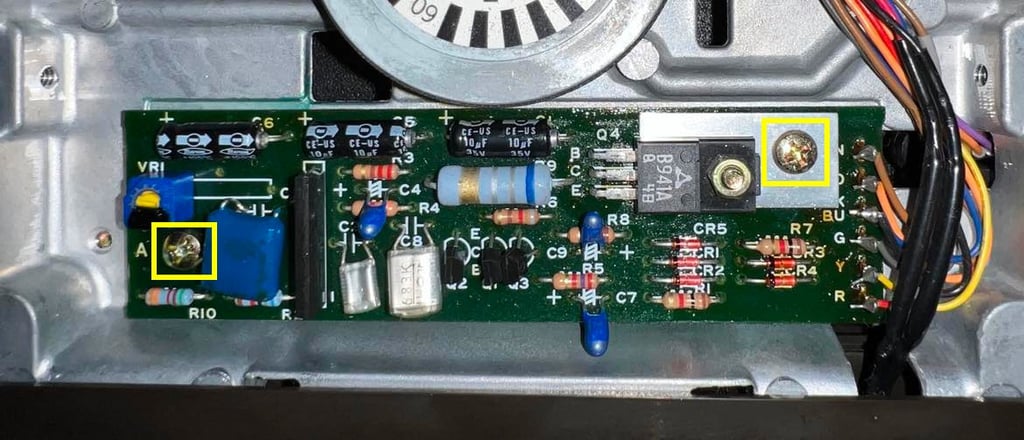
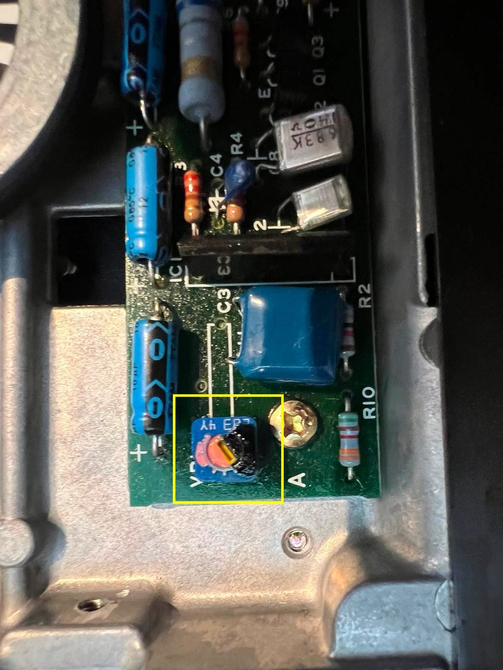
When the new belt is installed a quick check, and adjustment, is done to the rotational speed. To check the rotational speed the 1541 Test & Diagnostics cartridge is used. And while the disk is spinning the VR1 is carefully adjusted with a small flat screwdriver until about 300 RPM is reached. With the new belt in place the speed is reduced to 284 RPM so VR1 is adjusted so that the speed is around 300 RPM again. Below is a picture of the position of the VR1 potentiometer (yellow square). The potentiometer is "locked in place" using some borrowed fancy nail polish.

Replacing the electrolytic capacitors (mainboard)
The electrolytic capacitors are prone to dry out due to old age and excessive heat. Although it is not (usually) critical that a electrolytic capacitor dry out for the floppy drive to function I think it is good practice to replace them. Old capacitors with "wrong" ESR value and/or different capacitance than original can give odd behaviour to the drive.
As seen in the capacitor list for this mainboard there are eight electrolytic capacitors. I use only quality capacitors which have a temperature rating of 105 degrees Celcius from Panasonic/Vishay and Wurth Electronics. This is higher than the original capacitors (which have only 85 degrees Celcius for many of the caps) - but there will be significant heat inside the 1541 floppy drive so it is recommended to use a slightly higher temperature rating.
On this mainboard C15 is also an electrolytic capacitor (10uF 35V), but according to the 1541 Service Manual C15 should be a 10 uF 25V tantalum capacitor. I am not sure why Commodore did replace this at production time, but I choose to replace it with an electrolytic capacitor also - just to be sure.
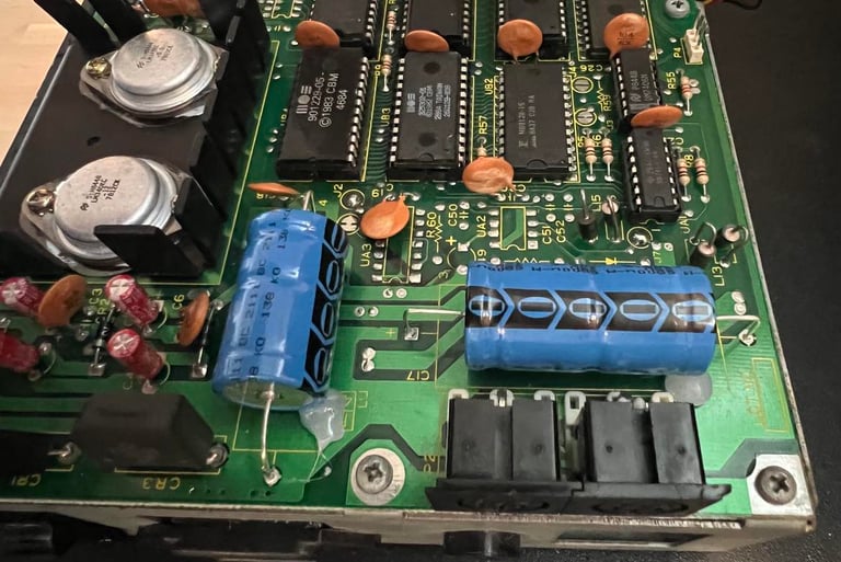
In the picture below the front- and backside of the mainboard is shown with the new electrolytic capacitors installed.


The two large capacitors are glued to the PCB - as they were originally from production. This is due to make sure the large capacitors are not damaged by vibration.

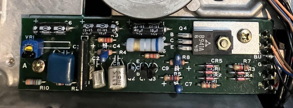
Replacing the electrolytic capacitors (motor control board)
There are only three 10 uF [35 V] axial electrolytic capacitors on the PCB connected to the motor. They are replaced with new quality capacitors from CDE/Illinois capacitors. See picture below.

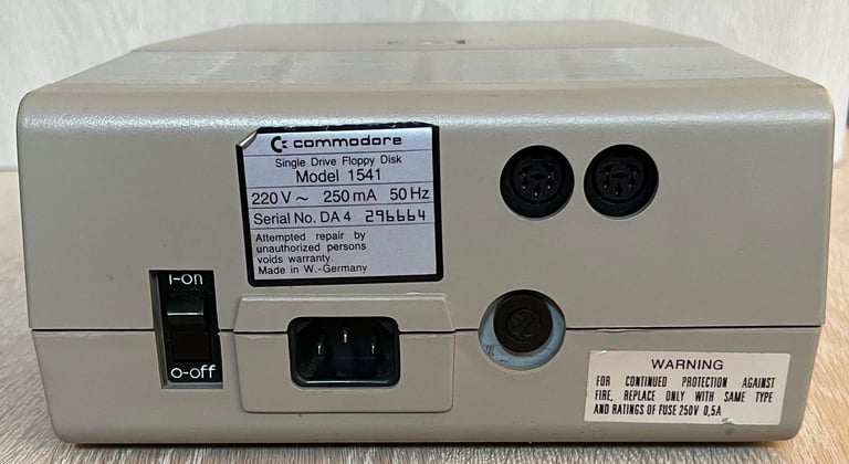
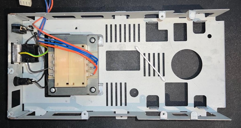
Reconfigure transformer input from 220 V AC to 240 V AC
WARNING: This part requires work on electrical components supplied with high voltages (up to 260 V). Danger of electrocution!
The purpose of this task is to reduce the input voltages supplied to the 12 V and 5 V voltage regulators. Reduction in input voltage will result in a reduction in the amount of power the regulators need to waste as heat to supply the output voltages. Wasted heat warm up the whole disk drive which could reduce the lifespan of critical components.
This task is heavily inspired by iz8dwf on YouTube so I am grateful for learning about this solution.
Background theory
As can be seen from the schematics below (from the 1541 Service Manual) there are two different input configurations on the primary side of the transformer - both shown as "Input Volt +/- 10 %". The voltage can be connected to either connector configuration 1+2 or 1+3. When the floppy drive was produced probably sometime late 1984 the 1+2 configuration was used to support the 220 V AC input.

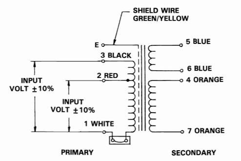

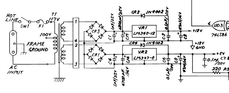
The two outputs on the secondary side of the transformer are connected to two bridge rectifiers (CR3 and CR1). See schematics below. These rectifiers will convert the AC to DC voltage which are supplied to the two voltage regulators VR1 (12 V) and VR2 (5 V). In order to generate the correct output voltages (12 V / 5 V) the regulators basically "waste" the abundant input voltage - and this waste is pure heat. So the less "waste" the better - resulting in less heat. Of course, the input can not be too low which then could result in the voltage regulator not being able to produce the correct output voltage.
Note that in the schematics, which are taken from the 1541 Service Manual, the AC input voltage on the primary side of the transformer is actually wired in 1+3 configuration. This is for the US market, but I don´t quite understand why they did it different in the European market.
Rewiring
The primary side of the transformer is rewired to support 230-240 V AC as is normal in Norway. A small additional wire is added to allow for future changes if necessary (the original wire is a bit short). In the table below are the measured results from the rewiring.
I am not sure about the current drawn from the voltage regulator, but if we assume currents in the range 0.5 to 1.0 ampere this reduction in voltage will result in a power reduction between 1.4 to 2.8 W which is quite a lot. This reduction in power will only result in less heat - the output voltage required for the floppy drive to operate is the same.
The voltage table at start of the "Initial testing" is updated after this operation.
Below are two pictures from this operation. The first picture shows the original wire configuration (1+2) while AC input is measured. The second picture shows the transformer after rewiring (note the small wire extension for easier future rewiring).
STAGE #3:
Testing and verification
The purpose of this stage is to test, and verify, that the 1541 floppy disk drive works as it should. Basic functionality were tested in stage #1 and now everything is re-tested and verified. A combination of software tools are used in this process - please see description of tools.
In the table below are the results and at the bottom some images from the testing are shown.
All test pass without any issues so the drive works as it should as far as I can see. In the gallery below are some pictures from the testing (click to enlarge).


Final result
"A picture worth a thousand words"
Below is a collection of the final result from the refurbishment of this 1541 floppy drive. Hope you like it! Click to enlarge!


Banner picture credits: Medvedev