
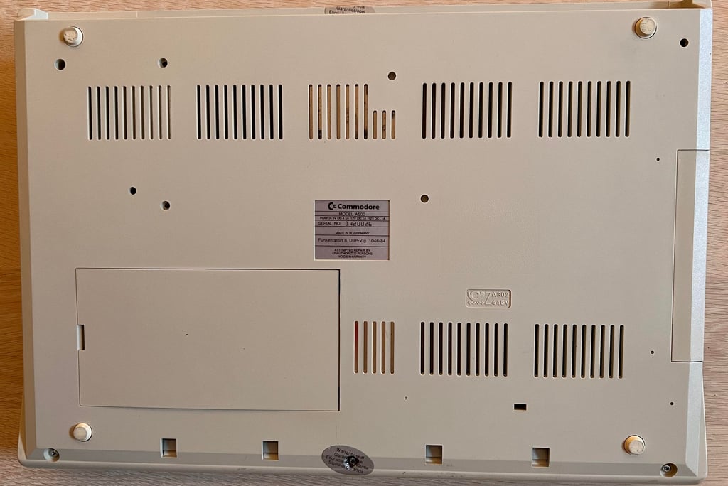
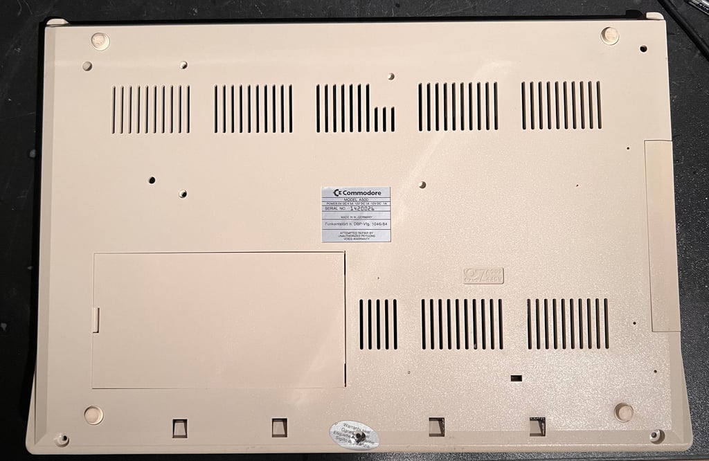
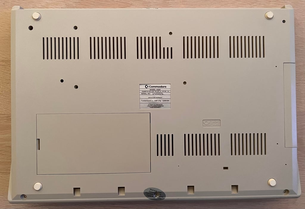
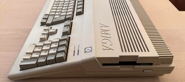
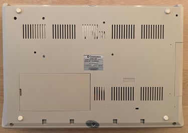
Amiga 500 [PAL]
Ser. No. 1420026
Assy 312510
Artwork 312513 REV 5
Starting point
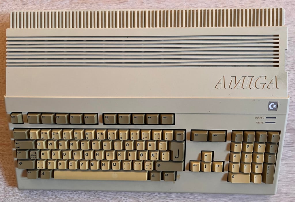
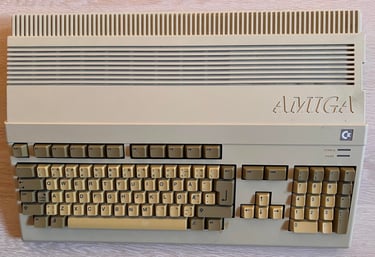
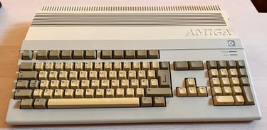
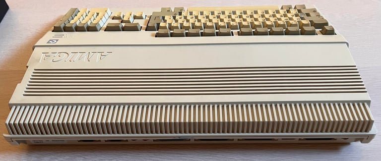
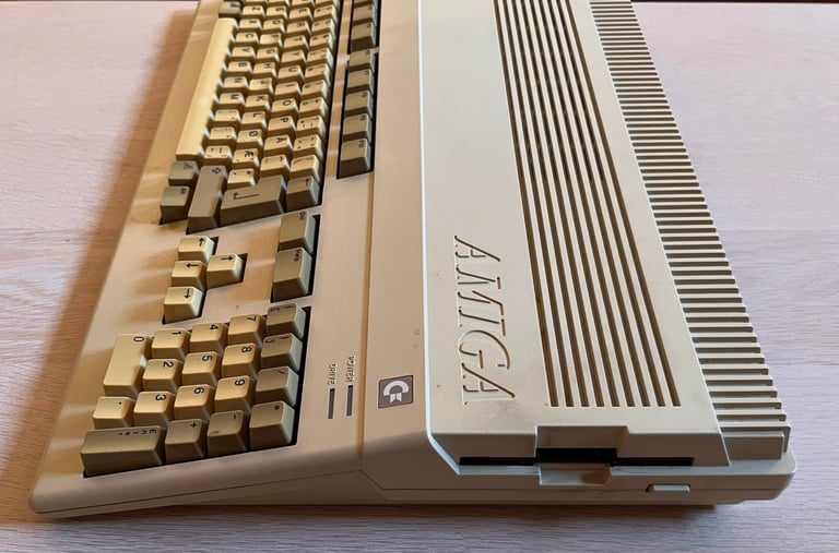
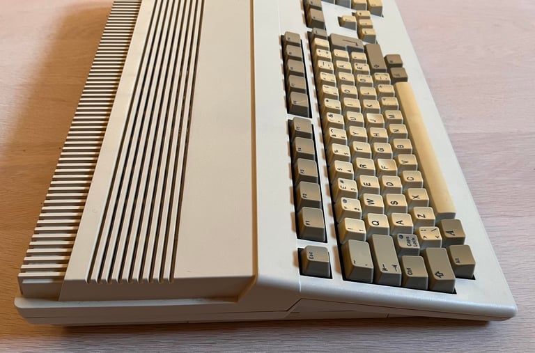
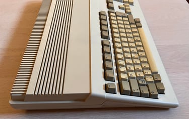
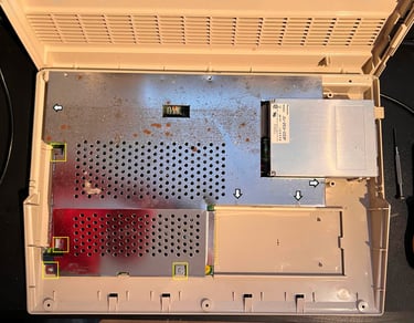
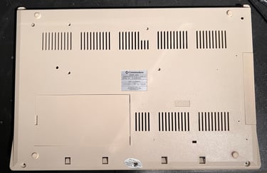
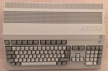
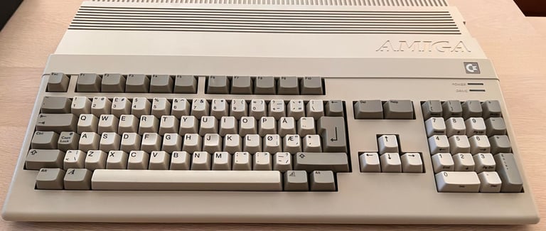
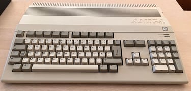
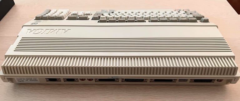
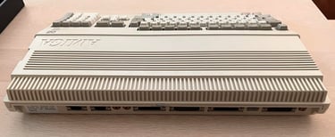
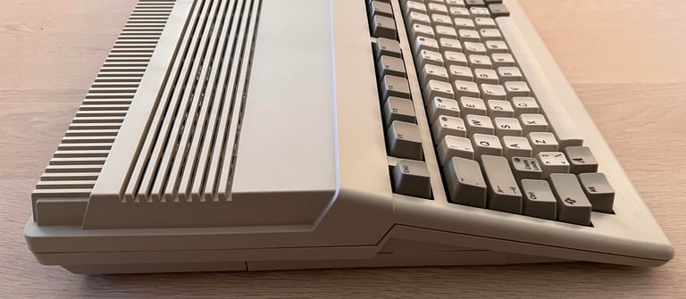
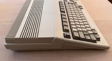
This Amiga 500 has come for some repair and refurbish. The machine is supposed to be in non-working condition. The machine looks otherwise to be in good condition. It is quite dirty, some severe stains and yellowed, but I can not see any visual damage.
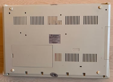
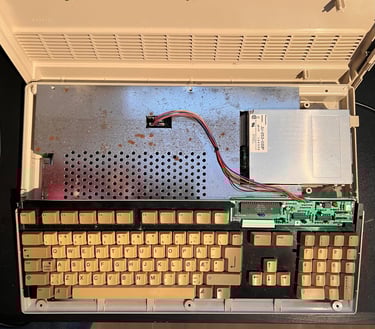
Below are some pictures of the machine before refurbish.


Refurbishment plan
To refurbish this Amiga 500 the plan is to do the following actions (several of them in parallell):
- Clean and retrobright the top- and bottom cover
- Clean, revive and retrobright the keyboard
- Repair and refurbish the main board
- Refurbish the internal disk drive
- Refurbish 512 kB RAM expansion card
- Verify operation by testing
Opens it up...
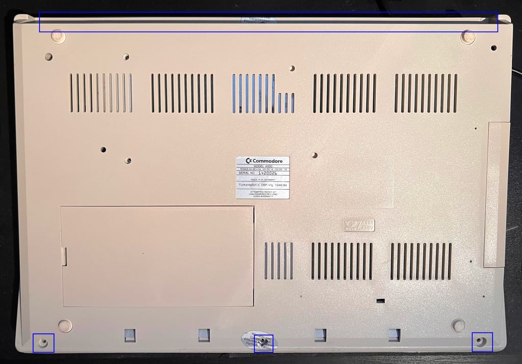
The Amiga 500 is place upside down and the six screws are removed. This will release the top cover from the bottom cover.

This reveals the inside of the Amiga. There is some dust inside, but otherwise looks good.
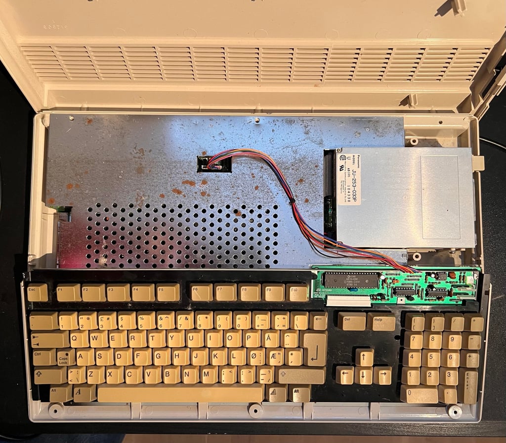
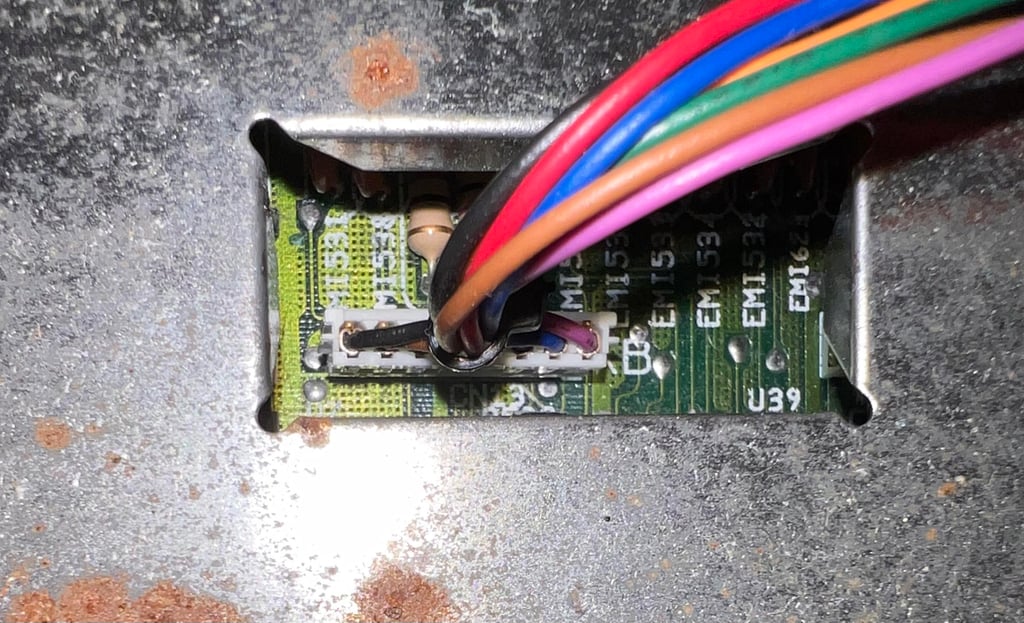
The keyboard connector is carefully removed by wiggling the connector sideways and then lifted.

To remove the RF-shield the four metal tabs (see arrows) are bent upright and the four torx screw are removed (yellow squares).
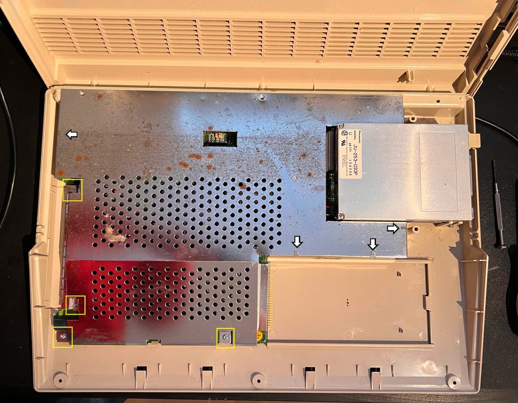
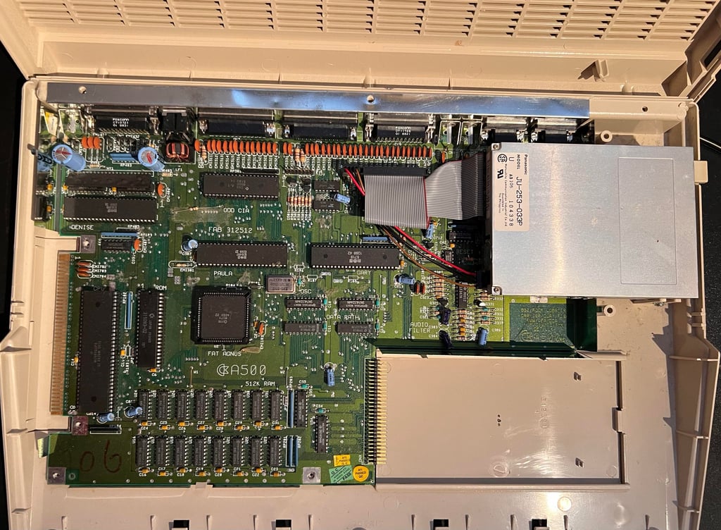
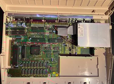
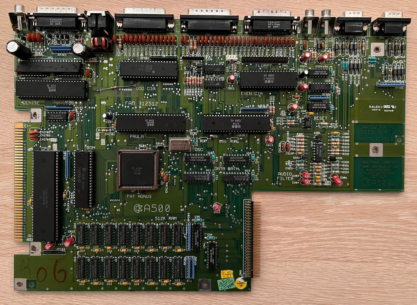
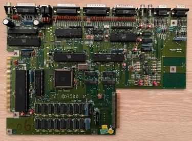
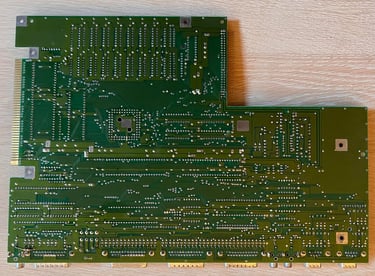
When the RF-shield is removed the mainboard is revealed. There is quite a lot of dust inside, but it looks to be intact.
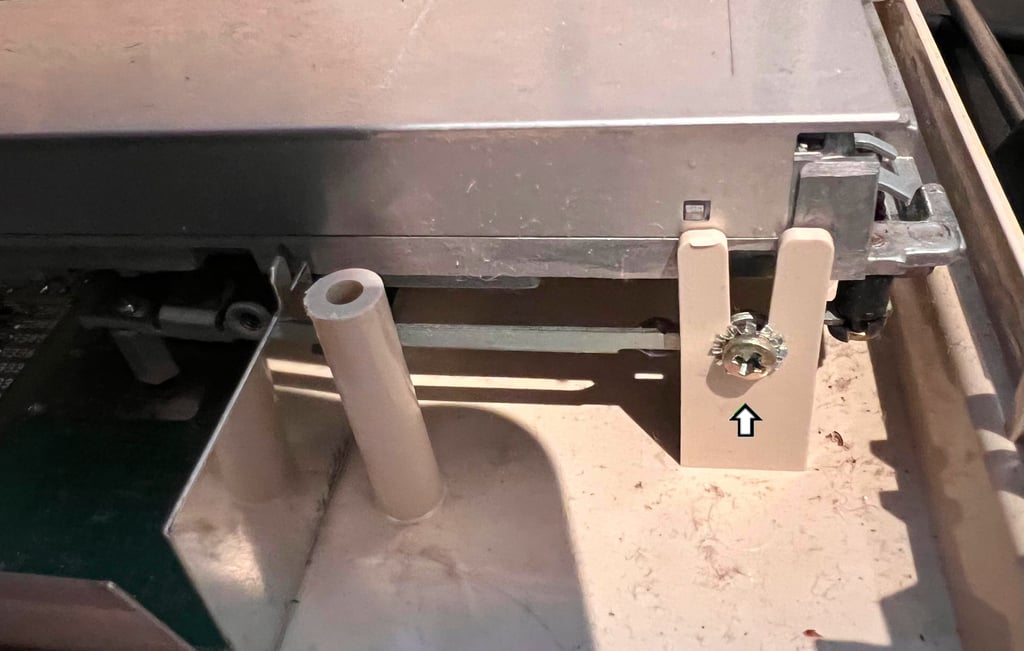
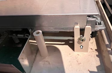
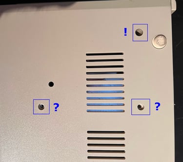
The internal disk drive is also removed. This is done by first removing the data- and power cable. Then the single screw and spacer on the side (see picture below) and a single screw on the back is removed. Note that there are two screws missing on the backside which should hold the drive in place. So someone has obviously been here before.
Exterior casing
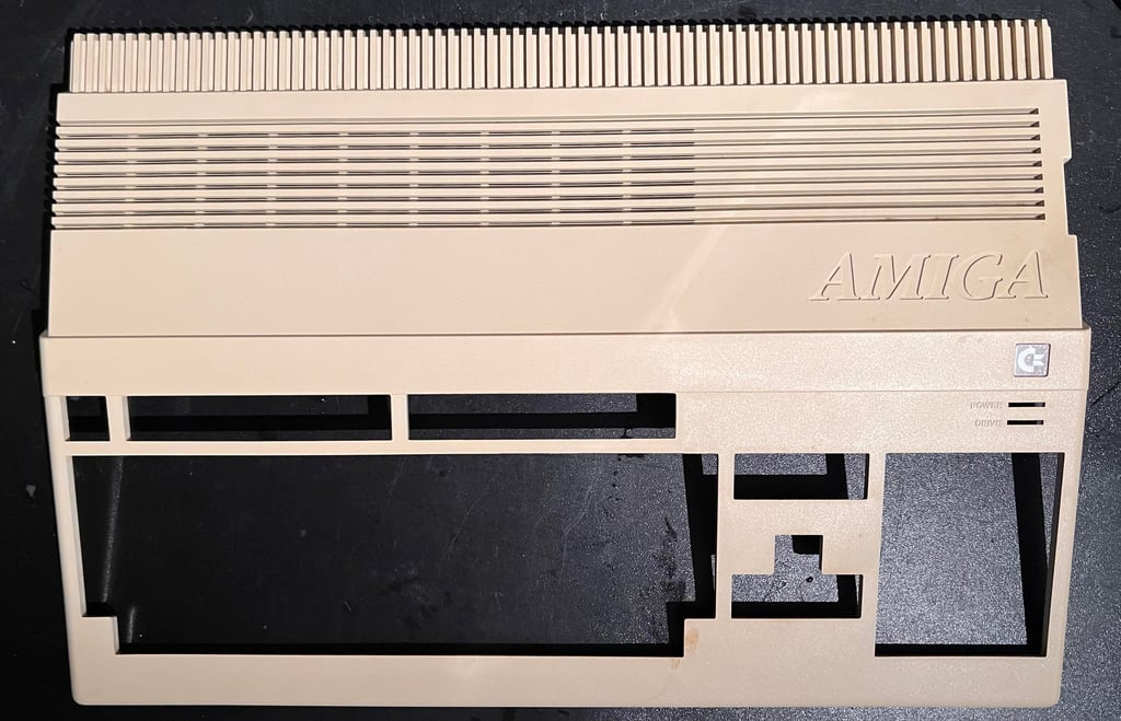
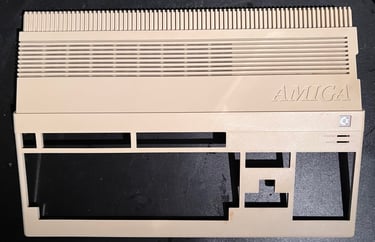
It is not too bad. Both top- and bottom cover are dirty and yellowed, but it is not something that can´t be fixed with cleaning and retrobrighting. Below are pictures of the covers before cleaning.
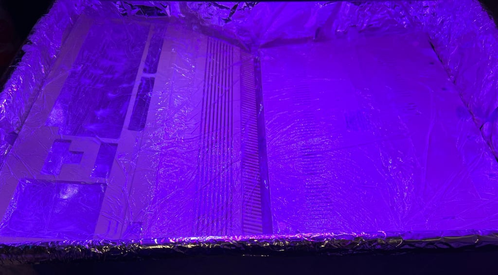
The covers are cleaned properly with mild soap water. Some of the stains are removed with isopropanol, but there are not many of them. Since the covers are slightly yellowed they are also retrobrighted. This is done by using 12 % hydroperoxide cream which is applied regularly during a 12 hours UV exposure.

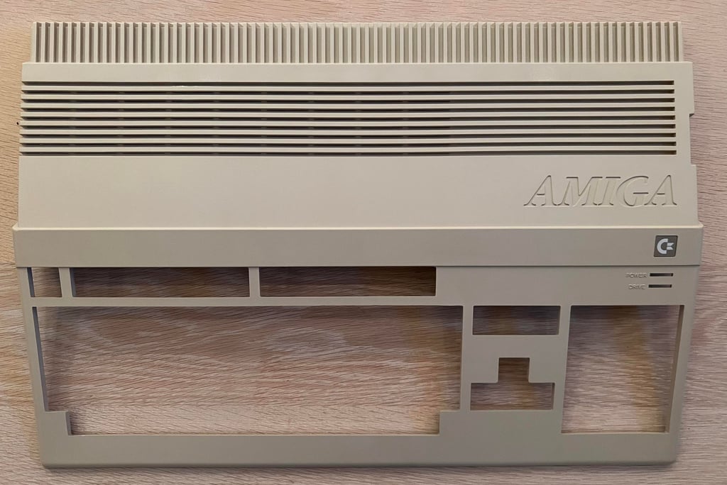
Result after retrobrighting is quite good. Most of the yellowing seems to be gone. Of course, it is not 100 % back to original colour, but it is way better than it was before refurbish. Note that the floppy eject button is also retrobrighted.


Mainboard
Visual inspection
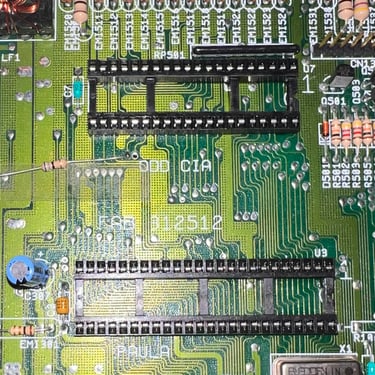
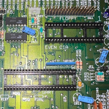
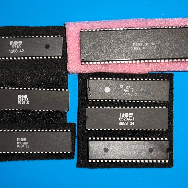
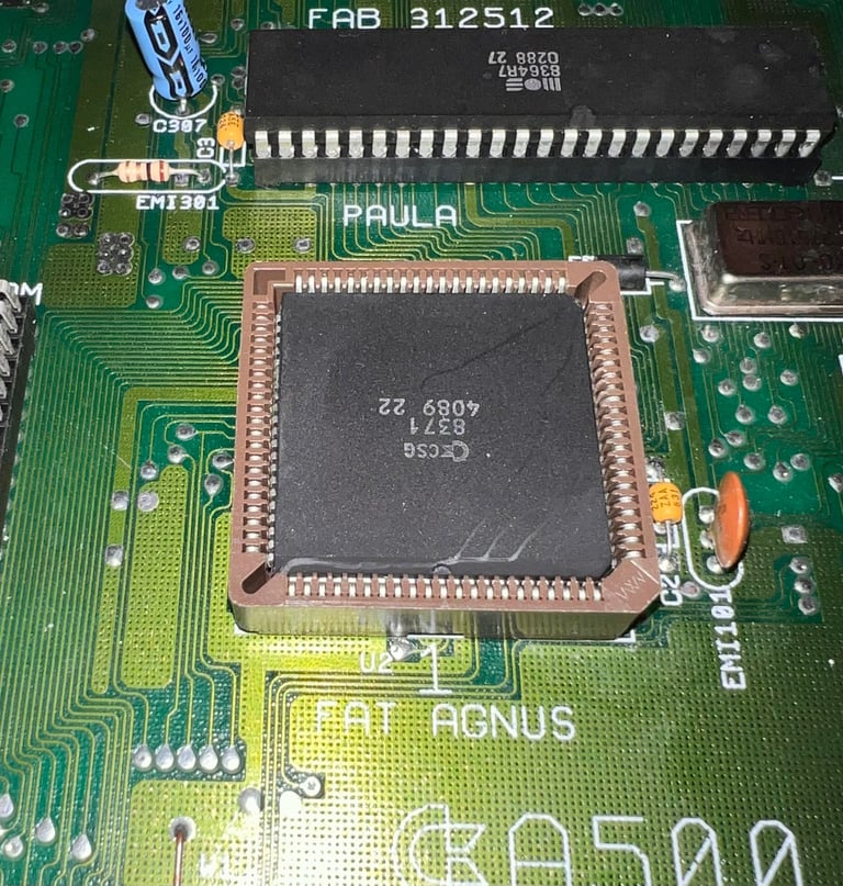
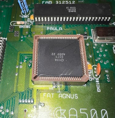
In the table below all the major custom IC found on the mainboard are listed. As can be seen from the table the custom MOS chips were produced during a long time interval. The oldest is the MOS 8367 (Paula) chip from week 02 in 1988. The youngest is the MOS 8520 (Odd CIA) from week 51 in 1990. Interestingly the MOS 8731 (Fat Agnus) is produced in week 40 in the year 1989. Note also that the keyboard controller IC (located on the keyboard PCB) is from week 47 in 1990.
So, what does this mean? Of course it could be that all these chips were installed at production time, but I doubt it. Instead my hypothesis is:
Keyboard malfunction - perhaps due to a short circuit(?): The odd CIA was changed sometime after late 1990. Perhaps in 1991. This chip is both from a different time period than the even CIA, and is also of a different make. The odd CIA is the I/O device enabling the keyboard to receive/transmit data. And the keyboard is probably from late 90 / early 91 since the keyboard controller IC is from week 47 in 1990. Perhaps the keyboard - the whole or the PCB - was changed at some point due to problems causing both the keyboard and then consequently the odd CIA to fail? A fault in the keyboard could cause the odd CIA to fail and vice versa.
The Fat Agnus was changed after a year or two after if was produced. Most of the chips are either early / mid 1988, so to install a Fat Agnus with a year code one year later sounds unlikely.
Intial testing
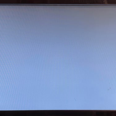
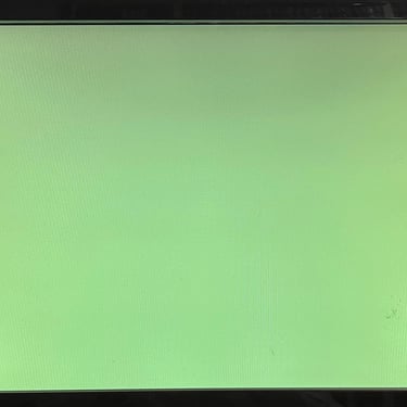
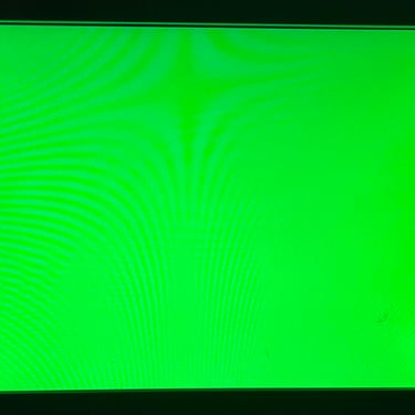
This machine is known be non-working. Or more precise, only working from time to time. Either booting up without any issues or just the “green screen of death”.
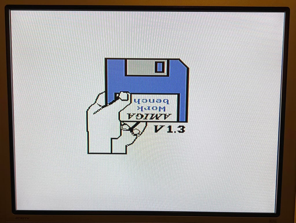
And it turns out be a very good description. At first I am very pleased that the machine boots up without any issues. But after a few power cycles it starts to behave very odd. Most of the time it starts with only a black screen, then sometimes a grey screen for a few seconds before turning yellow and finally the “green screen of death” several times. And between these test the “Kickstart 1.3” normal boot up-screen turns up. So there is obviously something wrong here…
Mainboard - repair
Cleaning the sockets and custom chips
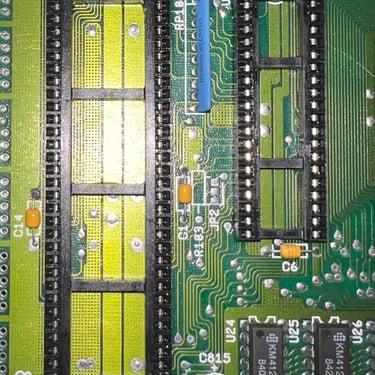
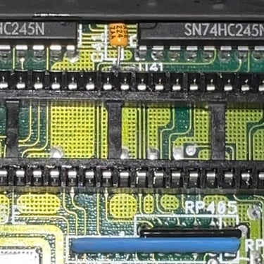
A very common fault on the Amiga 500 is either faulty sockets or oxidized pins on custom MOS chips. Therefore all the chips are lifted from the sockets, and all sockets and chips are cleaned properly with isopropanol (pins are cleaned with a glass fibre pen also).
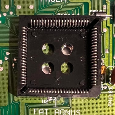
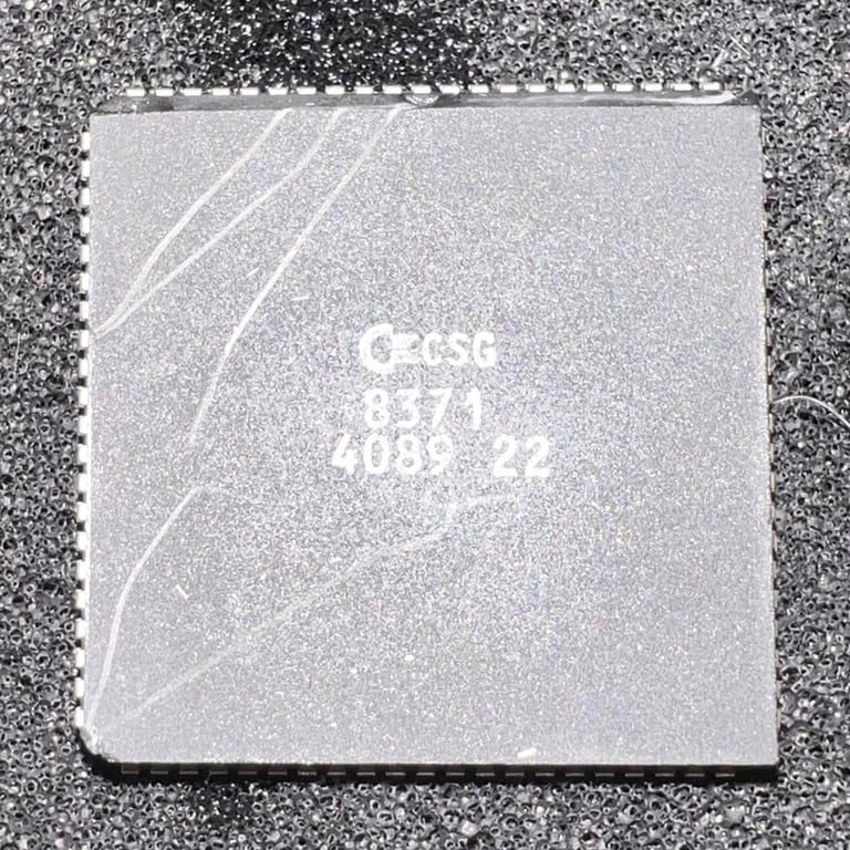
The MOS 8371 Fat Agnus chip is really “stuck”. There is a small bulge in the socket – could it be that this is the culprit? After some careful wiggling and lifting with a PLCC chip lifter and a sharp tool the Fat Agnus is loosened. One of the pins is heavily corroded. It is removed with isopropanol and a glass fibre pen, but I wonder if the oxidixation / corrosion is continuing inside the chip itself.
Below are some pictures after the cleaning. Note that there are some scratches on the Fat Agnus, but it is only cosmetic (from the PLCC tool).
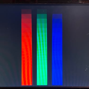
The result after cleaning is interesting. You can argue that it is worse, but I think it is better. Now the situation is more “stable”. It shows now only a grey/yellow/green screen.
While doing the cleaning and testing afterwards I notice something interesting. When the Fat Agnus is replaced in the cleaned socket the result is immediately a grey screen. After some sockets (when the electronic cleaning dries) it turns to yellow. And then after some minutes it is only a green screen. And finally after 15 minutes it is only a black screen. Is this the result of a bad socket and/or a bad Fat Agnus? Below are some pictures of the grey, yellow and green screen.
Replacing the Fat Agnus socket
Sockets in the Amiga are notorious for failing. And since the Fat Agnus appear to behave different either when the socket is pressed sideways or directly after cleaning with contact cleaner. It could be that the Fat Agnus is broken, but it is wise to change the socket anyway to rule that out.
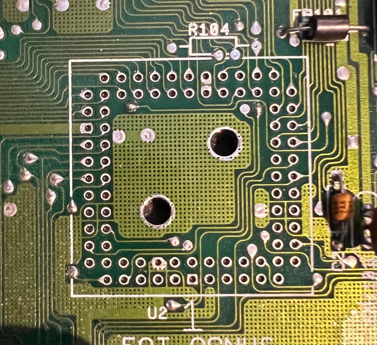
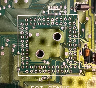
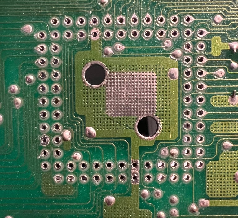
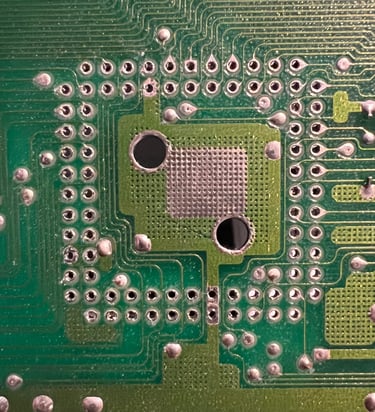
There are 84 pins on the PLCC socket. So to desolder this socket I highly recommend using a desoldering gun. In addition I also make sure that every pin is completely desoldered before trying to lift the PLCC socket off the board.
No traces or pads were damaged during desoldering. Also, every of the 84 pads are checked for connectivity.
Below are some pictures from the desoldering.
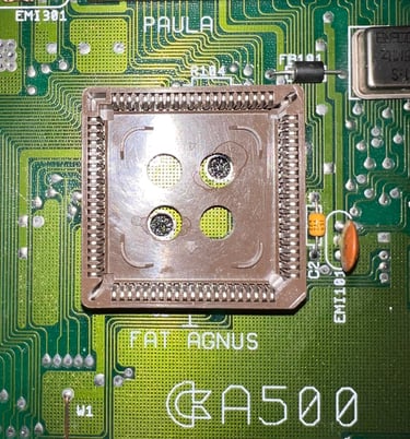
New PLCC socket is ordered from mouser. It´s a bit different colour than the original, but the quality is superior to the original. The new socket is soldered in place. Note that the PLCC socket needs to be positioned the correct way. A small arrow inside the socket points to pin #1. Below are some pictures with the new socket in place.

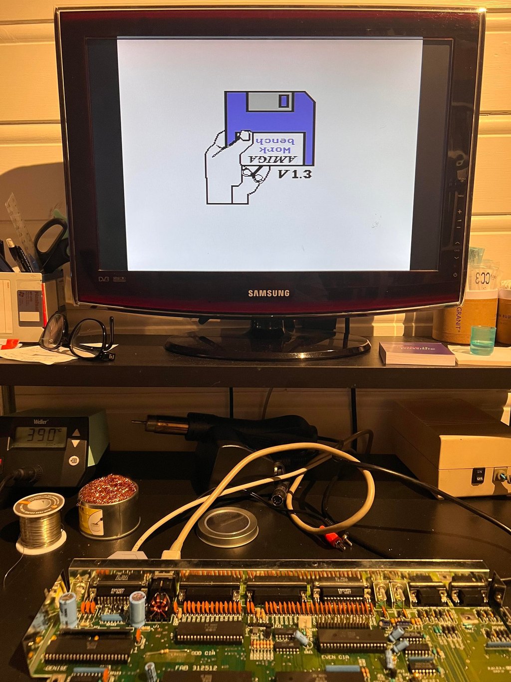
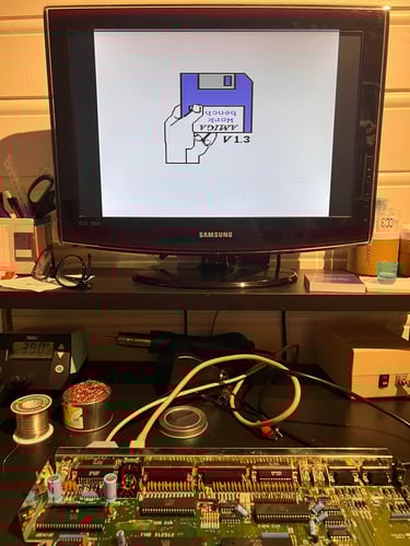
The result after replacing the PLCC socket is... a SUCCESS! When powering on the Amiga the classic screen appear immediately! I still need to test this further, but the PLCC socket was obviously bad.
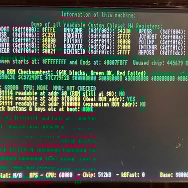
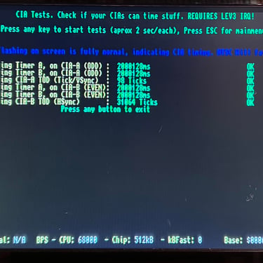
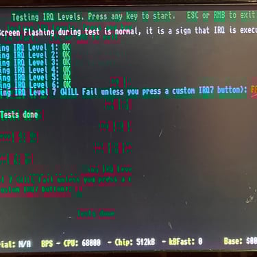
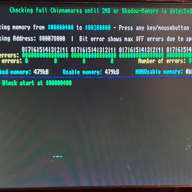
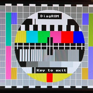
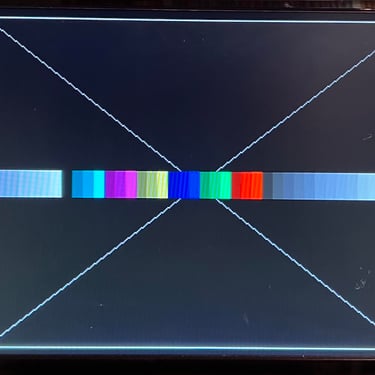
Initial testing - DiagROM
A very good tool for testing is the DiagROM chip. This chip replaces the Kickstart ROM and gives detailed test information when installed. With this chip installed all tests pass as far as I can see (the keyboard test is not done here). See pictures below. NOTE: Since this is a REV 5 mainboard a special EPROM adapter is required for the DiagROM to work.
Mainboard - refurbish
Checking the voltages
It is good practice to check that all voltages. For the Amiga to operate flawlessly it is crucial that all voltages are present and within acceptable tolerances.
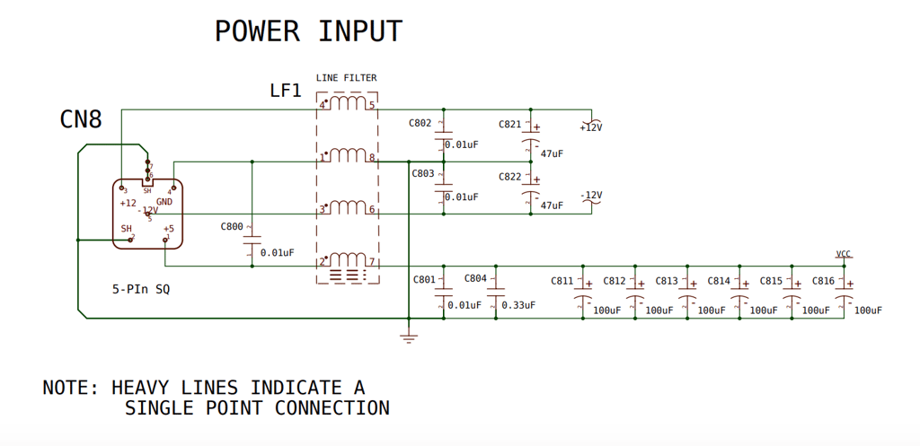
The Amiga 500 use both +5VDC and +/- 12VDC where the 5VDC is used to power internal components on the mainboard such as ICs, and the 12VDC is used to power peripherals such as internal/external disk drives. Below is a schematic from the power supply input (note that this schematics is from a REV 6 mainboard).
In the table below the measured voltages at different positions are listed. All voltages are within acceptable tolerances. Note that this table will also be updated after refurbishment is complete.
Replacing the electrolytic capacitors
The mainboard (Assy 312510/Artwork 312513 Rev 5) contains 16 electrolytic capacitors. It is not strictly necessary to replace these capacitors, but it is good practice while doing refurbishment. Why? Well, these capacitors are over 30+ years old and they will dry up eventually. Although many of these capacitors are used for decoupling and filtering a marginal capacitor can cause irregular faults on the Amiga.
Note: one pad was lost during desoldering C812. This happens from time to time unfortunately. The reason is that the ground plane on the Amiga 500 is massive, and in order to source sufficient heat to these solder points the temperature needs to be set high (about 400 Celcius). When the temperature is so high the pad can loose grip from the PCB. But even if the pad is lost there is no loss of continuity - no bodge wire is required.
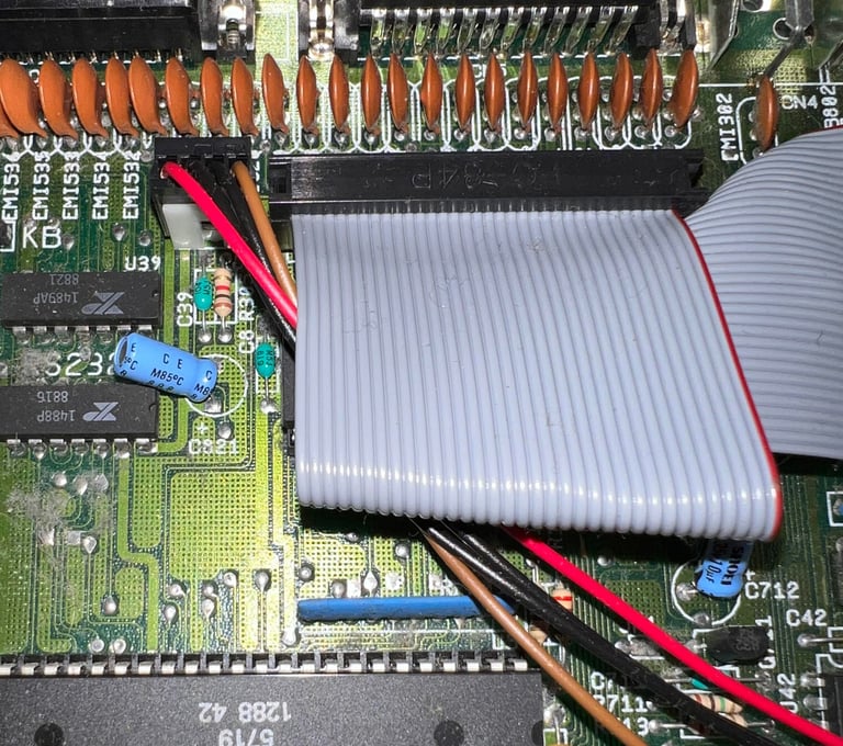
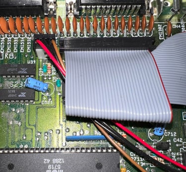
Below is a picture of the mainboard after replacing all the electrolytic capacitors.

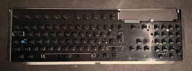
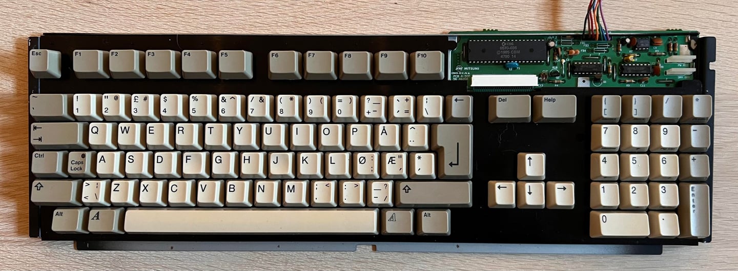
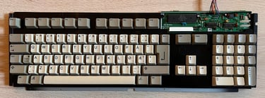
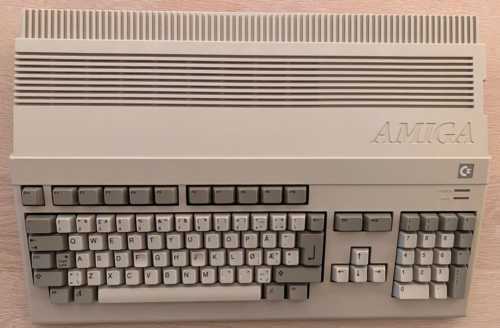
Keyboard
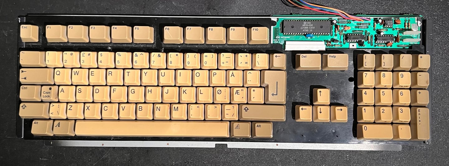
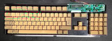
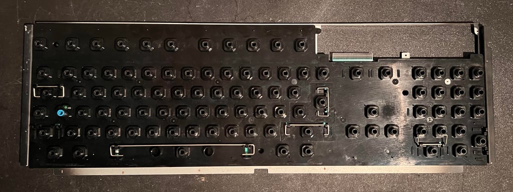
The keyboard is very dirty and yellowed, but appear to be in good condition otherwise. Also, this keyboard has the Norwegian layout with the "Æ", "Ø" and "Å" keys near the RETURN key area.
First, all the keycaps are removed with a keycap puller. It is highly recommended to use such a puller to reduce the risk of damaging the keys or the plungers.

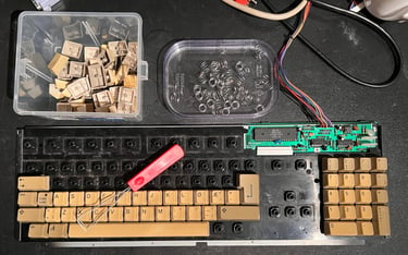
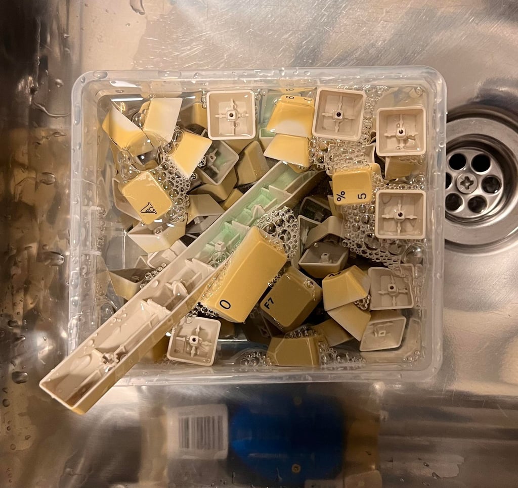
Note that there are two small more additional spring beneath the spacebar. So it is good practice to keep these in a separate bag to not mix it up with the others. All the keycaps are placed in a box of mild soap water for about 24 hours to dissolve all the dirt and grease.

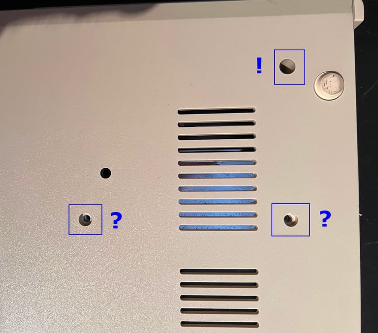
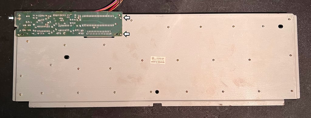
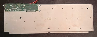
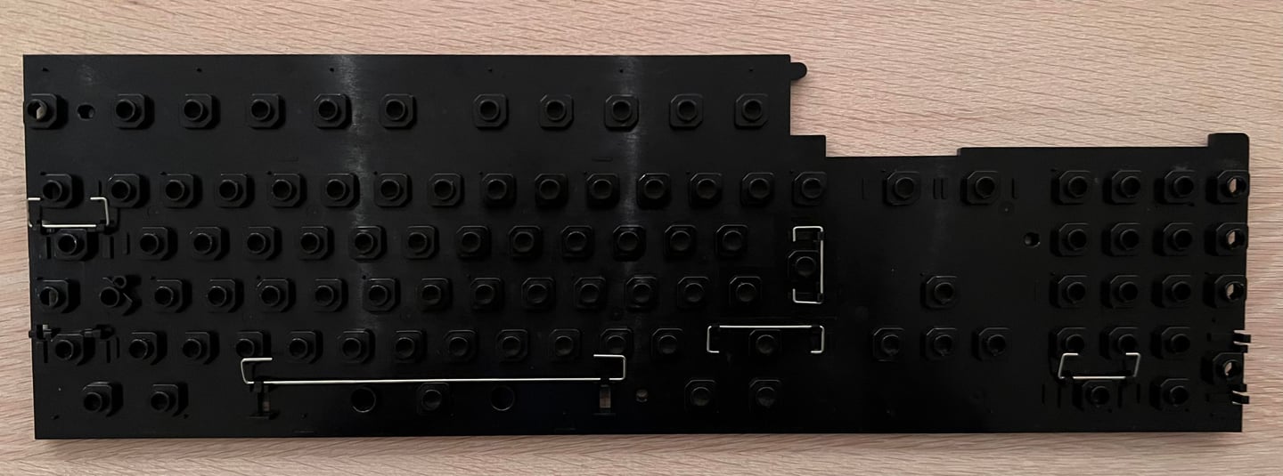
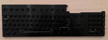
To completely disassemble the keyboard the backplate is removed. There are several screws which needs to be removed, and three of these need special attention. See picture below. These three screws holds the PCB to the metal backplate. Note that the two screws at the right side (see arrows) are above the plastic isolation, and the single to the left (see arrow) is beneath the plastic.
The plastic holder is washed properly with soap water and a paint brush. I forgot to take a picture of the membrane unfortunately, but it looks to be in good condition (Mitsumi A-500 A619B). The plastic looks good as new after cleaning. Note that there no metal bracket for the left SHIFT key. I actually thought that was missing, but it seems like this is from factory since I have seen this previously on other Amiga 500s.
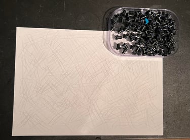
A clever trick to revive the key plungers is to carefully drag them over a clean sheet of paper. This will remove some of the grease and dust from the conductive rubber without damaging them. The key plungers are normally not as bad as the Commodore 64 plungers in this area, but it is good practice to revive them.

After all the plungers have been cleaned they are placed back in the plastic bracket and the keyboard is assembled (with the exception of the keycaps).
Oh my... the keys are.. so... yellowed. The pictures does not do it justice - it is even WORSE! I am not really sure I can return them to the original colour, but I will try hard. All the keycaps are placed in a plastic bag filled with hydroperoxide cream (12 %). They are in this bag for about a week, and from time to time I rotate the bag to make sure alle keycaps are completely soaked. For two days they are also exposed for UV light.

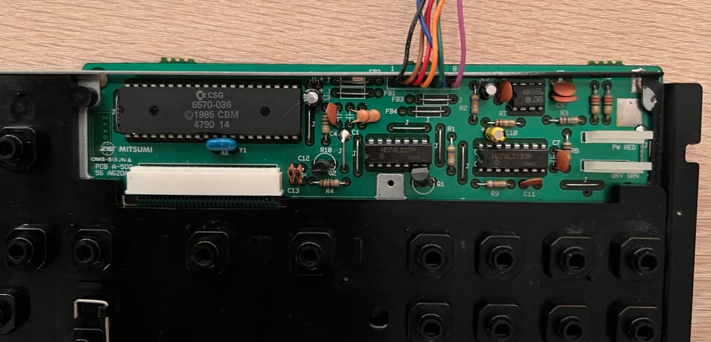
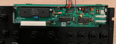
Replacing the electrolytic capacitors - keyboard PCB
There is a small PCB mounted on the keyboard with the MOS 6570-036 controller chip. On this Mitsumi A-500 A620A PCB there are three low profile electrolytic capacitors which are replaced: 1 x 10 uF [16V], 1 x 1 uF [50V] and 1 x 22uF [16V]. The PCB looks to be in very good condition also. No sign of corrosion or damage. Below is a picture of the keyboard with the new electrolytic capacitors in place, and the PCB mounted back on the keyboard.
Below is a picture of the final refurbished keyboard. I think it looks very good! Most of the yellowing is gone - it looks like new (!)
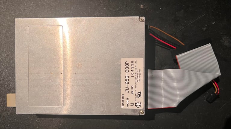
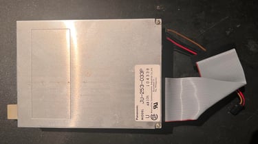
Disk drive
The internal disk drive is a model JU-235-033P from Matsushita (aka Panasonic). This drive is completely refurbished - please see this page for description.
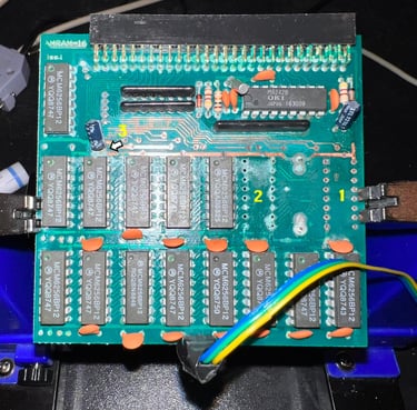
512 kB RAM expansion
The machine was shipped with a 512 kB RAM expansion card from Zydec (model AMRAM-16). This is probably an early model since it contains 16 RAM chips each able to store 256 x 1 bit which gives the total of 512 kB. According to the Amiga Hardware Database other versions of the AMRAM were equipped with 256x4 bit which probably were made later. Table below shows the ICs installed on this board.
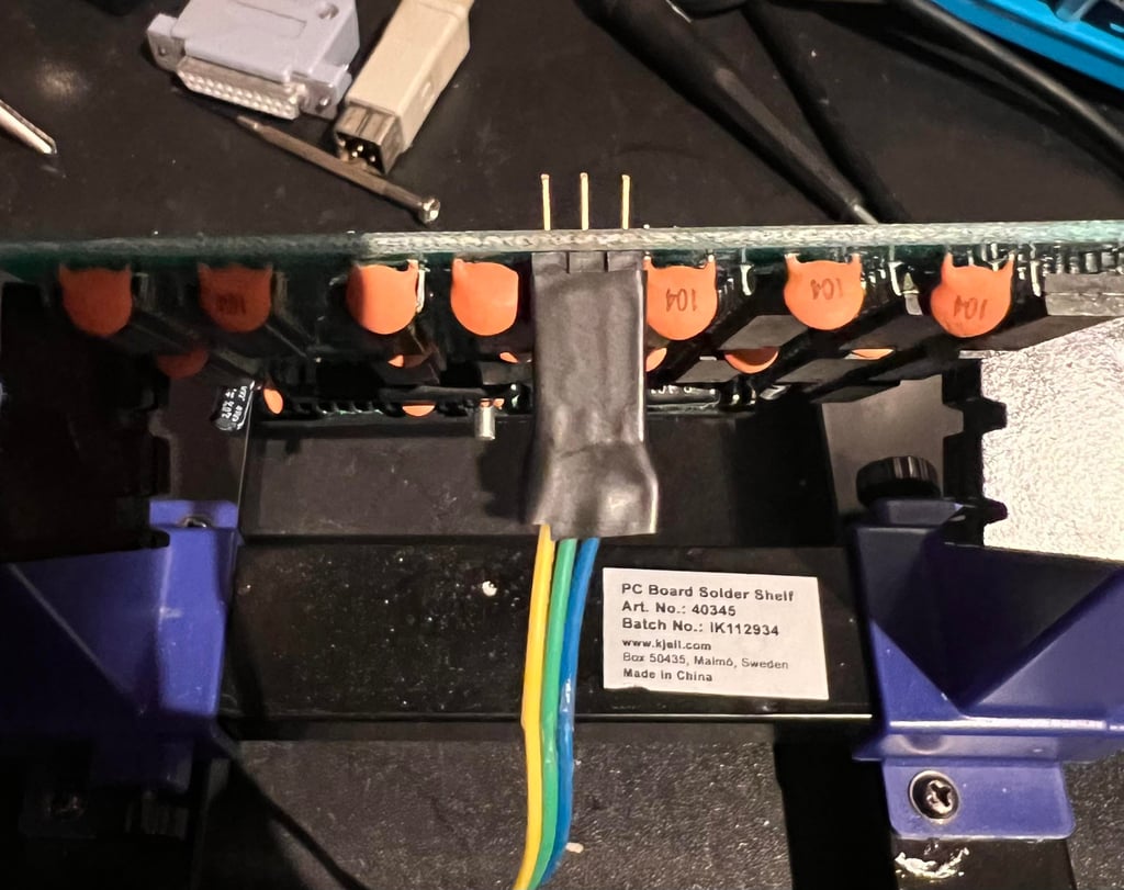
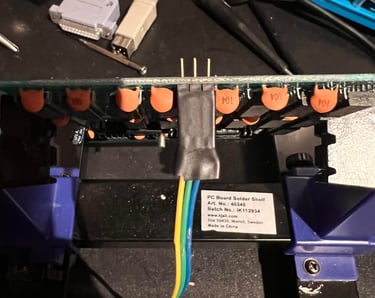
A quick check shows that the RAM expansion does not work. It is not detected at all in the Amiga 500. Checking the ON/OFF switch with a multimeter it turns out that this is not working, probably due to corrosion. The switch is desoldered and replaced with a three pin connectors and a wire (which can be connected to a switch later).
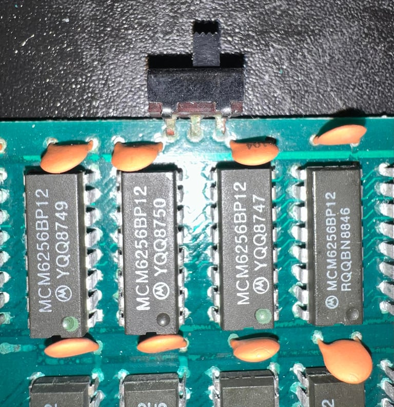


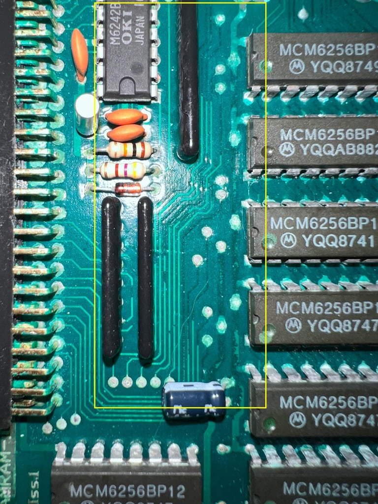
The switch problem is now solved, but the RAM expansion card does still not work. No additional RAM is detected (and I know the machine is able to detect other RAM expansion cards). Since the card is severely corroded is is not unlikely that one or more traces or vias have broken. The boxed area in the pictures below appears to be a potential candidate for broken traces.

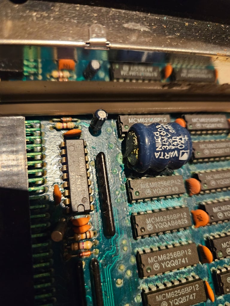
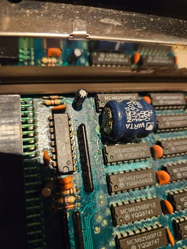
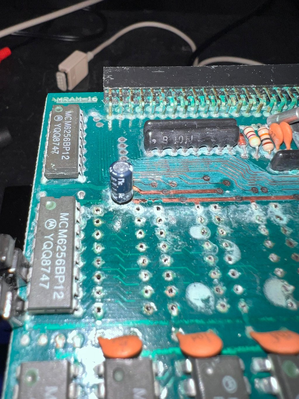
First the battery is removed and the area cleaned with some white vinegar on a Q-tip. Since the battery leakage is alkaline the acid in the vinegar will neutralize the area. But the area also needs to be cleaned properly afterwards with distilled water and isopropanol to prevent further damager. As can be seen from the picture below there are dark areas on the PCB traces. So chances are that the leakage has caused corrosion which could lead to broken traces...

From the table below we can assume that the RAM expansion card was manufactured some time after week 25 in 1988 - perhaps in the middle of summer of 88?Unfortunately, but not at all uncommon, the card contains a leaking VARTA battery. The leakage has caused severe discolouration, oxidation and corrosion. It is likely that corrosion has eaten up some of the copper traces.
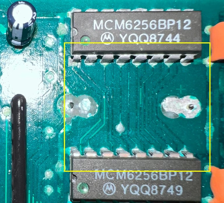

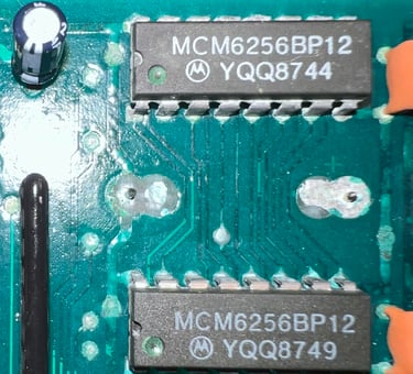
Two of the RAM chips are desoldered to better access the area. Diluted white vinegar is used first to dissolve the corrosion. The top solder mask is scraped off using a combination of a fine thin screwdriver and glass fibre pen to access the copper. Below is a picture from the process. Notice the difference between area "1" and "2" where the RAM chips were. Area "1" is now cleaned and "2" is not yet cleaned. Also notice that the oxidation is also around other components such as the capacitors. The area "3" could be assumed to be a capacitor leaking, but I think this is not the case. I think this is due to the battery leakage.

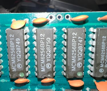
After cleaning the area I am able to check connectivity. With the multimeter I test the traces in the area, but the result is that the traces and pads/vias seems to be ok. But... one of the two RAM chips are not working (I use an A501 RAM expansion card with a socket to test). To make sure all the other RAM chips are ok - and that the area beneath the RAM chips is not too bad I decide to desolder and test all the chips.
During the desoldering process I notice that the area beneath the RAM chips is quite oxidized (and somewhat corroded). See picture below.

It turns out that 7 (!) of 16 RAM chips are broken or marginal! That is not good... I don´t think this damage is due to static electricity (or some kind of over voltage in general), but that corrosion has entered inside the chips and broken the hair thin wires inside.
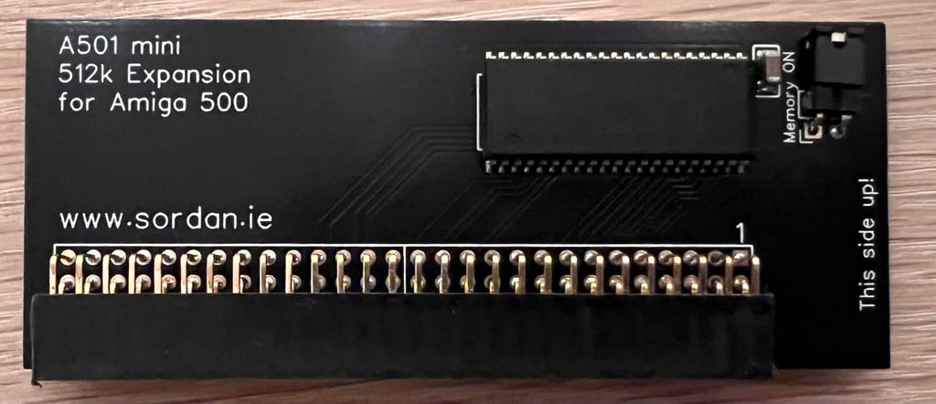
At this point I think it´s better to purchase a new modern RAM expansion replacement card. It´s not impossible to repair this card, but with seven non-working RAM chip it will be more expensive to buy new individual old replacement chips instead of a new modern "all-in-one" card. So a new 512 kB RAM card is ordered from Sordan´s webshop.
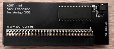
The new "A501 mini 512k expansion for the Amiga 500" delivered by Sordan is shown below. This is way better than the old corroded RAM expansion (!)
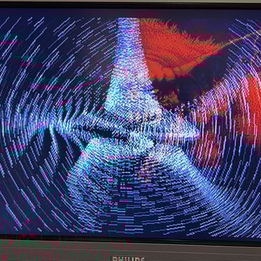
Testing
Now it is time for testing the whole machine. All parts such as keyboard, RAM expansion, keyboard and disk drive have been tested in isolation, but now I will try to test "everything". How? Well, I basically to this in two stages:
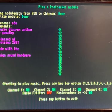
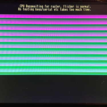
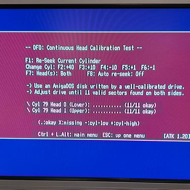
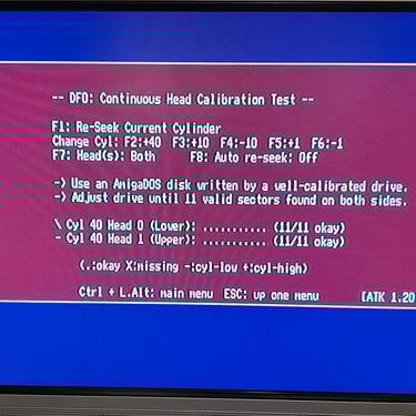
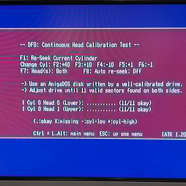
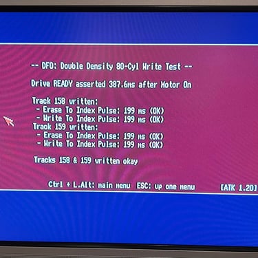
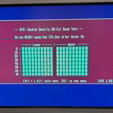
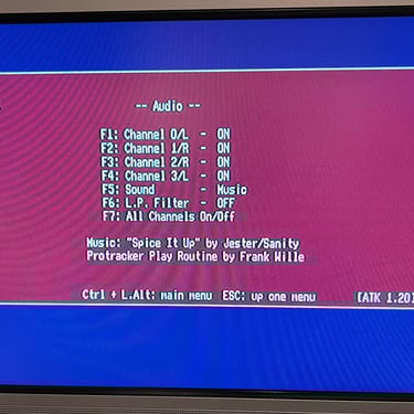
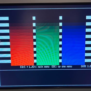
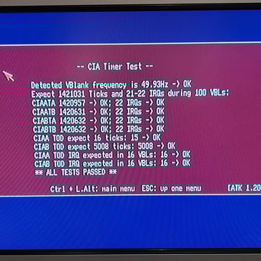
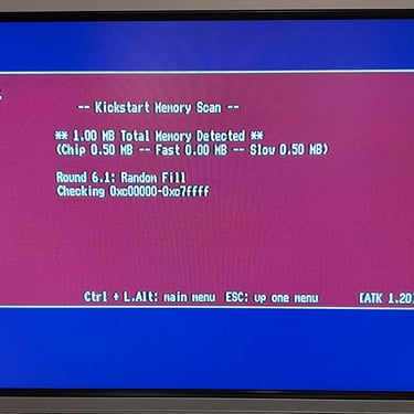
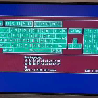
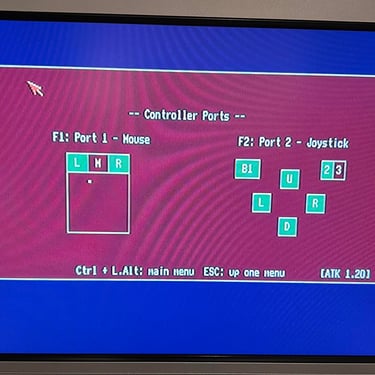
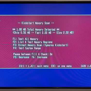
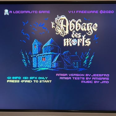
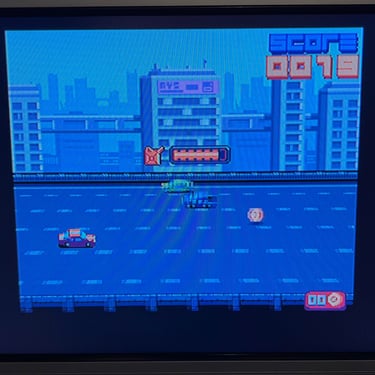
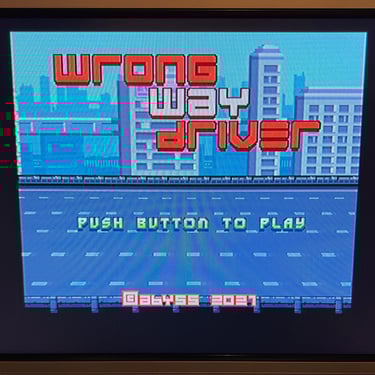
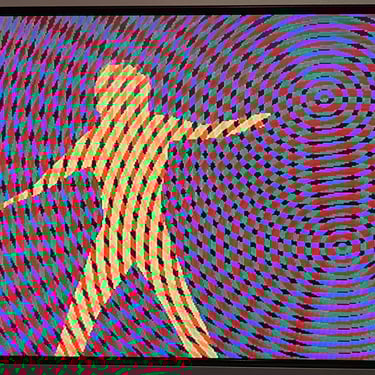
Formal testing with the Amiga Test Kit 1.20 (ATK). This will test most of the basic parts such as memory, floppy drive, video, audio, CIA, mouse, joystick and keyboard.
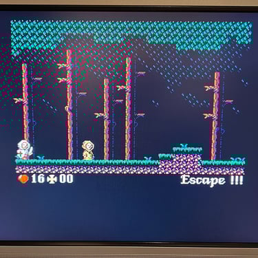
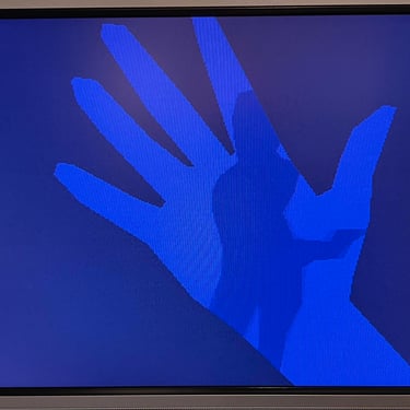
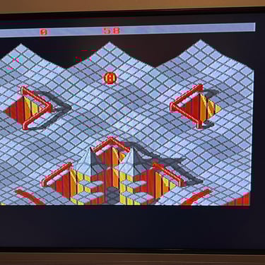
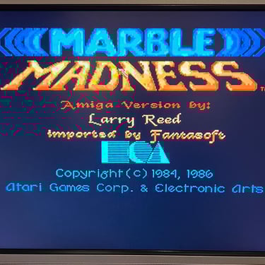
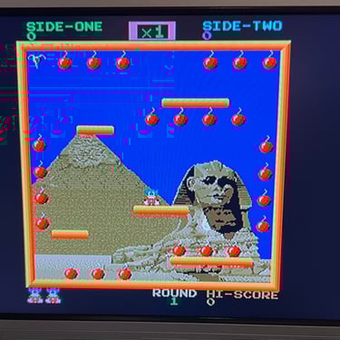
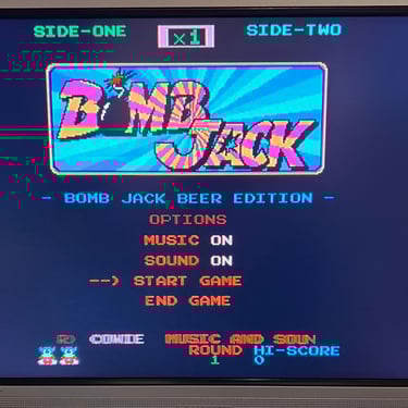
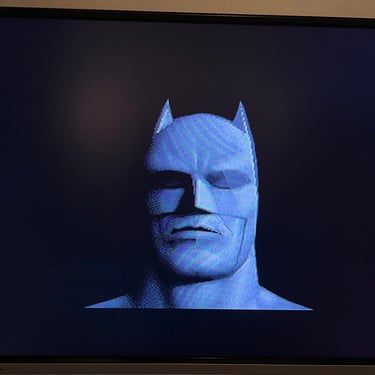
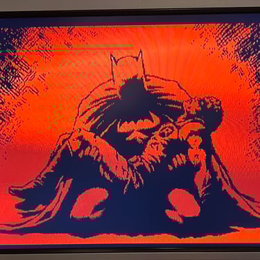
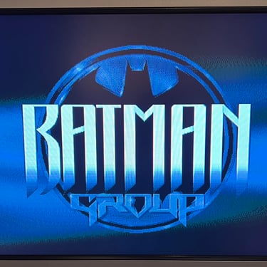
"Real usage" testing. I will basically use the machine playing games, watching and listening to demos and use the machine in regulator operation. This will detect flaws not easily detected with the ATK 1.20.
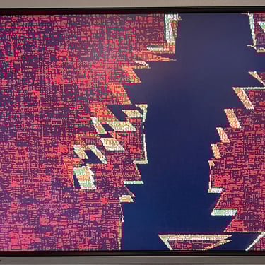
Below is a gallery from the final testing.


Final result
"A picture worth a thousand words"
Below is a collection of the final result from the refurbishment of this Amiga 500. Hope you like it! Click to enlarge!


Banner picture credits: Ajne01