
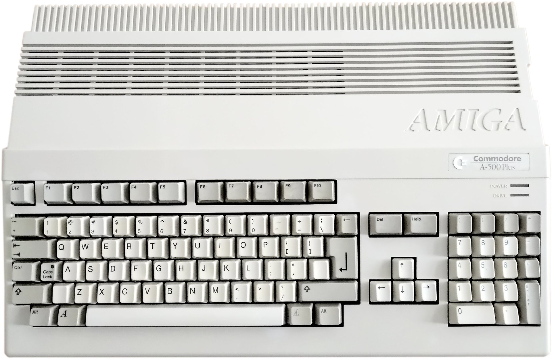
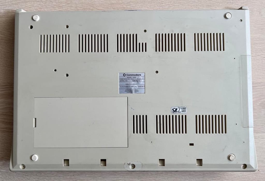
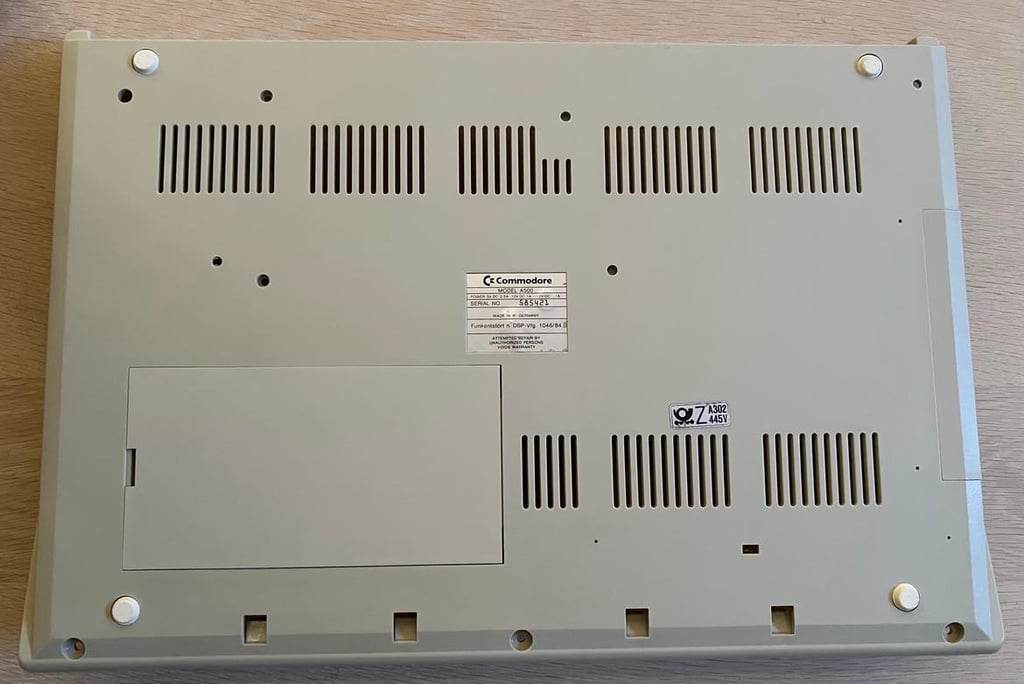
Amiga 500
Ser. No. 585421
Assy 312510
Artwork 312513 REV 6A
Starting point
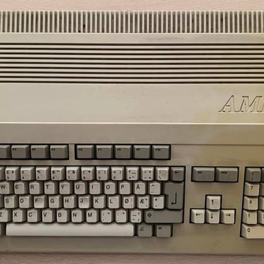
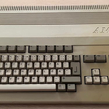
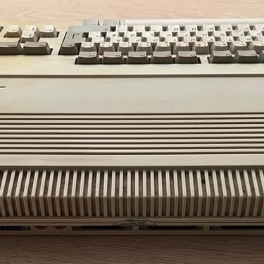
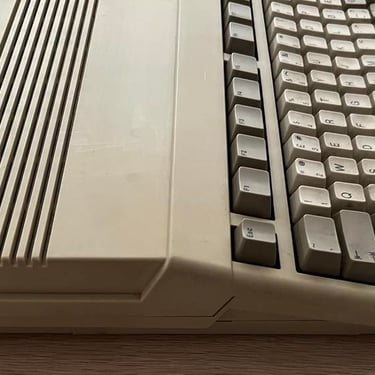
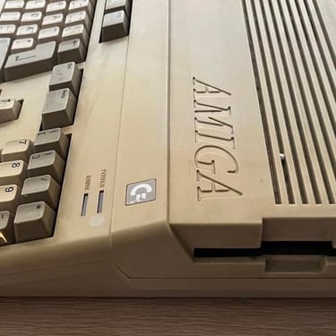
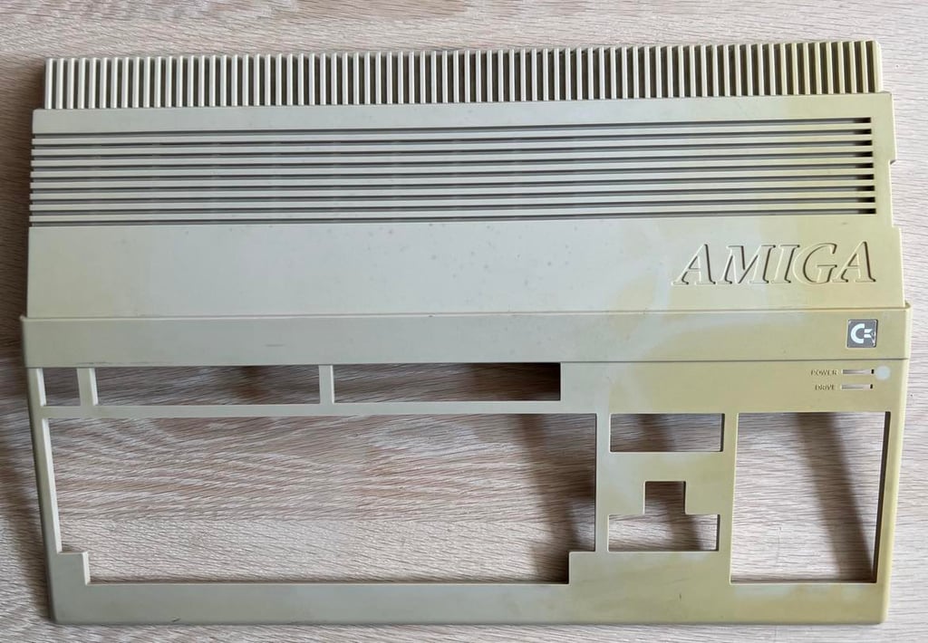
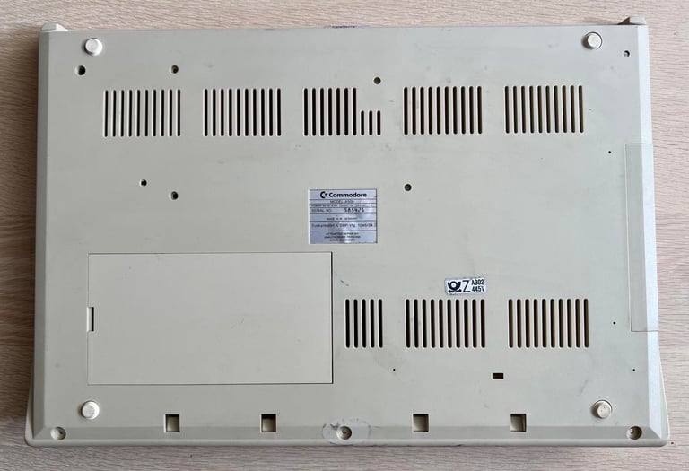
From the outside this Amiga 500 looks not too bad. Yes, it is dirty and partly yellowed. But otherwise I think it looks quite ok from an exterior point of view. Pictures below show the outside of the machine before refurbishment.

A do a quick test of the machine by connecting a known good power supply (PSU) and to a working TV set. On power on I first hear some quite disturbing sounds from the disk drive. Sounds like gears are rotating in sand or something... The disk drive needs a good cleaning at least! I will not test the drive further before some initial cleaning.
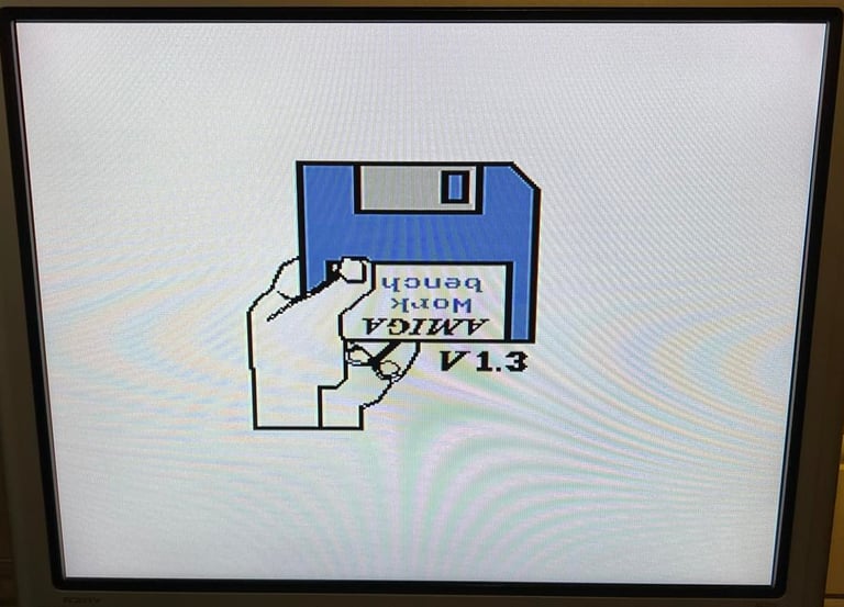
There is a picture on the screen. That is good, but the picture is not good. It´s flickering - not analog flickering, but something that looks like a digital issue to me. This machine needs repair! Video link below show the video output before refurbishment.
Refurbishment plan
To refurbish this Amiga 500 the plan is to do this trough the following steps (some of them in parallell):
- Clean and restore the keyboard
- Clean and remove stains from the exterior top- and bottom cover/chasis
- Refurbish the main board (cleaning, checking, repairing, replacing capacitors etc.)
- Verify operation by testing
Updated: This refurbishment plan will be abandoned in its current state. Instead of doing a complete refurbishment of the whole machine, the machine will be used as a test machine / spare parts machine. Why? Although it is possible to repair this machine (which is actually done) I think that the amount of work to do a complete refurbish is too much. Instead, I find it better to use this machine as test machine / spare parts.
Exterior casing
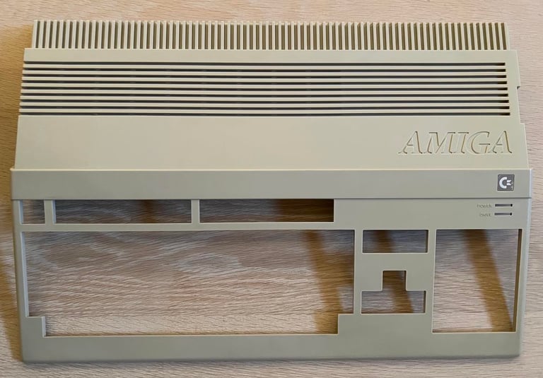
The top- and bottom cover is washed with some luke warm soap water, dried and then put outside in the sunlight (sunbrighting). I do not expect the sunbrighting process to remove all of the yellowing, but I think it can help a great deal. The casing is left outside in direct sunlight for several days (with some pauses in between - since it is rarely sunny for several consecutive days in Stavanger.
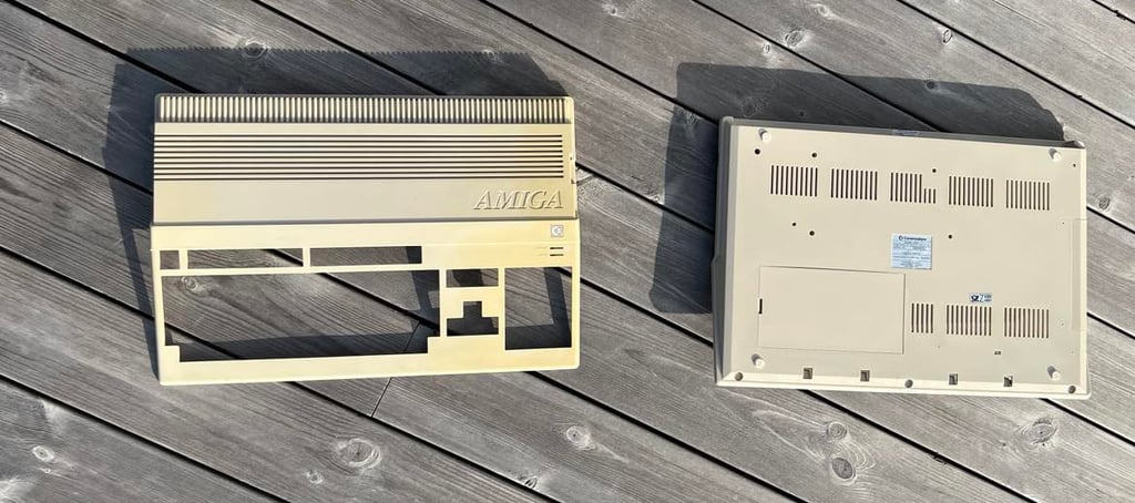
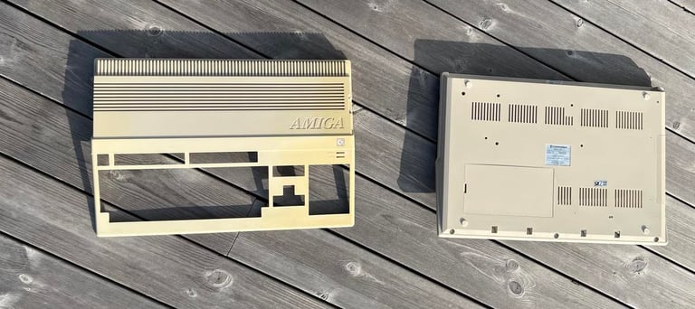
Both the top- and bottom cover is quite dirty. And the top cover is severely yellowed at the right hand side.

The result after sunbrighting is quite good. Not all of the yellowing is gone, but it is way better.


Keyboard
This Mitsumi keyboard need some serious cleaning. But, I also noticed during working on the mainboard and disk drive that there is something wrong with this keyboard:
The floppy LED does not work unless I press it down with my finger (Video)
The CTRL button doesn´t work - so no way to reset the A500 with CTRL-Amiga-Amiga keys (Video)
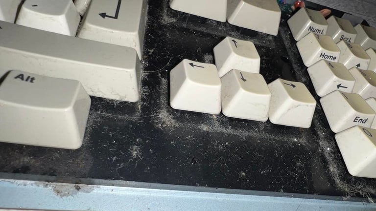
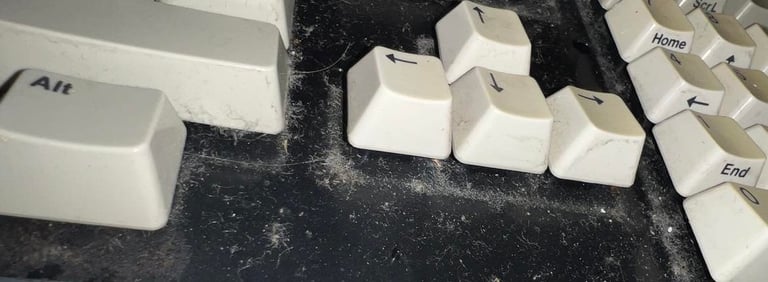
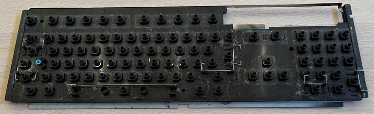
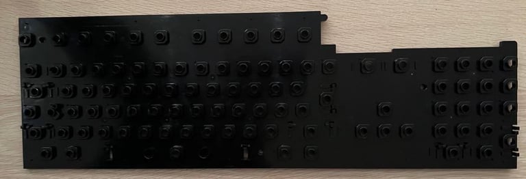
I need to fix these issues, but first I will clean the keyboard. The keyboard seems to be mechanical intact, but it is full of dirt and dust.

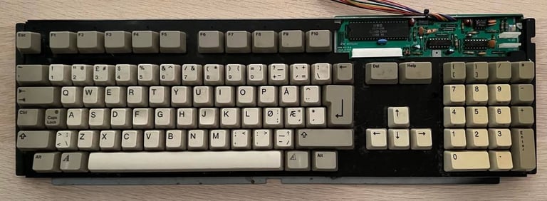
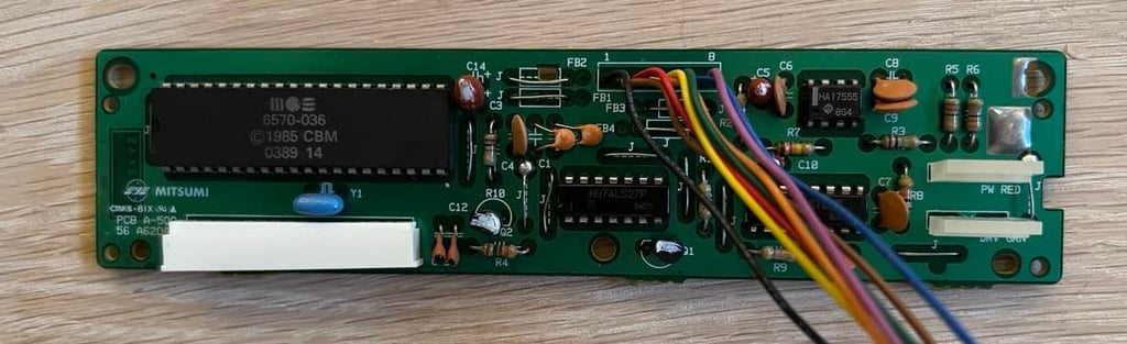
It may not looks so dirty from above, but with closer inspection I see how much dirt there is.
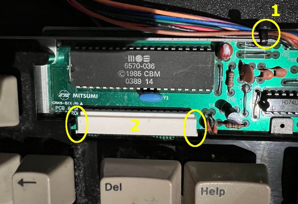
First thing to do is to remove the little PCB in the top right corner of the keybaord. This is done by first cutting the small cable tie (marked "1") and pushing the outer part of the wire connector down towards the keys (marked "2").

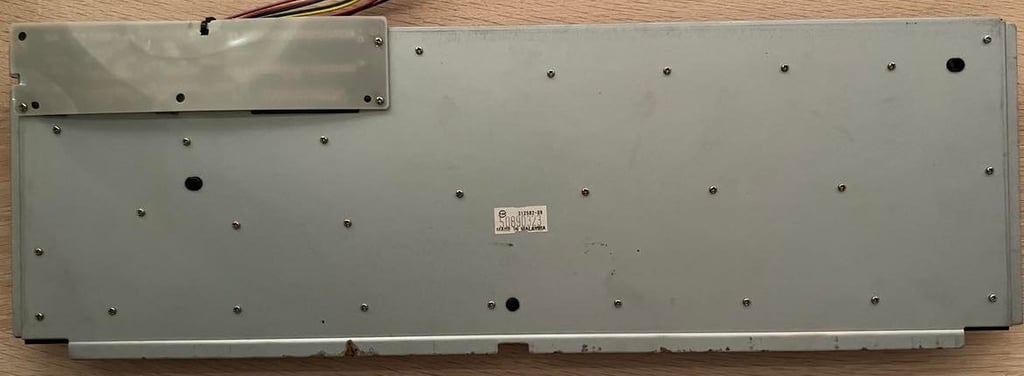
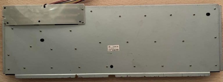
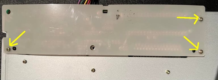
Next is to remove the plastic shielding fastened by the three screws at the backside of the keyboard. Note that these screws are a little bit longer than the rest of forty millions screws on the backside. So a good advice is to keep these three screws separately. With the plastic shield out of the way the PCB is exposed. Then I remove the last special screw holding the PCB (again, keep good track of these screws).

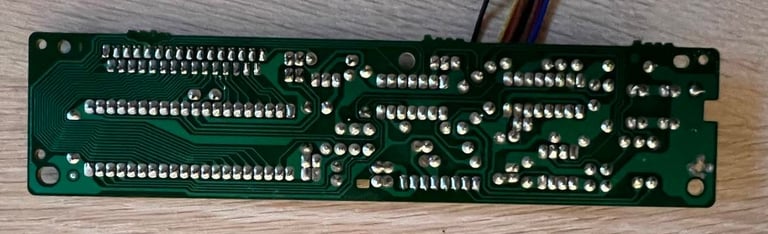
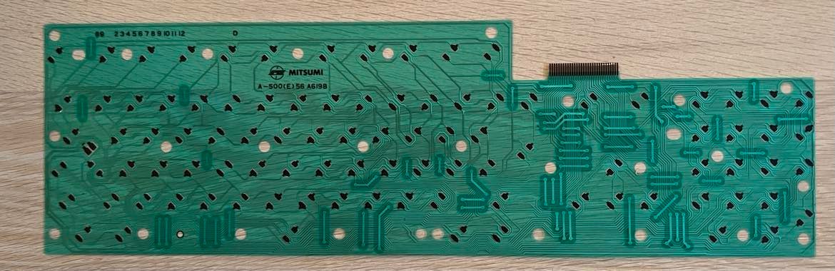
Then I carefully wiggle the PCB out of the keyboard. It´s important to keep an eye on the thin band cable which is in the connector - it should come loose but it´s wise to be careful so it don´t break. When the PCB is out I clean this properly: first with mild soap and water (yes, you heard me!) and then I rinse the PCB with plenty of isopropanol. The PCB looks as new.


All keycaps are removed with a keycap puller. All the keyscaps are placed in a box filled with water and mild dishwasher soap overnight. Notice that the springs used for the spacebar (there are three springs) are different than the rest of the keys. So I place these springs in a different bag to avoid mixing them. With the keycaps removed I see how dirty the keyboard really is:
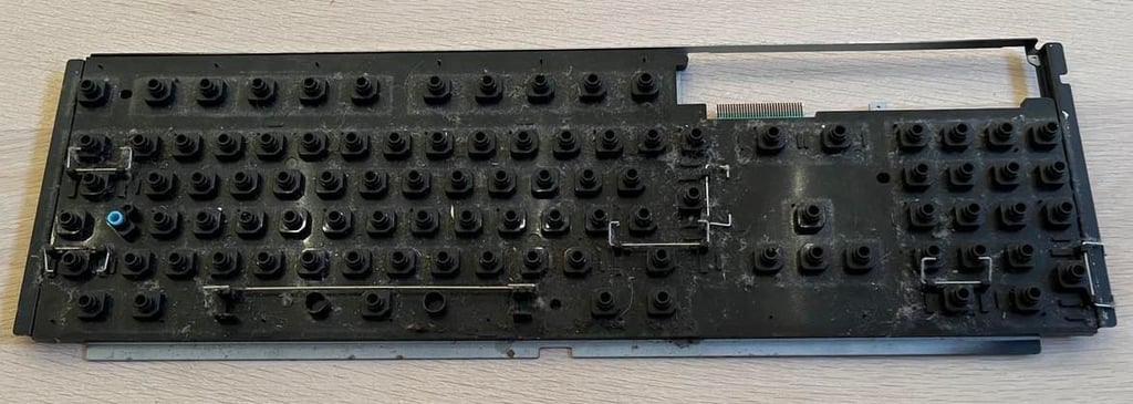
Next, all the (very) small machine screws are removed from the back of the keyboard. This will reveal the folio/membrane PCB used in the keyboard. I was expecting some grease around the CTRL key area - but there are only some grease in the areas nearby. And I don´t really think this grease would effect the sensing of the CTRL key.

I clean the keyboard membrane gently with isopropanol. Note that it is important to not clean this membrane too hard to make sure the key pads are not broken.

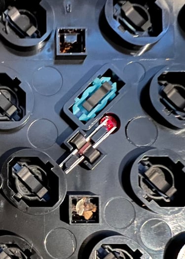
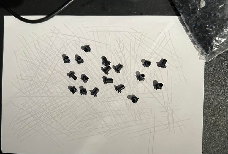
All the key plungers are emptied from the plastic chassis to be "revived" by gently rubbing them over a clean piece of paper. This is a a nice little trick I use to make sure that all the keys react when being pushed down on the keyboard. Notice also that the LED used in the CAPS-LOCK is easy to remove - which it should when the plastic chassis is cleaned.

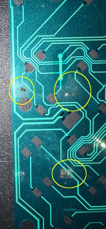
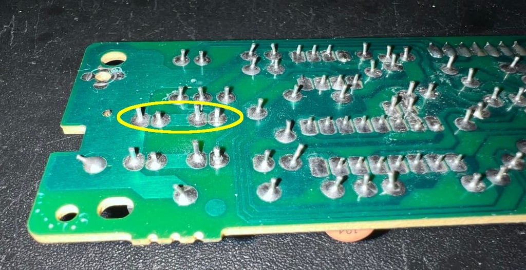
It´s not so easy to see from the picture below, but it seems like one of the solder points connecting the "DRIVE" LED is loose. I reflow all of the four points shown in the circled area.

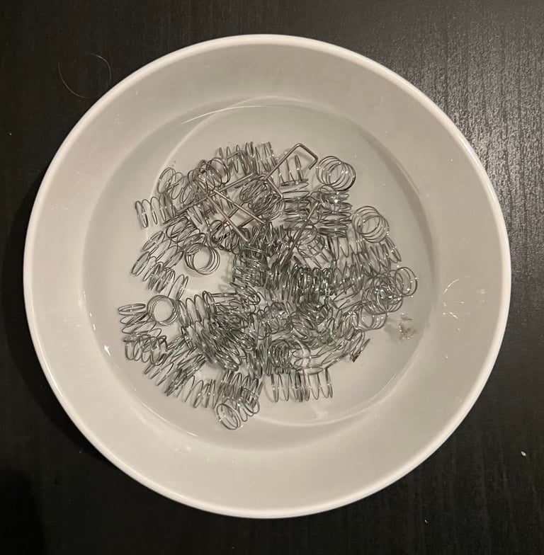
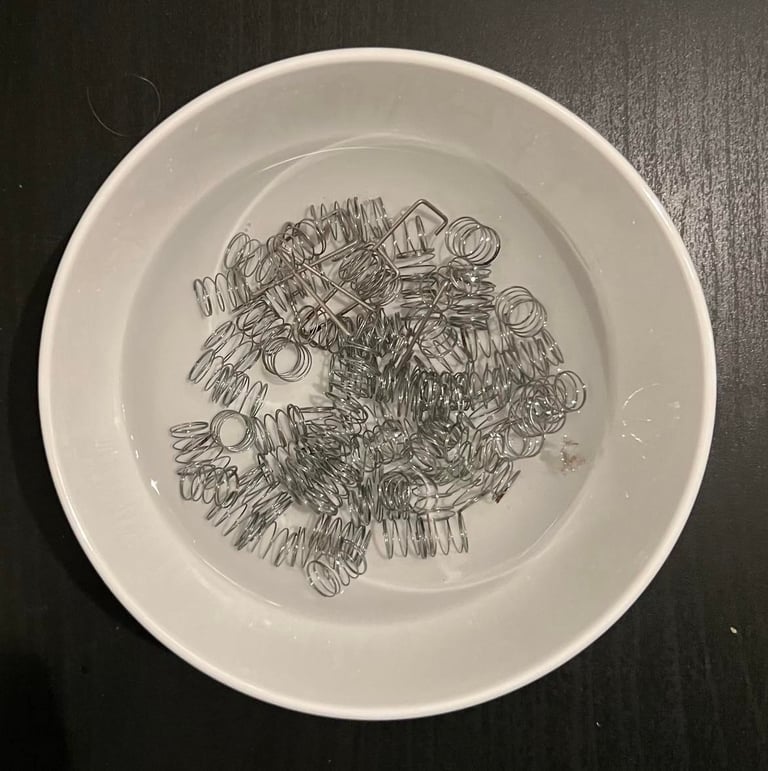
All the springs are placed in a bowl of vinegar for an hour. The springs are not corroded, but I think it is good practice to do this to make sure there are not any small "hard to see" corrosion. It is important to clean the springs afterwards with isopropanol to make sure the vinegar is not destroying them later since it is an acid.
The plastic cover looks almost new after cleaning.

After the cleaning the keyboard is partly re-assembled to check if it now works. It turns out that the "Drive" LED is no working fine, but the CTRL key still doesn´t work. I use a multimeter to check that the pads are ok - which they are. But there seems to be a broken trace between one of the CTRL pads to the end connector on the keyboard membrane. I´ve seen this being repaired before using things such as conductive paint. But... I really don´t like this kind of repair. The membrane is thin and flexible, and even if the membrane is "stuck" in between the plastic cover and metal plate I think that it will be exposed to movement. Think about yourself hammering the keys - the membrane will move and I´m afraid that such repair will fail eventually.
So I decide that the best thing to do is to order a new keyboard membrane. They are a bit more expensive, but I think that it´s worth it: we want our Amiga 500 to work as long as possible!
Main board
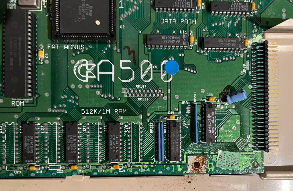
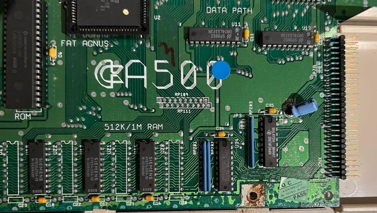
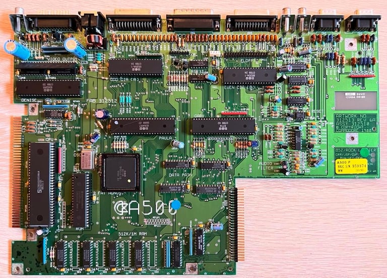
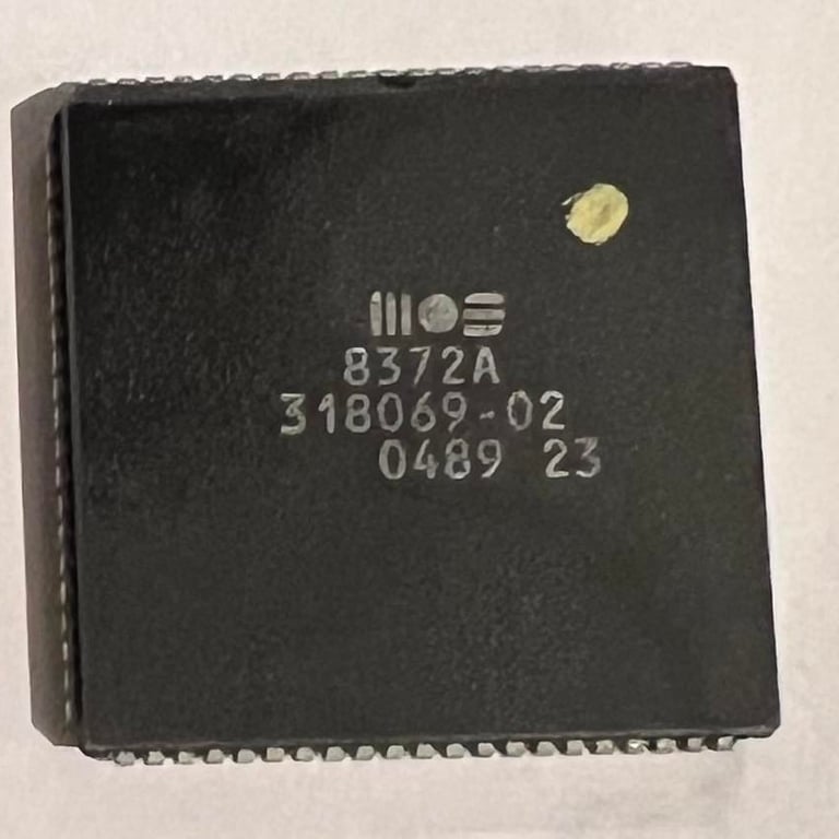
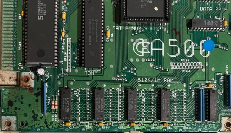
"Rock Lobster in da house!" - Revision of this main board it the Assy 312510 / Artwork No. 312513 REV 6A.
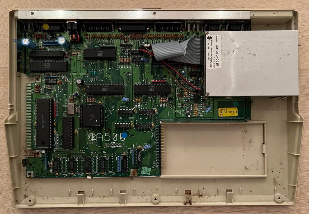
The first thing I do is a visual inspection of the main board. And I notice the following:
The PCB is very dirty. The picture below does not show it very well, but I see a lot of dust and grease. I need to clean the main board.
I can´t see any immediate leakage from any electrolytic capacitors. That said, I will probably replace these as a measure to increase the probability of a "long life".
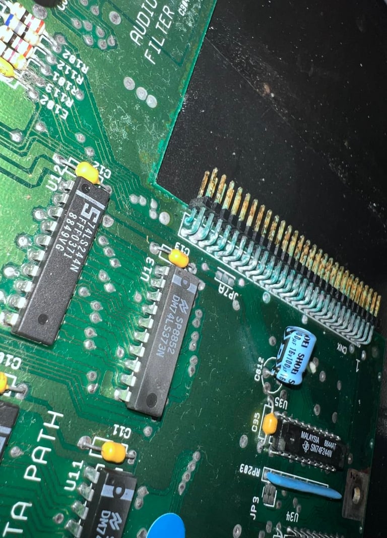
There are some areas which have some corrosion. The area seems to be around the edges of the PCB at the bottom and left side. This needs to be checked and repaired.
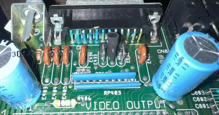
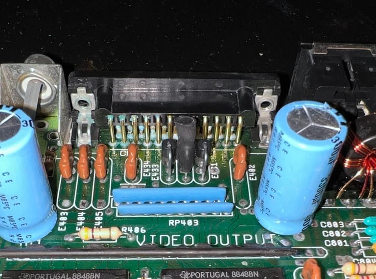
The pins on the RGB video connector have some weird colors (?) or corrosion (?).
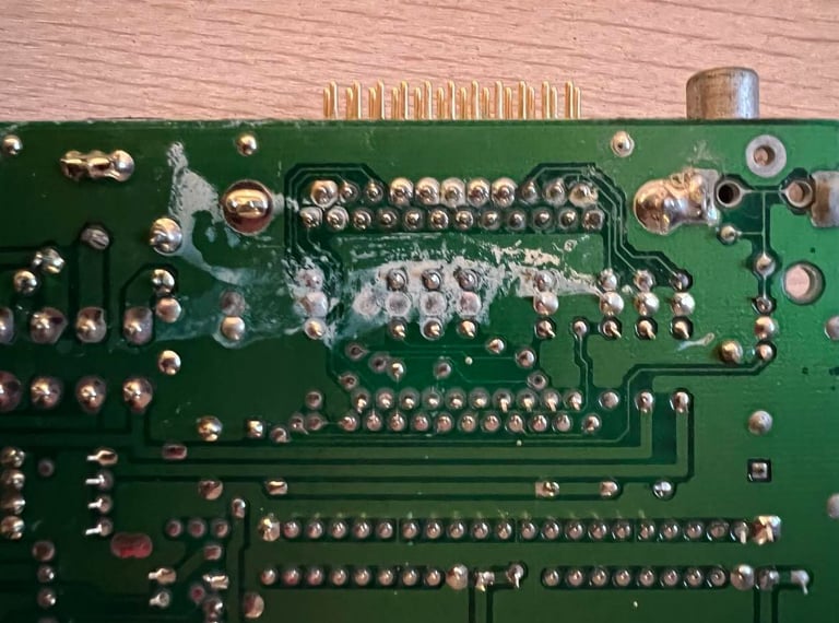
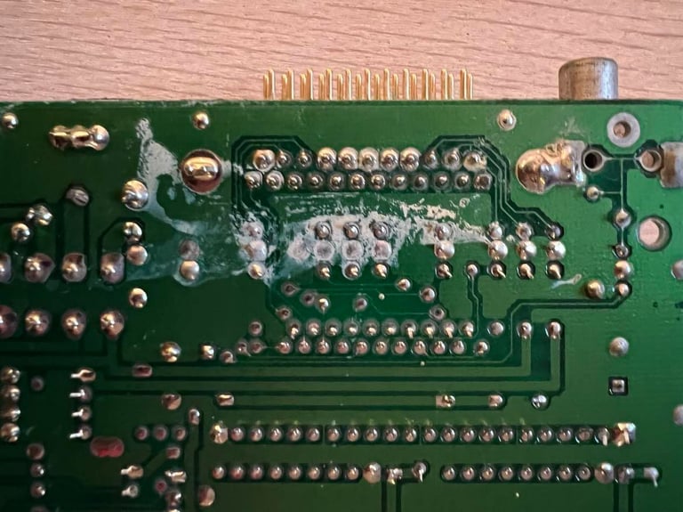
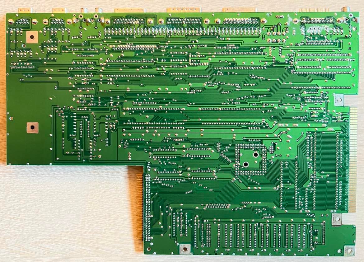
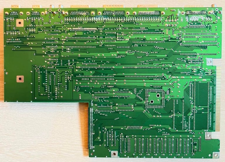
Backside of the PCB looks ok except for an area around the RGB video connector. It doesn´t look like normal corrosion, but more like a chemical reaction? Could this also be related to the odd colors seen on the RGB connector on the top side of the PCB?
All chips looks to be in-place and not damaged. That said, it doesn´t mean that they work or that all pins have good connections, but they are not mechanically broken at least.
Below are some pictures showing some of the points above.
There are some corrosion around the bottom and left edges of the main board.

Also the expansion port have something that looks like corrosion to me.
Here is the RGB video port pins and the backside of the PCB around the connector.
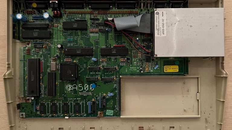
First thing to do is to clean the main board. I know that this might seem like crazy to some people, but I clean the main board with mild soap water and a paint brush first. Then I apply a good amount of isopropanol to make sure all the water residue vaporize. In addition I also use some vinegar on a Q-tip around the most corroded areas (on the front of the PCB). This cleaning will not fix anything, but I think the repair work will be more enjoyable. Below are pictures of the cleaned main board - before repair.

I start with removing some of the "stuff" on the pins and backside of the PCB around the RGB video port. The "stuff" is easy to remove so I don´t see this as corrosion of any kind, but could this be due to some leaking capacitors? Also, even if the "stuff" is easy to remove it is hard to clean the back of the contact on the top of the PCB. I use isopropanol on a Q-tip and toothbrush, but it´s hard to reach all the pins. I leave it for now. If it turns out to be a problem I need to desolder the contact to clean it.


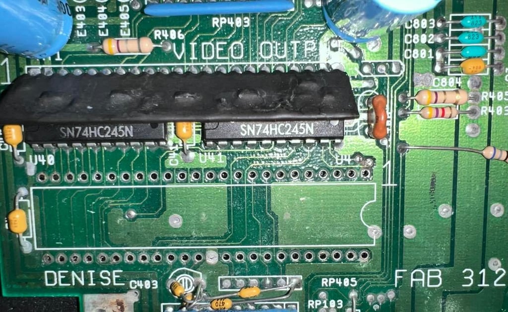
I do a test to see if the problem is still there (or even better disappear due to cleaning). But it is still there. No surprise. But I notice something now: when I push around the Denise area the fault seems to follow the pattern when I press down the Denise chip? See video below.
While continuing investigating I post a question at the Facebook group Amiga Tech Tips and Repairs. And I quite immediate get some suggestions:
Check for leaks of any kind
Test power supply
Clean the Agnus
Reseat the socketed chips (using appropriate tools), and clean their pins and sockets
The first two I think are ok. The power supply (PSU) is a modern version which I use with my A1200. I haven´t checked any voltages yet, but I will do that later. I think they are ok for now.
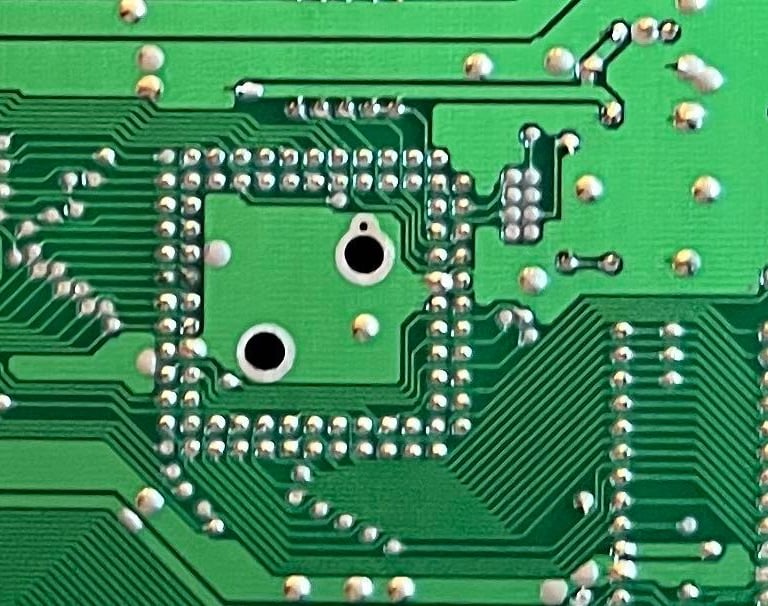
Next I clean the Agnus. I don´t have a PLCC tool unfortunately, but I manage to push the chip out from below trough the two small holes.
I do a quick test again after the Agnus is put back - same result. But this time it doesn´t seem to be so responsive when I press the Denise chip area. Strange...
Next I remove all the socketed chips, clean the contacts and the sockets. I do actually think that this could solve the problem. After everything is cleaned and all chips are re-inserted I test again... BLACK SCREEN! OH NO!
Oh my... I see the problem! I´ve inserted the Denise chip the wrong way! I re-insert it again, but still BLACK SCREEN! I´ve probably broken the Denise chip... hopefully I´ve not broken anything else...
Anyway, I decide to order a "new" Denise chip from Amiga Shop. I guess I need to wait for this before I can progress any furter....
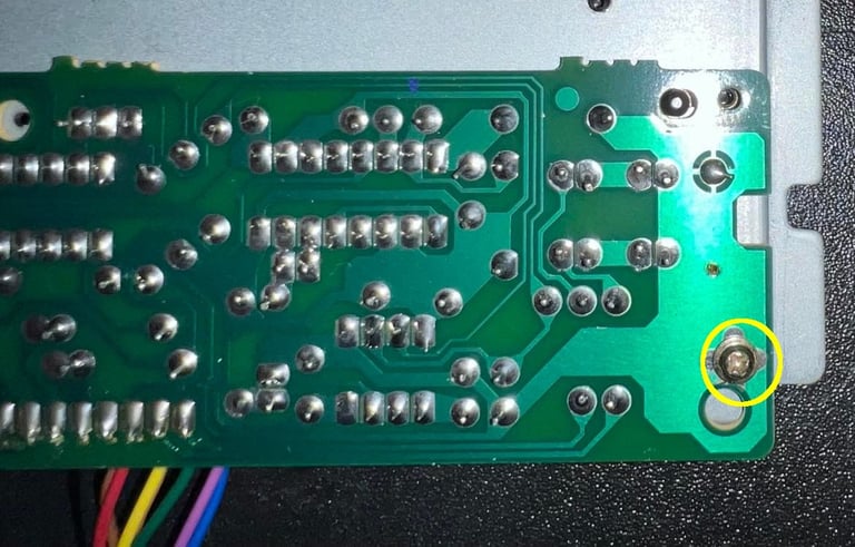
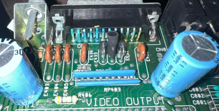
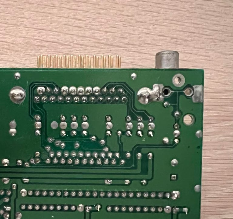
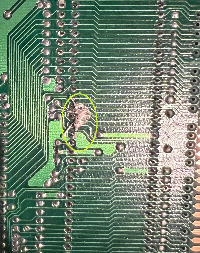
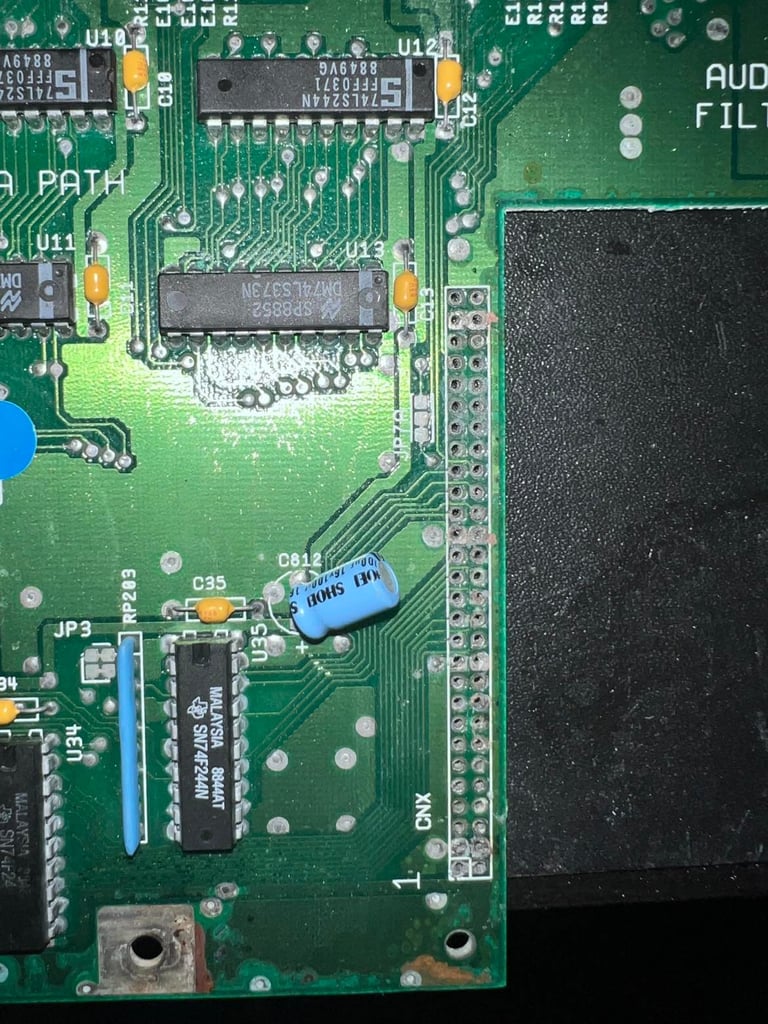
Ok! So I got a "new" Denise chip - time to try with the new one! But... still black screen! What?! Hm... this is not what I expected. Ehhhhhmmmm..... oh my.... what have I done?! This is embarrassing... Looks like I´ve spilt a huge blob of soldering iron under the CPU?! This is not something anyone else have done (the proof is in the pictures in the top of this article). I must be the culprit myself :-) See circled area in picture below.
After cleaning this mess I try again with both the "new" and "old" and it turns out that both works fine. That said, the flickering is still there - but I´m back to the original problem at least (but now I have a Denise chip in spare).
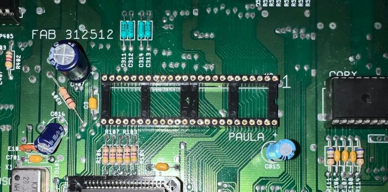
As shown in the video snippet above the fault seems to be worse/better when pushing/releasing the Denise chip area. This point in the direction that it could be a bad trace or corrosion in this area. Next step is then to desolder the socket holding the Denise, clean and check the connectivity . Picture below shows the area when the socket is desoldered - but before cleaning. Note that the one pad filled with soldering is not a broken one. It´s just one pad with a rather big connection area which is a bit hard to get the solder away. But I used a bit of hot air when removing the socket so no trace or pad were lifted. I do see that some of these pads are marginal - they don´t have very much metal left. This could mean that it´s beneficial with some bodge wires here.

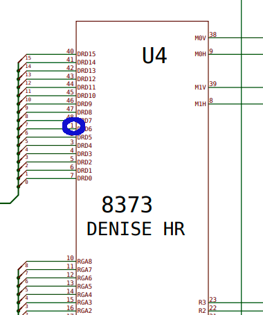
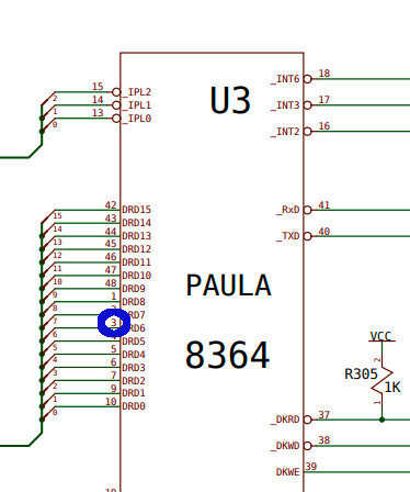
I start with checking the connectivity from the Denise pins to the surrounding components. And I identify a broken trace: pin #1 from Denise should be connected to pin#3 at Paula. But there is no connection here at all. Could this be the problem? Below is a picture from the schematics I use for this mainboard. You can download the schematics for the A500 Rev 6 version.
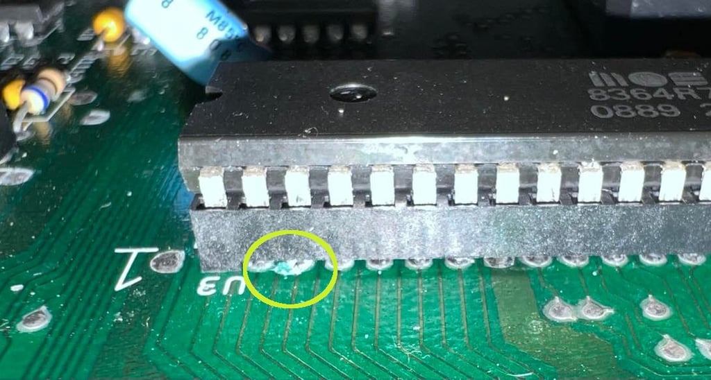
It seems like the problem lies with the via/pad at the Paula chip. Below is a picture of the Paula chip where pin # 3 is marked. It looks like there is some corrosion there.

First I remove the corrosion around the Denise chip. The way I do this is by applying vinegar and gently scrape the corrosion away. Maybe it´s not so easy to see on the pictures but the via´s for pin 25-30 looks quite "good" after this cleaning. I actually thought they were broken, but they look ok. It´s important to apply some solder on all the traces which have been cleaned for corrosion. Removing the corrosion often looks a bit ugly, but it´s only cosmetic. It´s much better to get the corrosion way properly. Also, after vinegar is used it´s necessary to clean with isopropanol. Below is the area after corrosion is removed, cleaned and solder applied on traces and vias.
A new modern dual wipe socket is used for the Denise. As I test I solder a temporary bodge wire between pin #1 on Denise to #3 on Paula. And guess what? Now it looks much better - picture is rock solid! No flickering or issues - and no response when pushing the Denise chip! Excellent! One fault found and fixed! See picture below!
As mentioned there are some corrosion around pin #3 on the Paula chip which cause a broken trace to Denise. Also I notice that there are some sign of corrosion also on the old socket itself. The picture below shows the corrosion in these pins (the picture doesn´t show this too good unfortunately, but it´s there). That means that this socket needs to be replaced also.
The socket is carefully desoldered by using a combination of the desoldering gun and hot air. No traces or pads are broken in the process, but after gently cleaning with vinegar, glass fibre pen and isopropanol it´s clear that the trace connecting pad @ pin #3 is broken. The best way to repair this is to use a bodge wire on the backside of the PCB. Note that there are other ways using e.g. small wires to re-create the broken traces but even if this may look better - it´s not robust. The best it to use bodge wires at the back. Picture below show the socket desoldered and all pads cleaned to prevent further corrosion.

After thorough cleaning a new socket is soldered in. Note that this socket is actually made up of 2 x 24 pin sockets.
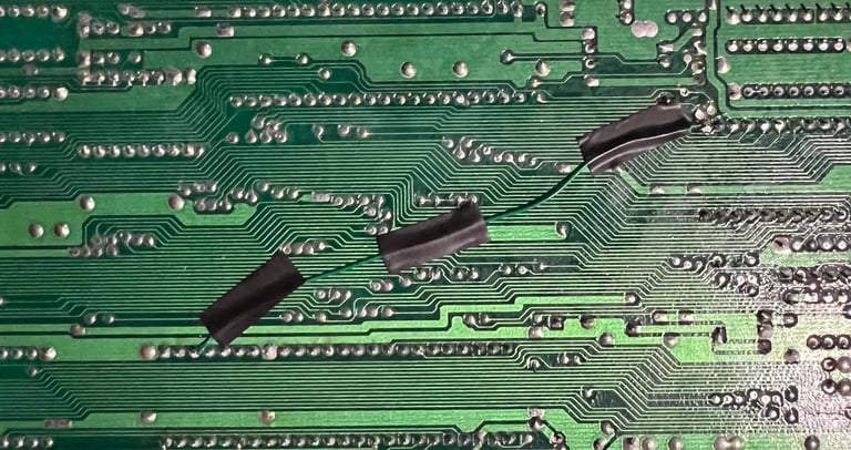
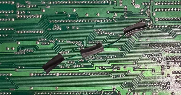
With the new socket in place for Paula, the bodge wire between pin #1 @ Denise and pin #3 @ Paula is soldered in. Three small pieces of insulation tape function as strain relief.
As previously mentioned the area around the trap door expansion, and the connector itself, is quite corroded - and have this strange "stuff" around it probably due to a leaking battery on the memory expansion. The machine now seems to work, but I would like to increase memory to 1MB. My first plan is to remove the existing connector and replace it with a new one. But which one to use? I´m not really sure how to deal with this situation so what to do? Ask for help!
One great way of getting help is using Facebook communities. I post a message asking for help at Amiga Tech Tips and Repairs (check Online resouces). And it surprises me everytime how fast and helpful people are! There are so many talented and nice people out there! Thanks all! Here are some of the advices I received (no special order):
Replace the connector with a new one. These should be standard 2.54mm dual row 90-degree headers with at least 8mm pins on the mating side to make sure the memory expansion works reliably.
Wait with desoldering - try to clean with acetic acid (white vinegar), clean with isopropanol and check connectivity with multimeter
I think I will try to replace it with a new one. Since these are standard pin headers they are not too expensive. I guess the toughest part is to desolder this due to all the corrosion...
... but the desoldering is not that hard. Since the connector will be replaced I choose to cut the legs and desolder each pin one-by-one. This is time consuming, but probably the most gentle way.
Below is a picture of the area with the connector desoldered. There are some corrosion in this area, but I think it´s possible to stop this corrosion and repair broken traces with some bodge wires.
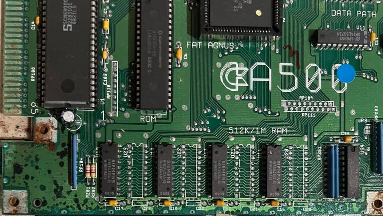
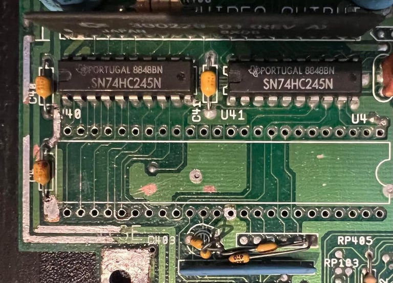
Again, I ask Amiga Tech Tips and Repair for some advice. I plan to remove the corrosion, but there is an area on the mainboard where there is space for four additional RAM chips. Can I use these instead of the trapdoor memory expansion? The trapdoor is used only for the additional 512 kB of RAM, but if I can place this RAM direct on the mainboard that would probably be better. I need to remove the corrosion nevertheless to stop further corrosion. Below is a picture of the memory area where the four additional RAM chips may(?) be placed.

I get a lot of feedback from Amiga Tech Tips and Repair. Here´s the key points:
Remove the corrosion with citric acid (5%) and a glass fibre pen. This percentage can be achieved by diluting white vinegar (35 %).
It is important to clean away the citric acid afterwards. Use water and isopropanol. Watch out for white "residue" the next day which is an indicator that there is still corrosive agents not washed away.
It is possible to replace the Fat Agnus with a 2 MB : https://icomp.de/shop-icomp/en/shop/product/ace2.html?fbclid=IwAR1wrLHMAptYVt6zAWfTn-DdN0lYIiRD10jcR0ZRhdvZY3T7YZ94wGX6Esg
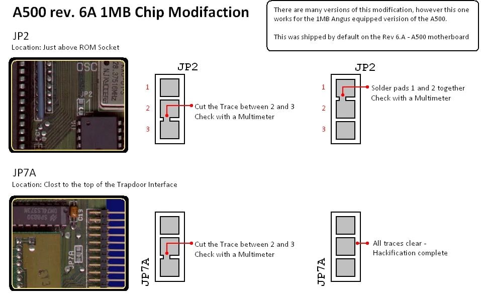
Yes, it is possible to add additional RAM on this revision 6A mainboard to get 1 MB of RAM. Link to HOW-TO: https://wiki.preterhuman.net/HOW_TO_INSTALL_1MB_CHIP_INTO_AN_AMIGA_500?fbclid=IwAR2u4YA78yXk0uN68m2sqgA1eodoGeyTJQj8lalDz4U63AQ6wYmn9XHCuhI
I got a good instruction page from Johans RetroData (Facebook page) on how to get the 1MB RAM on this mainboard:

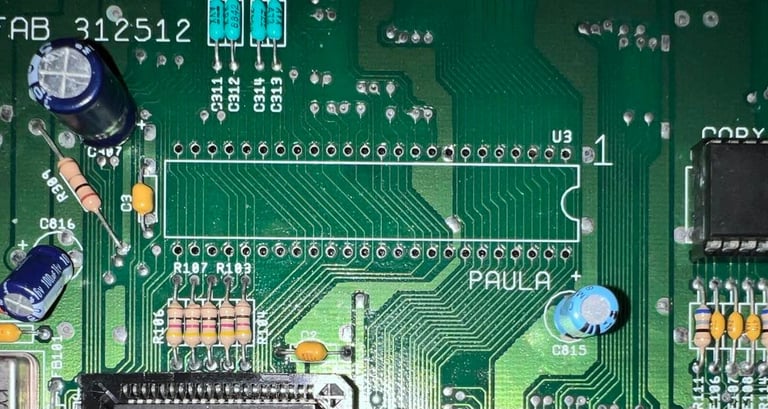
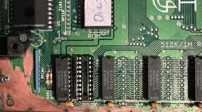
First thing I do is to remove U20 RAM module and the the soldering for RAM to be placed in U23. Also I try to remove most of the corrosion from the pads. It doesn´t look too bad, but there are quite some corrosion.
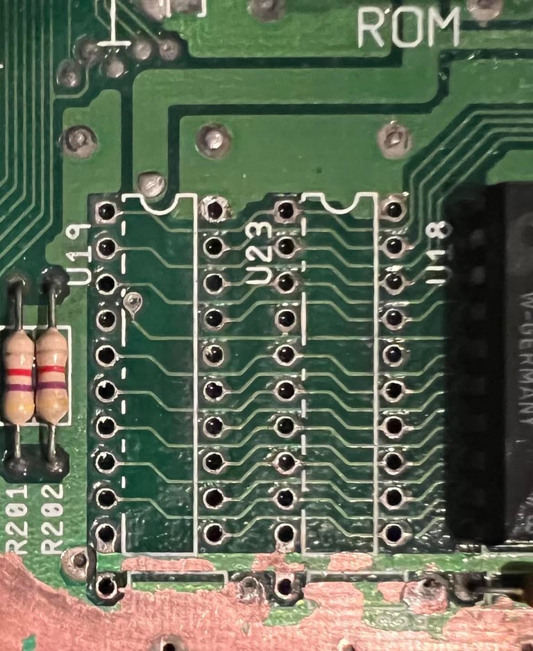

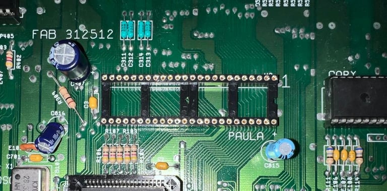
Then I solder in two new sockets for these two positions. It´s not easy to solder these back in since most of the traces goes on the top of the PCB. That means that there isn´t much to solder on the back. Also, notice that a lot of the corrosion around this area is removed now. It may not look too so nice, but it´s way better to try to stop this corrosive action.

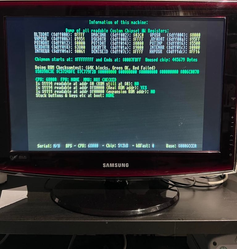
To check that the Amiga still works after this clean-up I power the machine back on. But... argh... red/green flashing colors. See short video here. According to the Amiga DiagROM color codes the flashing red/green indicates "Detected Chipmem errors". Well, I don´t think that the chipmem is in fact faulty, but I guess I´ve provoked a broken trace by the cleaning. This is probably something that would happen anyway due to slowly corrosion, but with my cleanup I´ve may have accelerated the process.
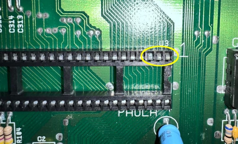
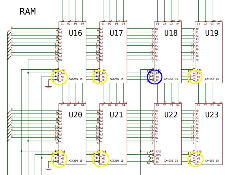
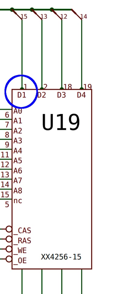
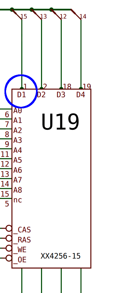
With the multimeter and the schematics for the A500 REV 6A mainboard I identify that there is a broken connection between Pin #3 on U23 and Pin #3 U18. See schematics below. When measuring between these pins (circled with yellow / blue to identify that somewhere between is a breach) I get no connection.
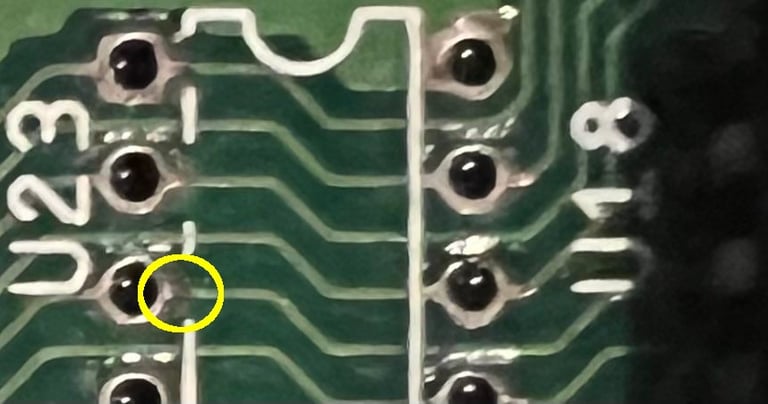
With closer inspection on the picture of the traces / pads before soldering in the new sockets I see that there might be a broken trace there on pin #3. But it´s not easy to be 100 % sure. In the picture below I´ve zoomed in and circled the pin. I see that there are some dark area on the right side of the pad for pin #3. Could this be the culprit? That said, I think that several of these looks a bit suspicious.

It turns out that this doesn´t solve the problem. Still the red/green flashing colors. I continue to check for broken traces and I find another one. Between pin #1 and pin #9 on RP109. See schematics below.
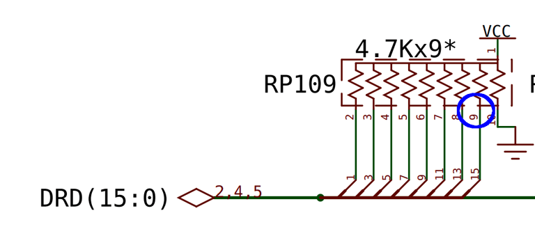
Another bodge wire is soldered in to replace this broken trace. And with this wire in place a familiar picture appears.

Update: This machine will be used for parts / testing.
In order to "rescue" another A500, Rev 6A, the Fat Agnus of this mainboard is used. So at the moment this machine no longer has a Fat Agnus chip...
Banner picture credits: Ajne01