
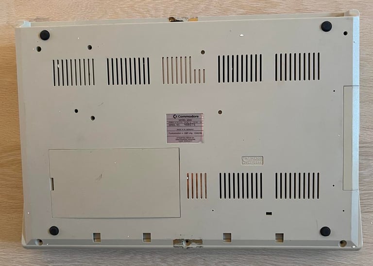
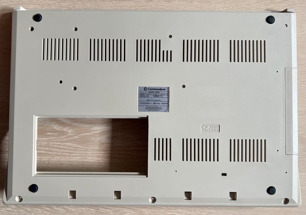
Amiga 500
Ser. No. 488075
Assy 312510
Artwork 312513 REV 6A
Starting point
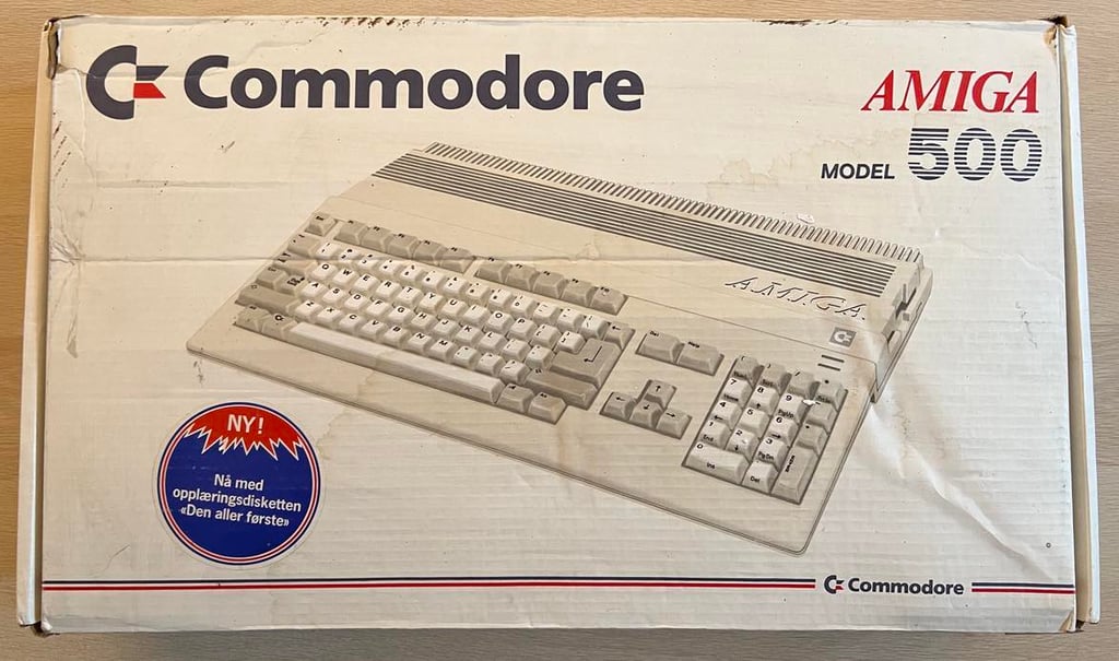
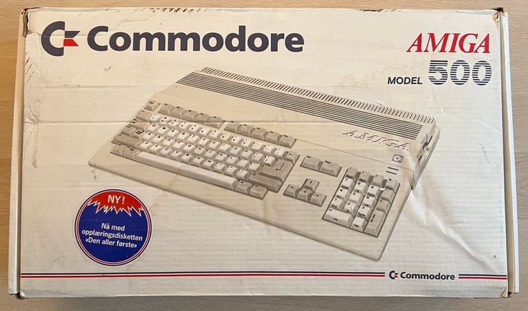
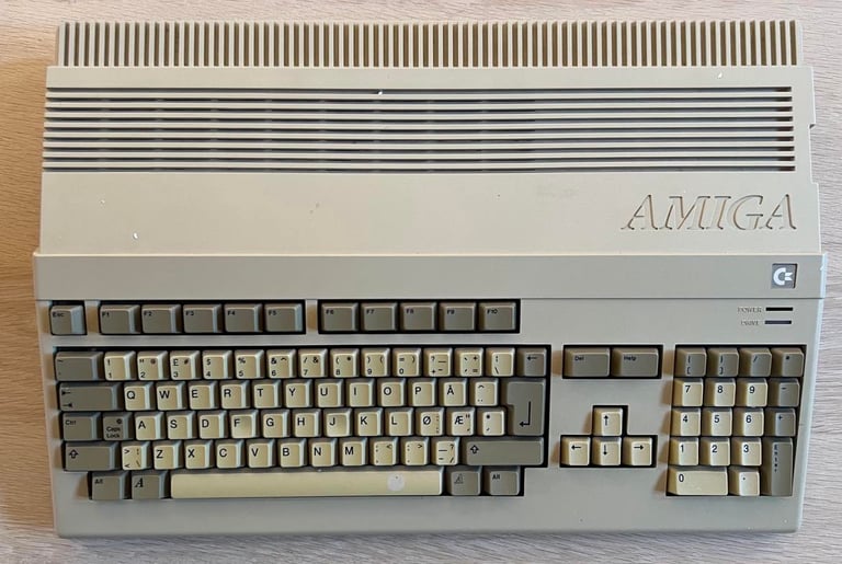
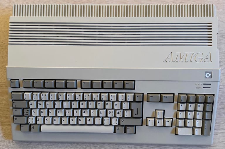
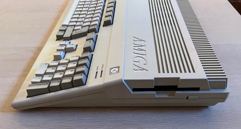
This Amiga 500 has been sent to me for repair. At the time of writing I do not know the symptoms other than it is faulty so I will investigate the symptoms later. The machine was shipped in its original box which I think is very cool. This is a Norwegian Amiga 500 which means that the keyboard contains the letters "Æ, Ø, Å". Also, notice that there is a label on the front saying (in Norwegian): "New! Now with the training disk `The very first´."
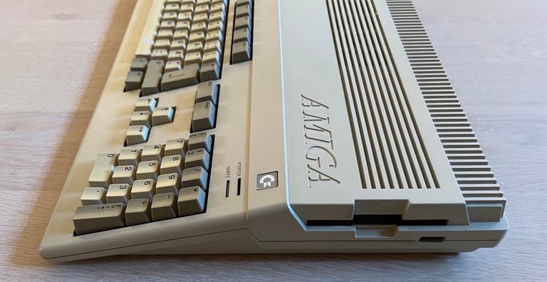
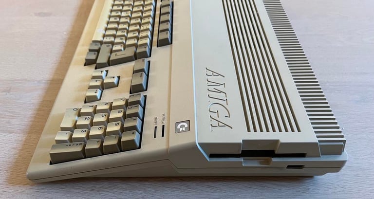
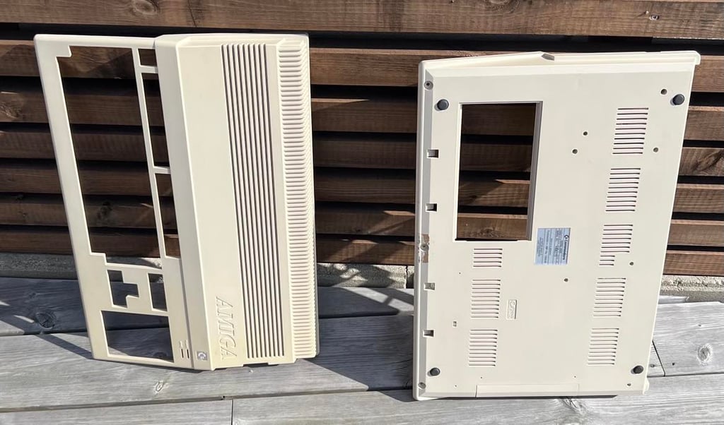
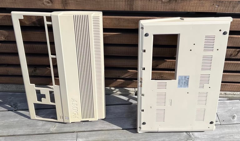
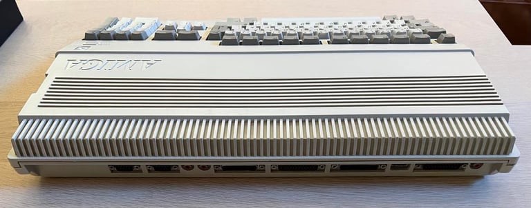
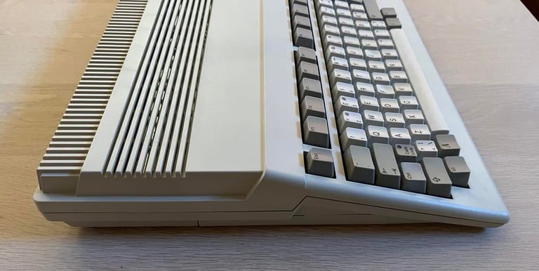
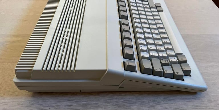
From the outside the machine looks to be in OK condition. There are some dirt and dust - and the keyboard is quite yellowed - but I can not see any major damage from the outside of the machine. As can be seen from the right hand side picture of the machine the floppy drive is missing. But that is fine since the plan is to repair the mainboard. And I have floppy drives for testing purposes.
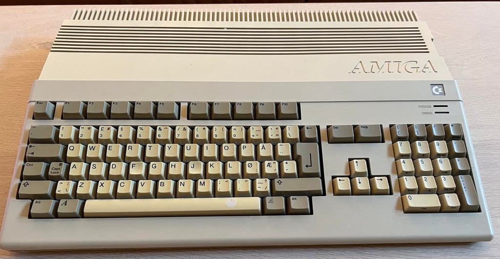

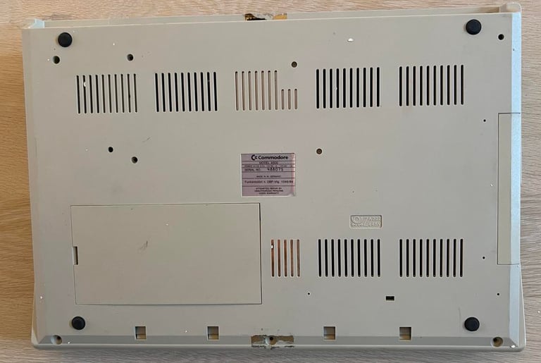
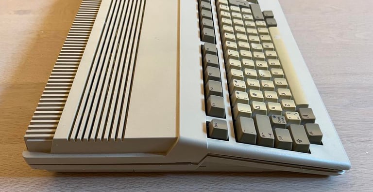
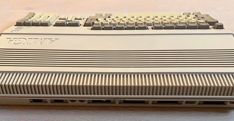
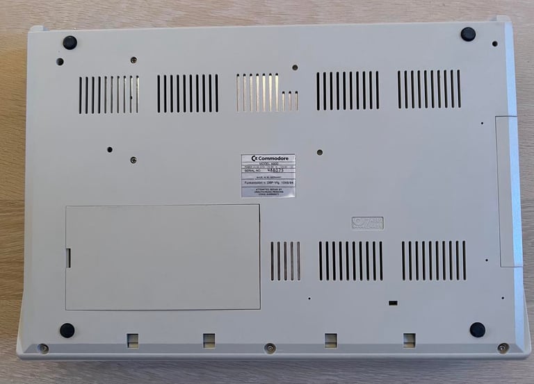
All the screws on the bottom are missing and the casing is partially open, but other than that it looks to be intact.
Refurbishment plan
This will be probably not be a complete refurbish of a Amiga 500, but primarily a repair. The plan is to:
Repair mainboard
Verify operation by testing
The plan will be updated during the the repair / refurbish.
Updated actions:
Repair keyboard
Install internal floppy drive
Repair A501 RAM expansion
Replace electrolytic capacitors on mainboard
Replace electrolytic capacitors on A501 RAM expansion
Opening it up...
Main unit
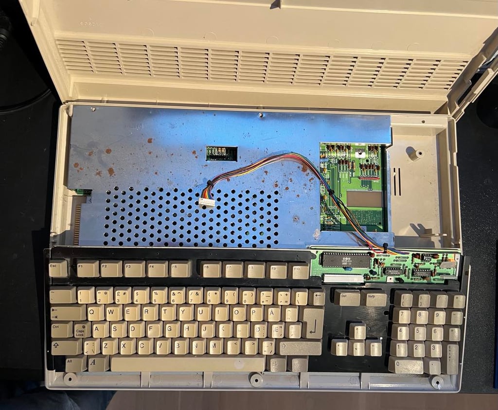
Opening the machine is very easy. There are no screws:-) And the top cover is partially lifted already so it is just to remove it completely. This reveals the inside. As can be seen from the picture below the keyboard connector is removed. And I also notice that the POWER LED is bent out of position.

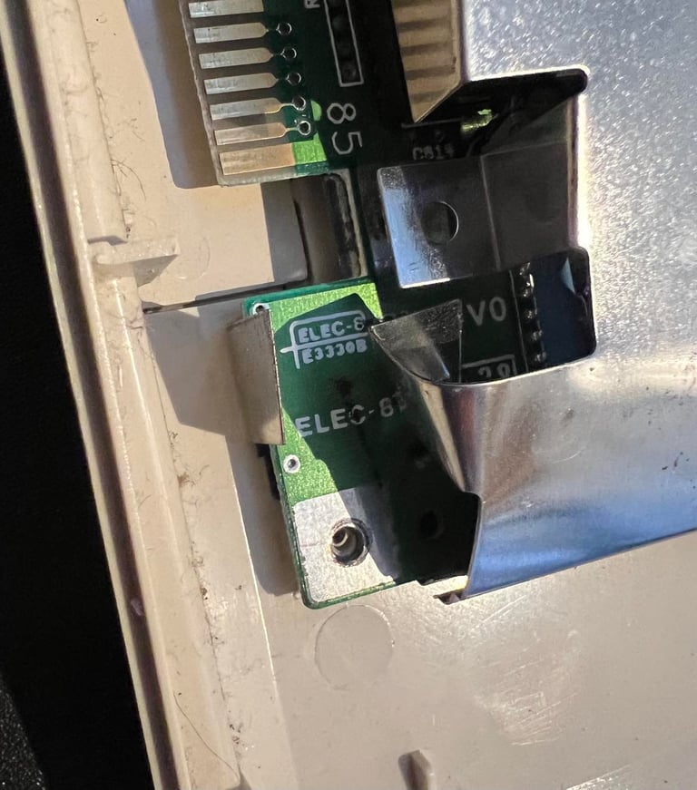
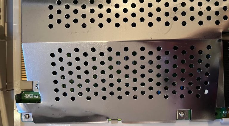
When the keyboard is removed the RF-shield is fully revealed. There are some corrosion on the shield, but not too bad. I have seen much worse. But I notice that the RF-shield is lifted/bent on bottom left side. See pictures below. It is not something that should be a problem, but it is something I will try to fix.
Also, I see that there is a A501 512 kB memory expansion connected to the expansion slot. Notice that there are no screws on the RF-shield either...
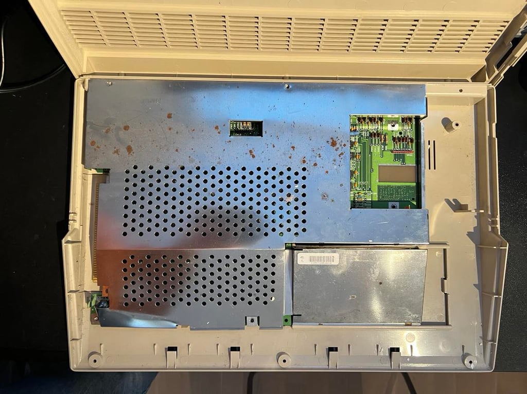
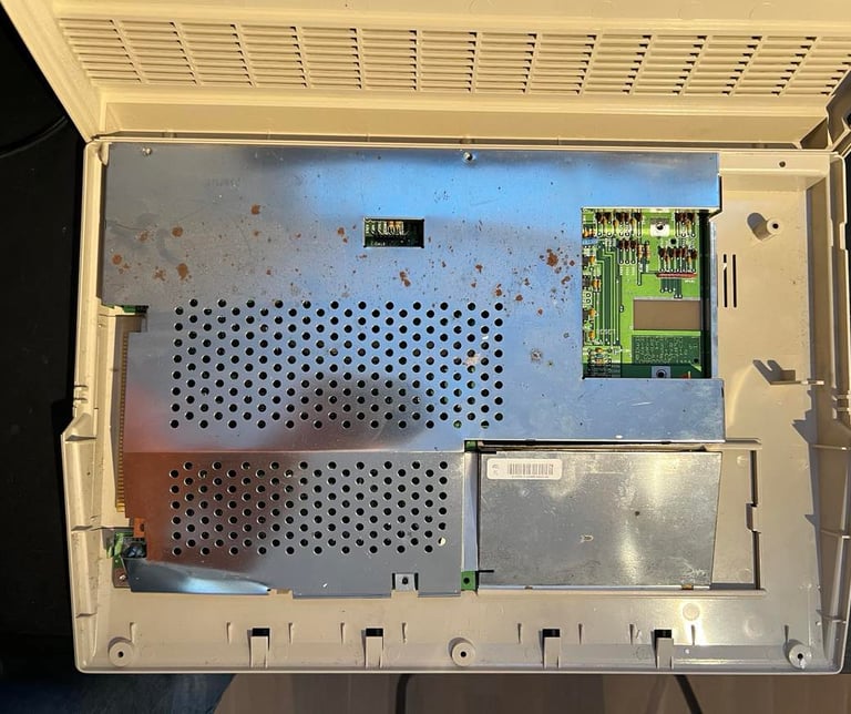
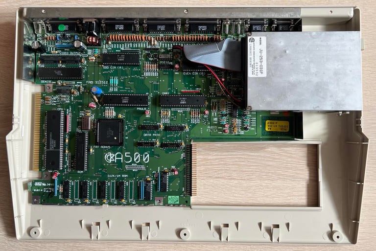
And since there are no screws holding the RF-shield either it is just a matter of lifting the shield off the PCB. This will reveal the mainboard PCB. See picture below. The A501 RAM expansion is removed.

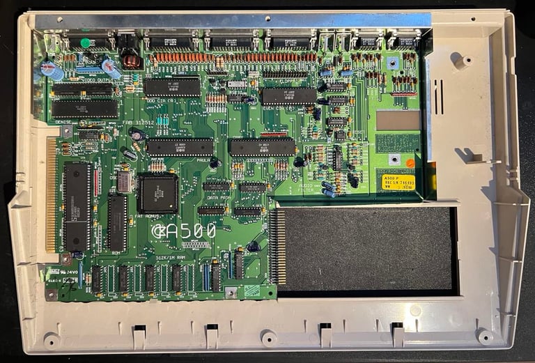
Screws holding the PCB to the bottom cover? Nope. But on the bright side the PCB looks to be in good condition. There are some minor corrosion on the bottom edge of the PCB, but this is marginal. So even if the machine is reported as "faulty" I am positive that there is hope that this machine can be repaired.
A501 RAM expansion
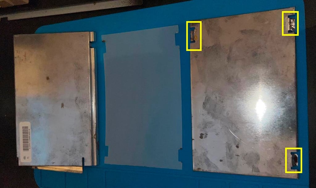
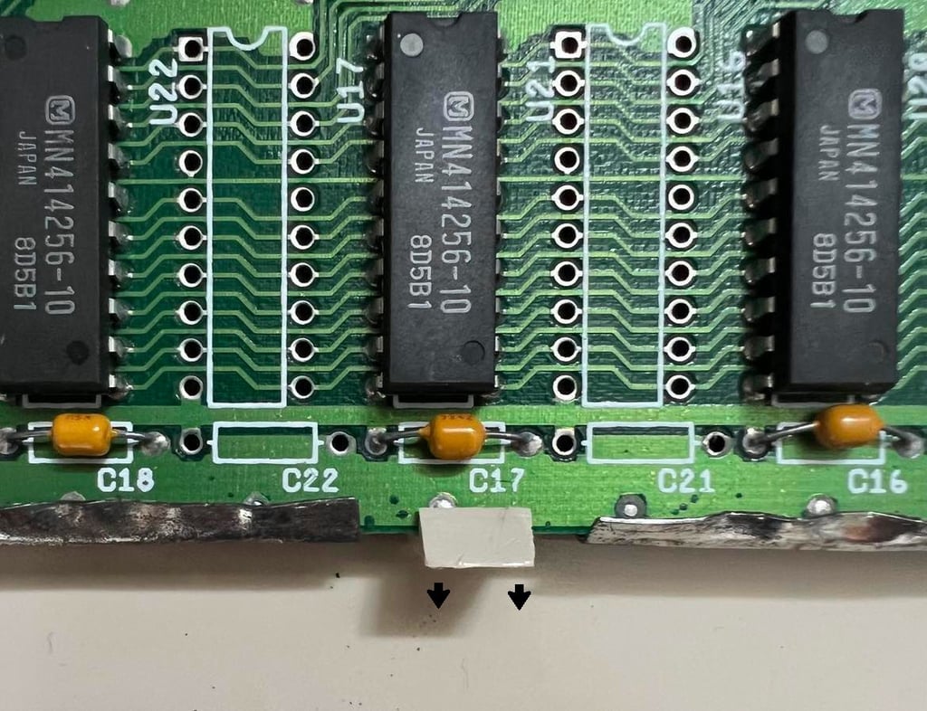
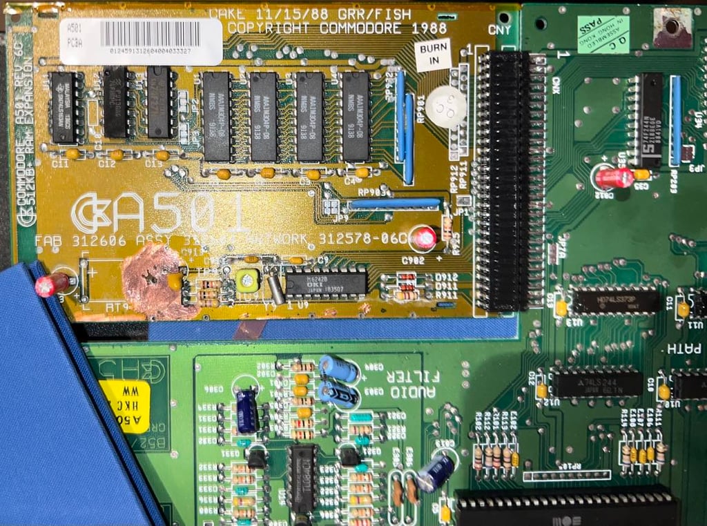
To open the A501 RAM expansion the metal shielding needs to be soldered off. There are three solder points (see yellow squares) that connects the top- and bottom shield of the unit. While holding the soldering iron on each point the two parts are pried apart. As can be seen from the picture below the shielding consists of three parts: top shielding, an insulating cover and the bottom shielding.
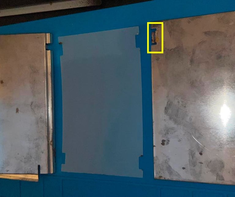
It is no surprise to see that there is significant battery leakage inside which will completely destroy the PCB / components if is not removed and repaired. But, luckily, it seems like the leakage and corrosion is limited so I have high hopes that this RAM expansion can be repaired. Picture below shows the PCB and the yellow squares indicates the most damaged areas which needs to be checked and repeared.
Exterior casing
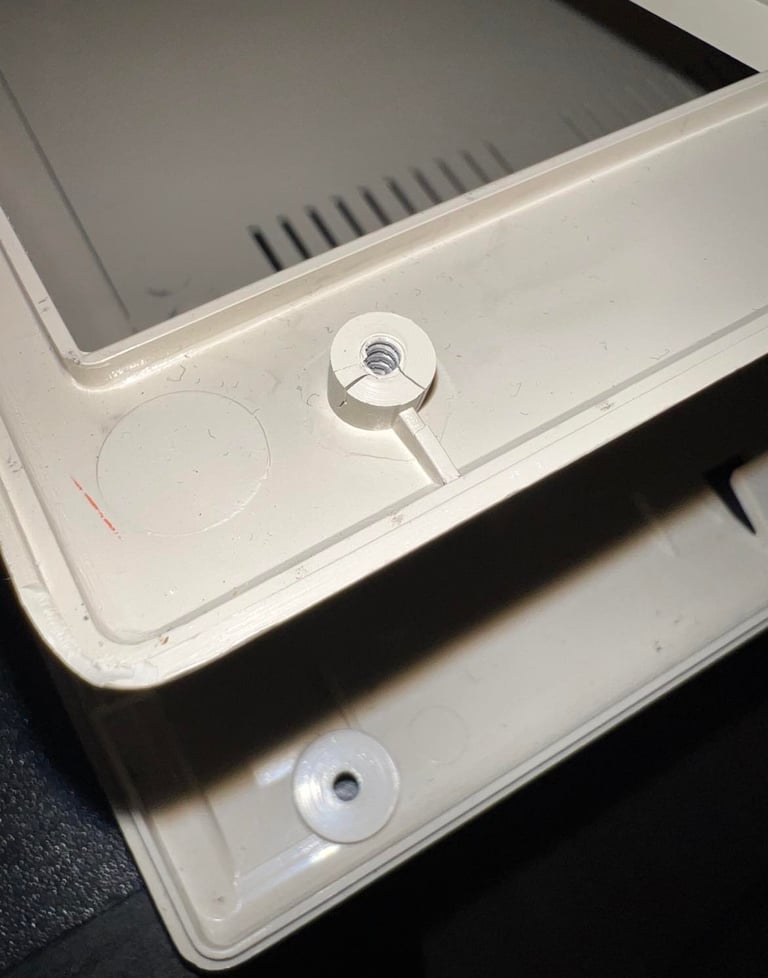
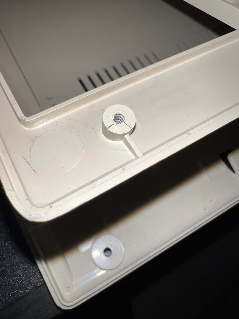
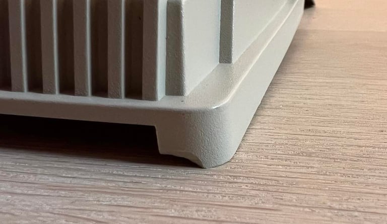
The top- and bottom cover are cleaned with mild soap water. It is not very yellowed, but I choose to place both covers in the sun for a few days (while there are some sun here in Stavanger, Norway). Unfortunately, several of the plastic parts for the screws are broken. I am not sure how much this matter (since all the screws are missing), but I will find out later.
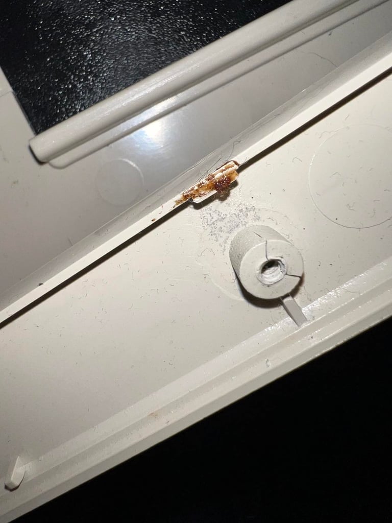
There are some sticker residue which does not look to good. This is removed with isopropanol. When the stickers are removed I notice that there are some scrape marks beneath this. Someone has opened this machine with quite "heavy" tools...
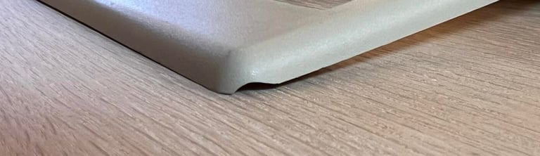
On the top cover there are two places where a piece of the plastic is broken. But it is marginal so I think it should be ok. Again, I can not be sure, but it appears to me that this machine has been opened with brute force...

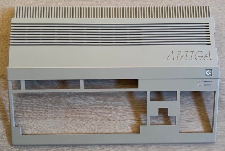
Below are pictures of the top- and bottom cover after cleaning. The cleaning is done with a combination of isopropanol, baking soda, glass cleaning spray and soap water.


Unfortunately the small plastic "lock" snaps off. This plastic part is extremely brittle after 30+ years - and these things happens from time to time during refurbish. Nevertheless, this is easily fixed by adding some small transparent tape which will hold the lid in place.

After some careful twisting and bending the shield is repaired. Also four brand new screws are added which now holds both the shield and the mainboard attached to the bottom cover.

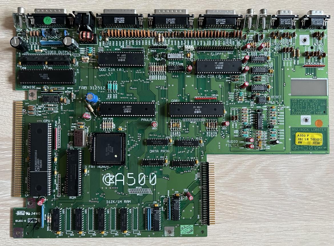
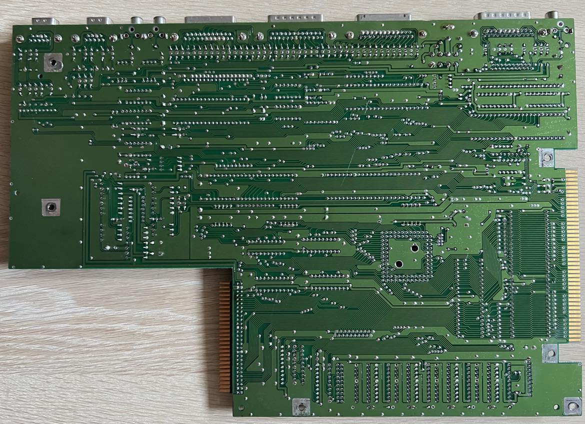
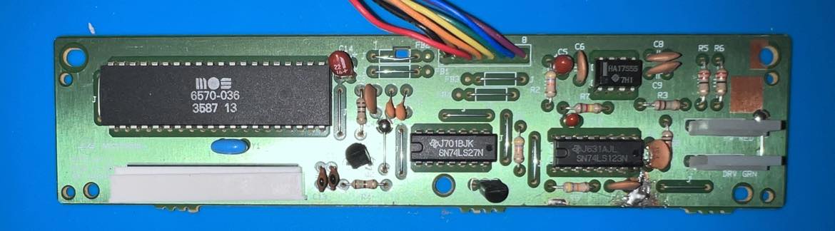
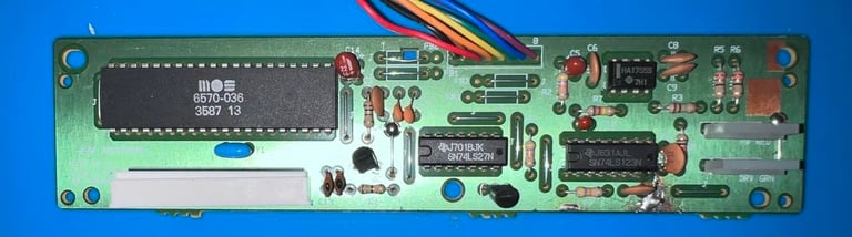
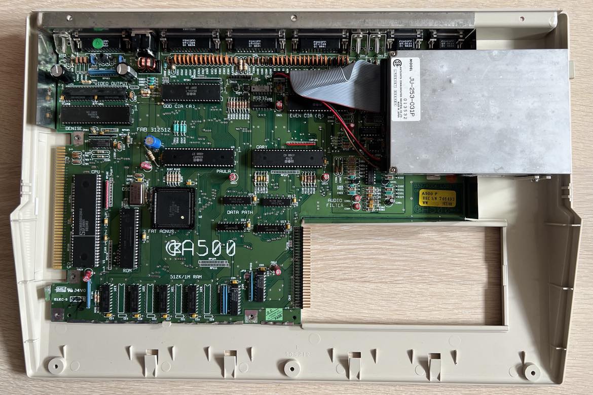
Mainboard - repair
This is a REV 6A mainboard - assy 312510 artwork 312513 - which is the last revision of the A500 mainboard before the A500+. The REV6A mainboard is also known as a "ECS" mainboard which is short for "Enhanced Chip Set" offering up to 1 MB of chip RAM (compared to "Original Chip Set (OCS) which only allow for 512 kB of chip RAM).
Initial testing - investigating the faulty symptoms
The mainboard is connected to a screen and a known working power supply (PSU) and then turned on. The TV shows only a black screen, but there is obviously a video signal. So the Denise chip is at least providing a video signal to the TV - although it is completely black.
Visual inspection of the mainboard
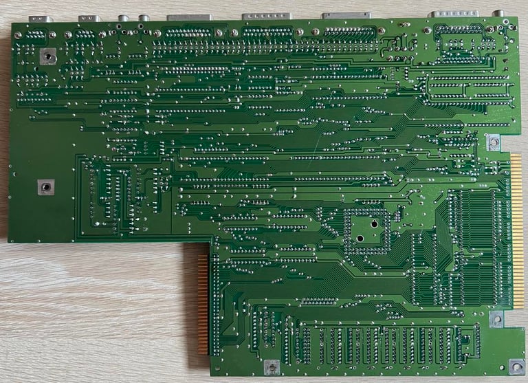
The mainboard is in an overall good condition. I can not see any damage or severe corrosion. There are some minor rust on the ground plane on the edge of the PCB, but this is marginal and will not result in any problem.
In the table below all the major custom IC found on the mainboard is listed.
As can be seen from the table above most of the custom chips were produced during 1988. The only exception is the Denise chip which was produced in week 33 in 1991. My guess is that this chip has been replaced at some time. The Denise chip is responsible for handling graphics and video output.
Cleaning the socketed IC
It is not unusual that an Amiga 500 can stop working due to poor connectivity between the pins on the ICs and the mainboard. So all custom chips which are socketed (see table above) are removed and cleaned individually with glass fibre pen and isopropanol. NOTE: when removing the Fat Agnus chip a PLCC extractor must be used in order to avoid breaking the socket (or damaging the chip).
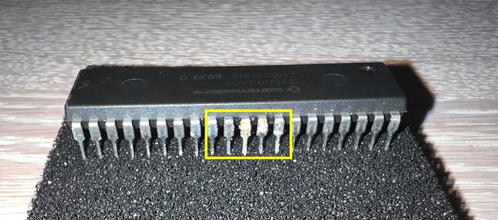
When removing the Kickstart ROM I notice that some of the legs are partly corroded (or oxidized). Could this be the fault? See picture below.
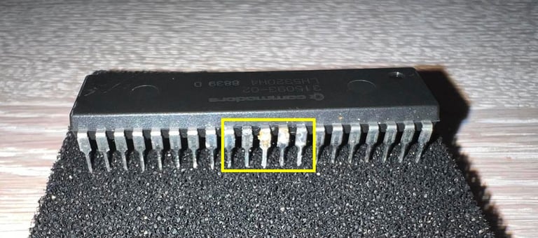
But it turns out that this is not the problem. Or, it would potentially be part of the problem, but even after cleaning the chip very carefully with glass fibre pen and isopropanol the A500 still does not work. Black screen.
Checking the voltages and signals
The +5 V DC and ground connection is checked on several of the chips. And I can not find anything wrong here. The voltages are all quite close to 5.0 Volts and all ground connections I check are ok.
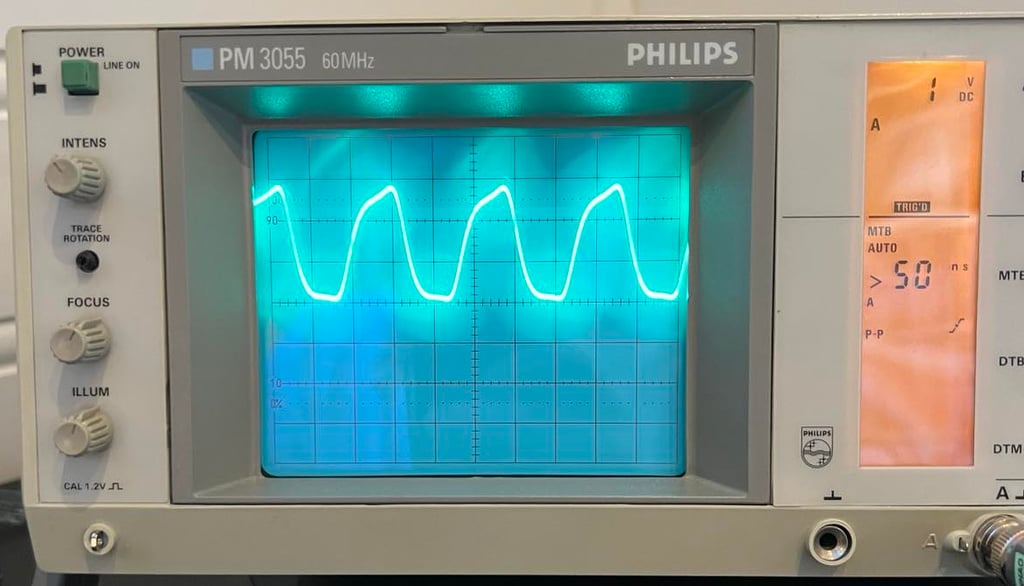
Using the oscilloscope I check the clock input first on the 68000 CPU on pin #15. I find this clock signal a bit odd; the shape of the signal does not look very square and the peak-to-peak voltage is only about 2.8 V. This could also be due to my oscilloscope being old and only having a 60 MHz bandwidth, but it still looks a bit strange to me. But the frequency is correct. As can be seen below the oscilloscope is set to 50 nS / DIV and doing some rough calculations ( 1 / (2.8 * 50 ns) ) = 7.14 MHz which is about right. See picture below.

Continuing with the oscilloscope I check the data- and address lines on the 68000 CPU. And now something odd happens. While probing the address lines A1-A16 they are all completely "stuck" around 0 V. Something seem to pull these low - or stop the CPU from executing. I check the /RESET and /HALT pin, but they are both +5 V so nothing seems to deliberately stop the CPU from running. But now something weird happens. When I power cycle the machine a few times I suddenly get "perfect" signals on all the address lines (!). And the screen turns grey with some flickering. I power cycle a few times more and about 1 out of 5 times a greyish color appear.
Could it be just a bad connection somewhere? With the machine powered on I try to push/knock the ICs to see if I get any respons. But nothing... the only thing I notice is that the 8372A Fat Agnus is very hot. I know that this chip can be quite hot, but it doesn´t feel quite right. Using the PLCC extractor I remove the Fat Agnus and carefully clean all the pins and connector (again). But this doesn´t fix the problem either.
Now I notice something else also. After cleaning the Fat Agnus is cold when re-installed. And the chip is cold when the machine is "Black screen" mode. But when the greyish flickering occur from time to time the chip gets very hot! Could the Fat Agnus be broken? Or marginal?
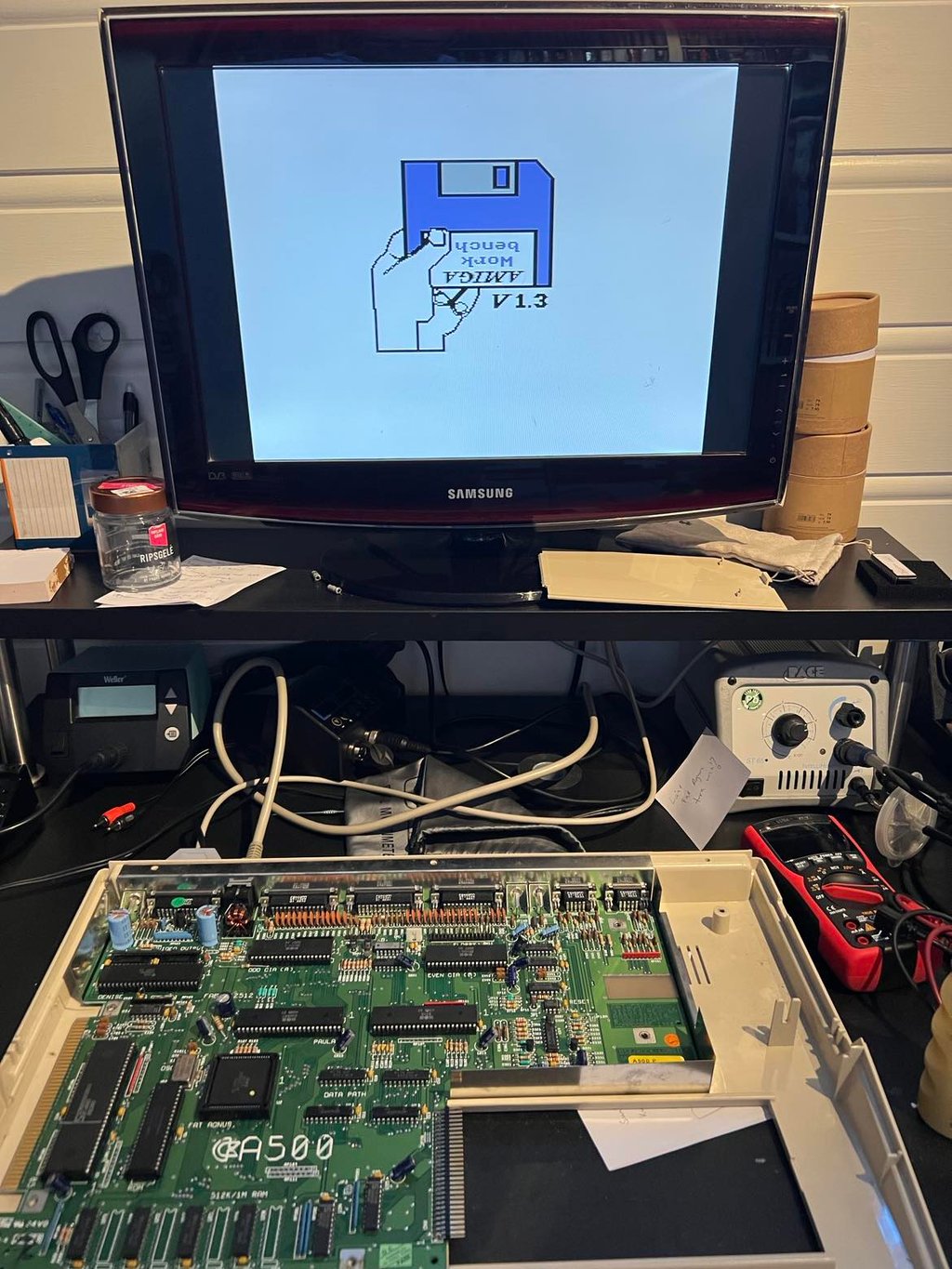
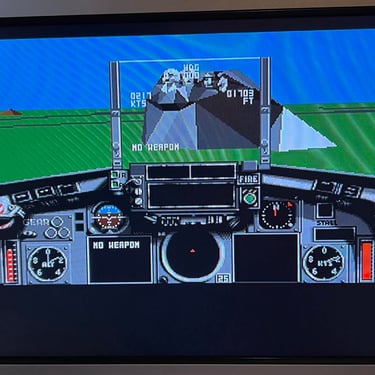
I replace the Fat Agnus with a known working 8372A from a different machine (A500 same mainboard version). And... success! The default bootup screen occur! See picture below.

Continuing testing
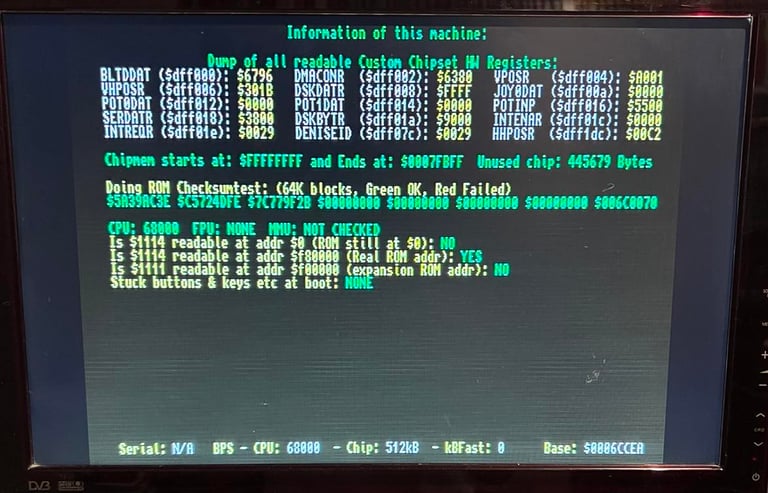
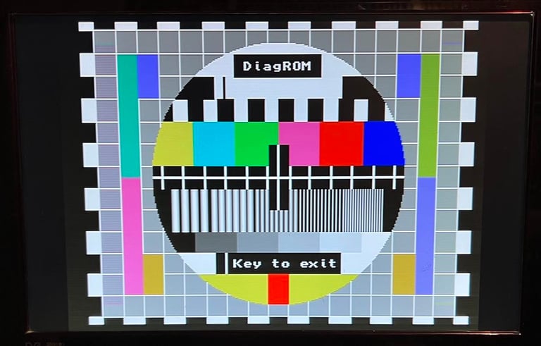
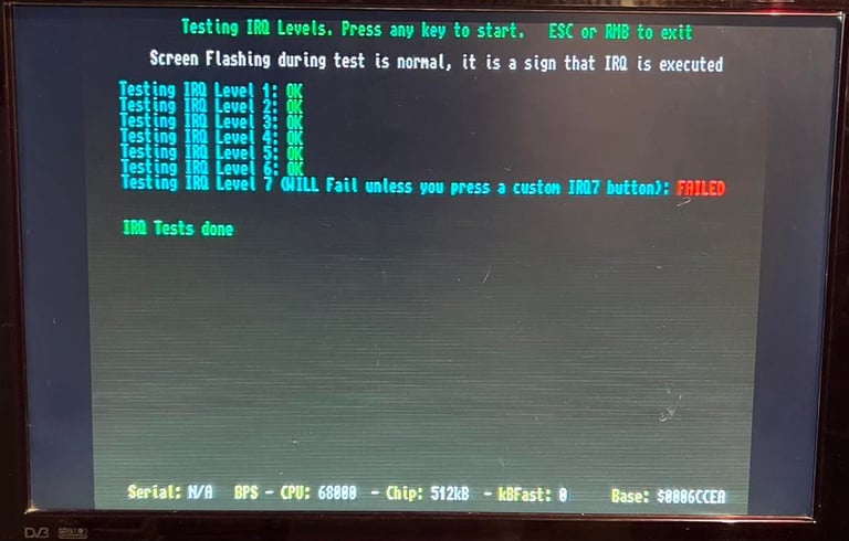
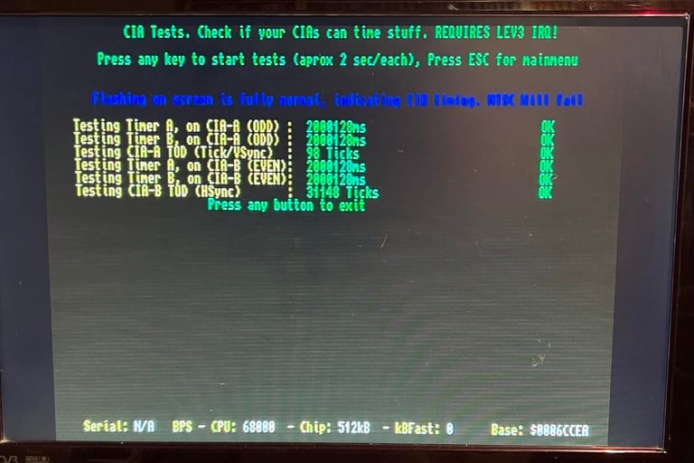
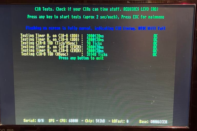
Even if the machine is now starting up it doesn´t necessarily mean that it is working as it should. So the next step is to remove the Kickstart 1.3 ROM and install the Amiga DiagROM chip. With this chip I can run quite a few initial hardware test on the machine without having the disk drive connected. The keyboard needs to be installed though.
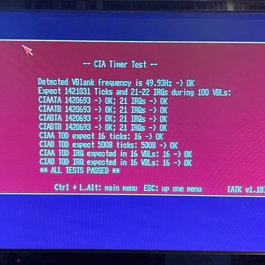
With this DiagROM chip installed I run some test - and as far as I can see they all pass. I can not find anything wrong so far. Below are some screenshots from the testing.


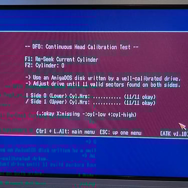
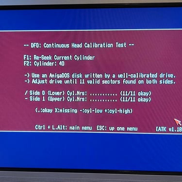
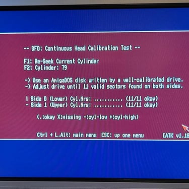
Testing with the Amiga Test Disk
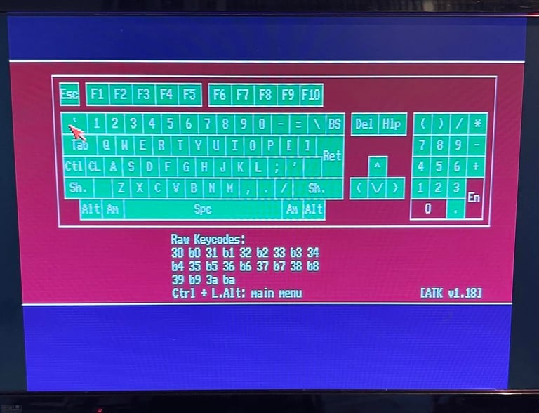
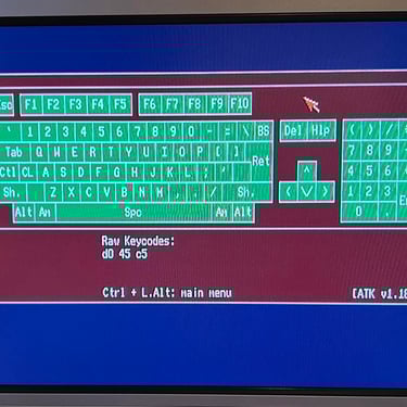
Next step testing the basic functionality is done using the Amiga Test Disk (by connection an internal disk drive). This disk has several good tools for testing the machine´s functionality. All major tests pass without any issues - with the exception of the keyboard test where the "Enter" and the "0" on the right hand side keypad is not working. Below are some pictures from the testing.

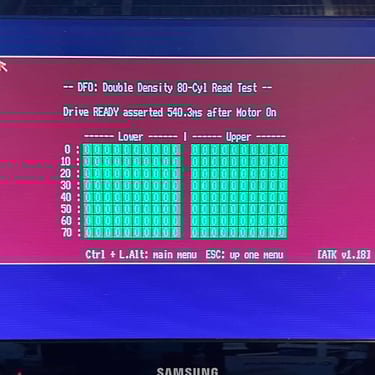
The only test which is not 100 % is the keyboard test. As can be seen from the picture below the "0" and "Enter" key on the keypad are not registered when being pressed. This needs to be investigated for repair.

Mainboard - Cleaning and recap
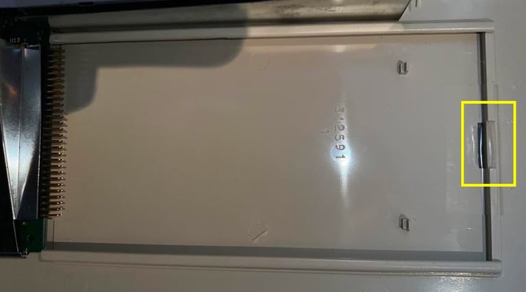
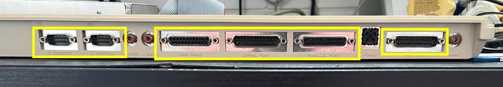
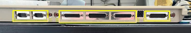
Before the mainboard is cleaned and all the electrolytic capacitors are replaced, the bottom metal shielding is removed. This is done by:
Bending the metal "tabs" surrounding the PCB upwards so that the PCB is freed
Removing the 12 screws on the back holding the different ports
Gently pushing the plastic clip downwards

The mainboard is cleaned with isopropanol and a Q-tip. All the old 17 electrolytic capacitors are replaced with new quality capacitors. Is is not really straightforward to desolder these capacitors due to the quite large ground plane on the Amiga 500. This large ground plane makes it hard to get enough heat to desolder, but using a combination of both a soldering iron and desoldering gun I manage to recap the board without any damage.
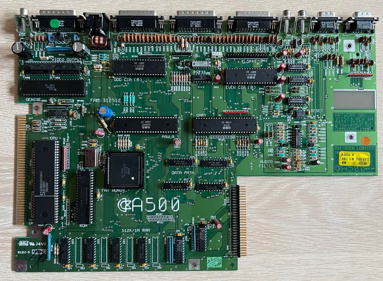
Below are some pictures of the mainboard after cleaning and with new electrolytic capacitors.
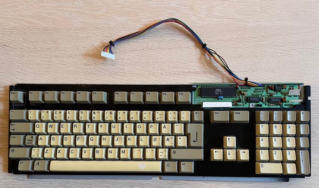
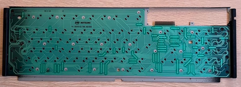
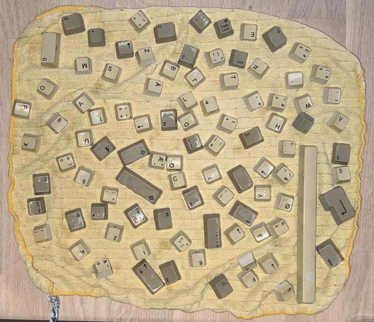
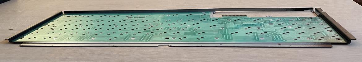
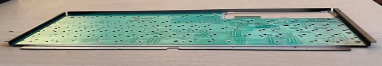
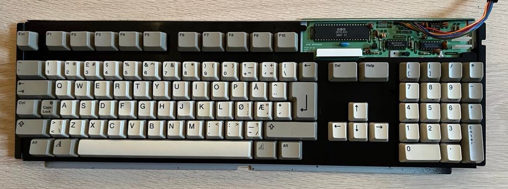
Keyboard - repair
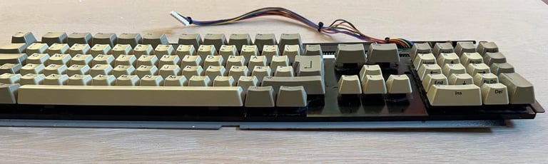
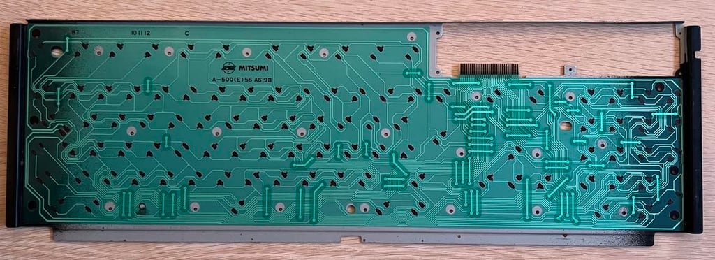
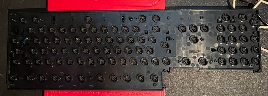
As seen from the pictures below the Mitsumi keyboard is a bit yellowed, but looks to be intact. When doing the initial testing I noticed that some of the keys were not registered as being pressed unless i pressed hard / tapped the key several times. So there are obviously something that needs to be fixed with this keyboard. Also, I notice that the whole backplate is bent upwards on the right hand side. Could this be part of the problem why keys are not detected as being pressed?


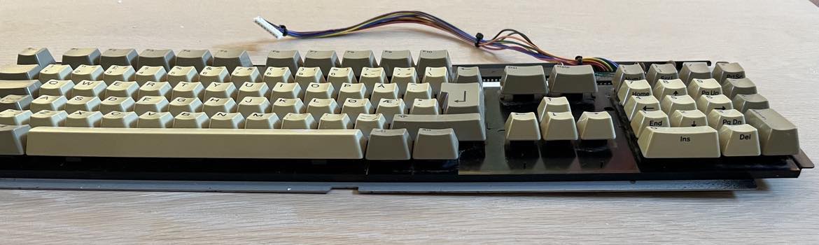
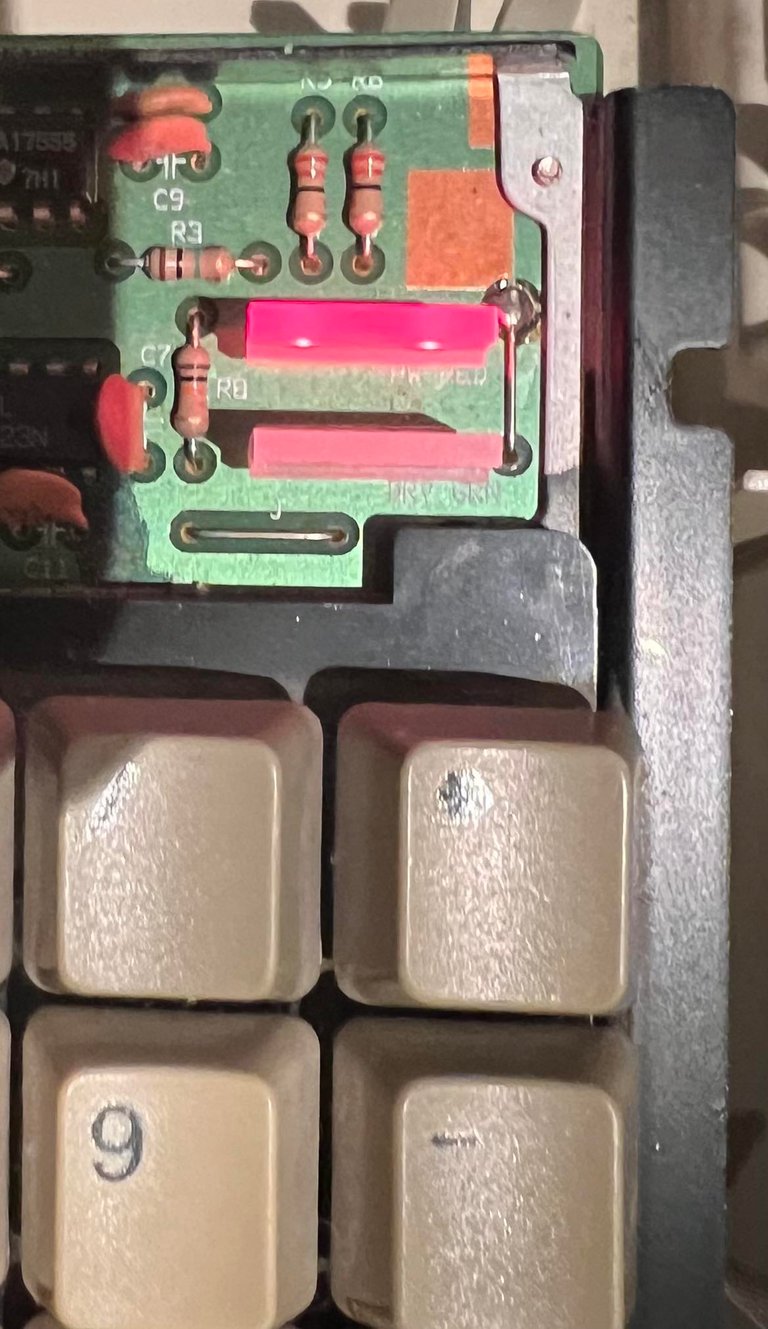
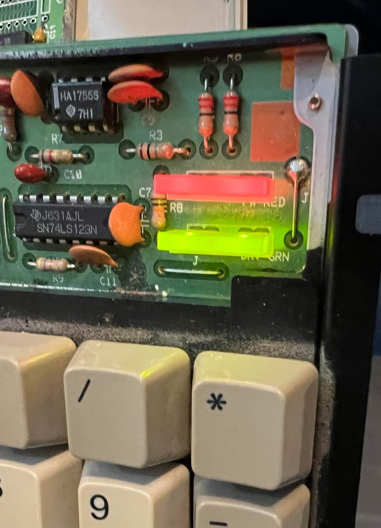
As previously noted the POWER LED is bent. With some care I manage to align this with the DRIVE LED. Also, the POWER LED works as it should when the keyboard is connected. Also, the DRIVE LED works as it should when floppy drive access is executed.


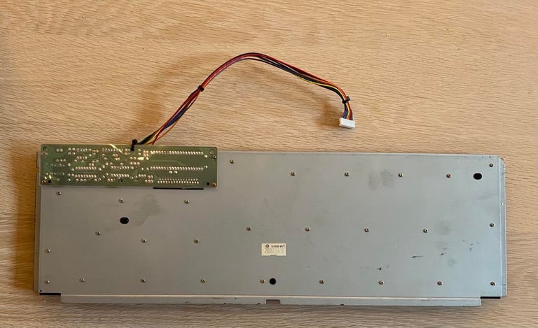
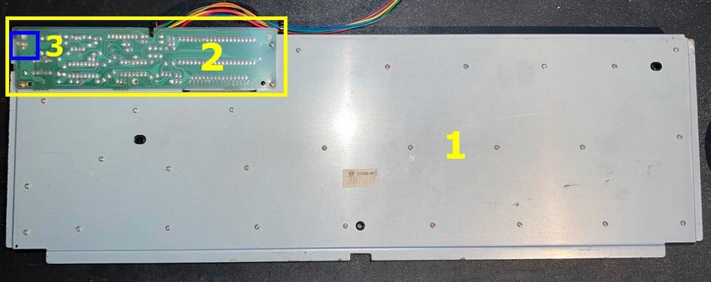
The metal backplate is removed by the following steps:
All the small screws directly screwed to the plate are removed
The three small screws holding the insulating plastic are removed
The last ground screw is removed
The positions of these are shown in the picture below.

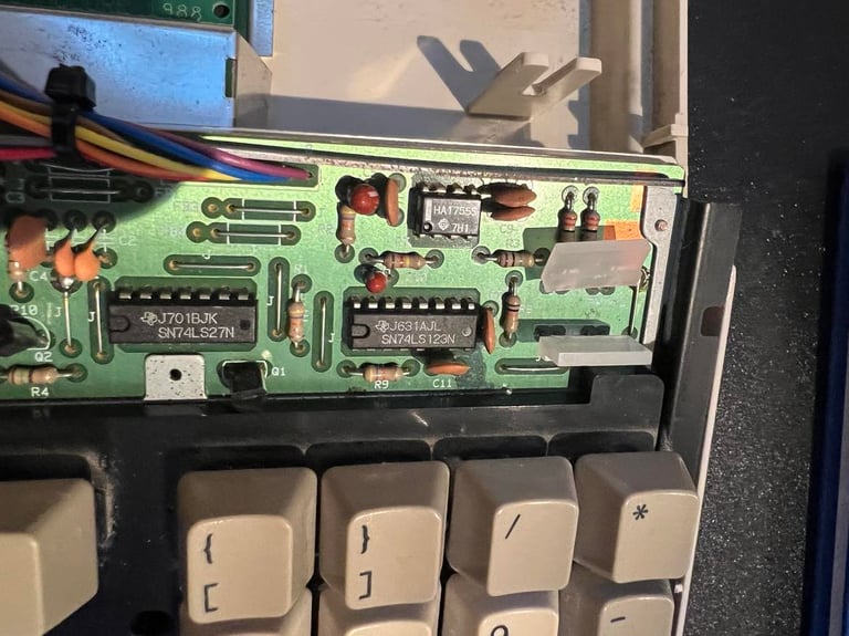
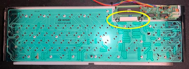
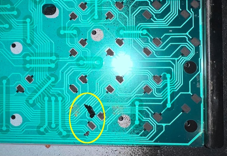
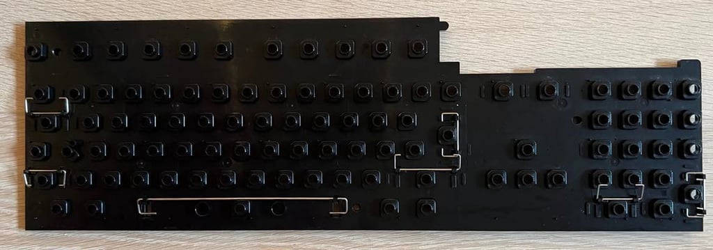
Lifting away the metal plate and the PCB reveals the keyboard membrane. And I see that on the membrane, just below the "0" button, there are some debris from a broken plunger. So that is probably the reason why the "0" is not working. Some of the carbon pads looks a bit worn, but not too much I hope. See pictures below. The membrane is carefully removed from the connecter after the connector is pushed downwards.

The membrane is cleaned very carefully with isopropanol. It is important to not clean the membrane too hard in order to prevent the carbon pads from being destroyed.
Next, the each key is removed individually with a keycap puller. It is not too dirty, but it will be nice to clean the plastic casing and it is necessary to remove the key caps to release the key plungers.

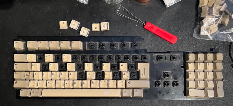
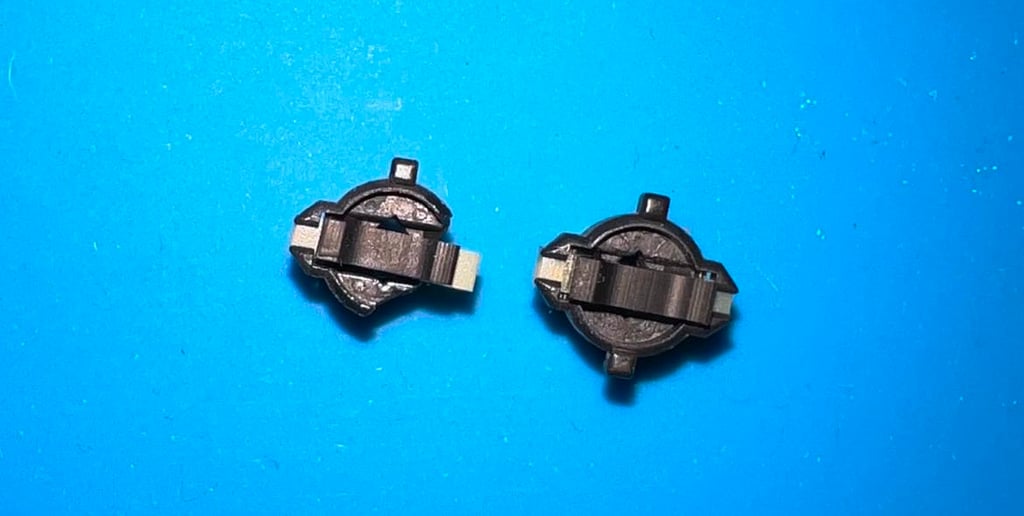
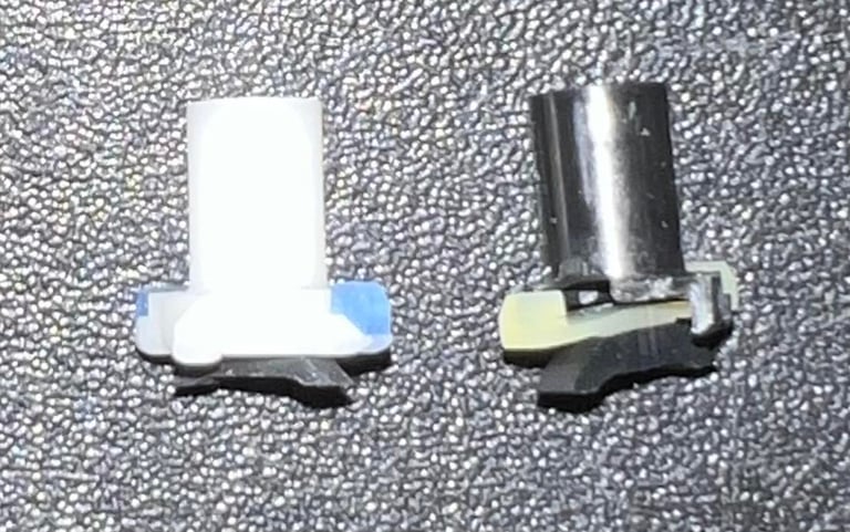
I can not see any immediate problem with the "Enter" key, but the "0" key plunger is obviously broken. In the picture below the "0" plunger is to the left, and the "Enter" plunger is to the right.

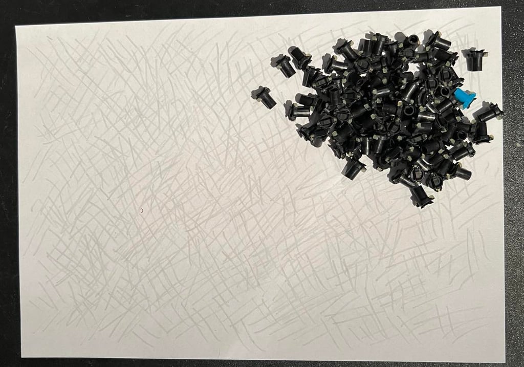
Each plunger is gently wiped on a piece of paper. And in addition all plungers are cleaned with isopropanol on a Q-tip.

The plastic casing is cleaned with mild soap water. And it looks like new afterwards!

All plungers are put back in the plastic casing, and the "0" plunger is replaced with a new. Note that the new plunger is not identical, but it is from an different original Commodore Amiga (but I am not sure which one). Also, the "Enter" plunger is repaired by using the old "0" plunger carbon pad. Hopefully that will work.

There are some corrosion on the keyboard PCB. It is not very severe, but it is removed with some sharp tools. The area is sealed with some solder and nail polish.

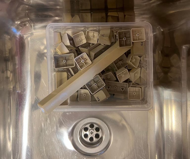
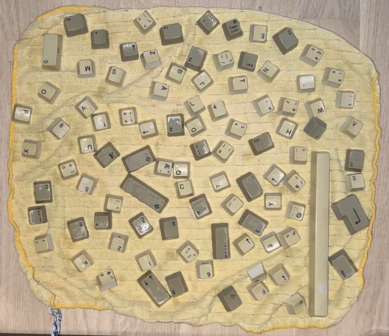
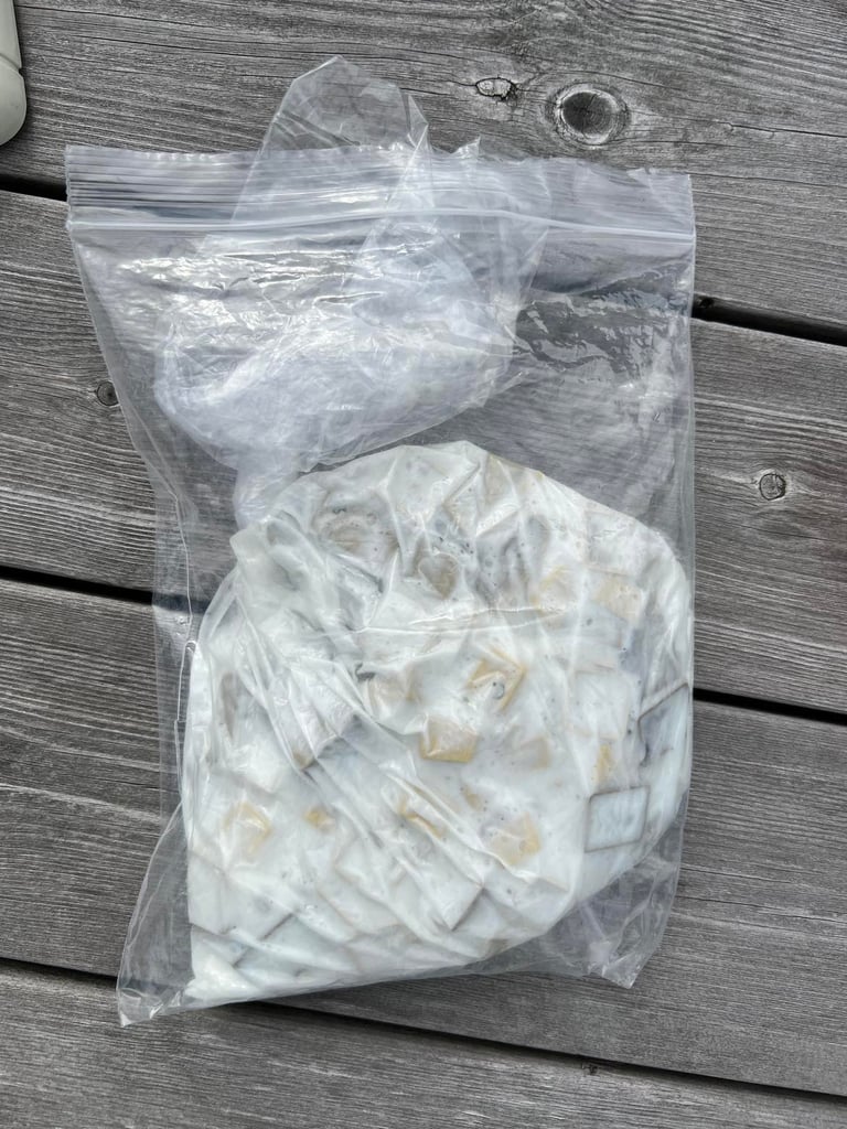
All keys are soaked in soapy water for 12 h and then dried. And since the keys are quite yellowed they are placed in a plastic for about a week.

The bottom metal plate is carefully straightened. It is not 100 % straight, but it is way better than before.
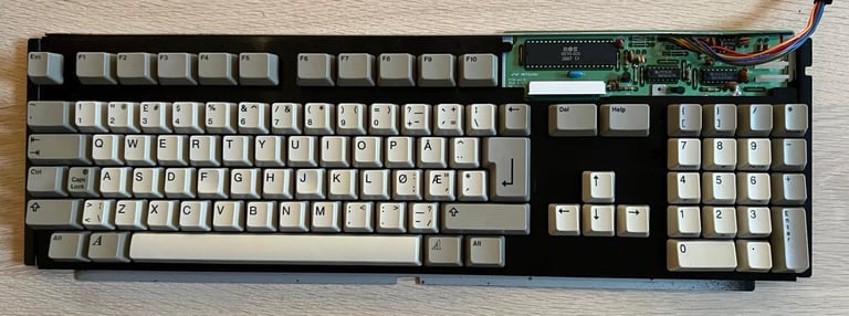
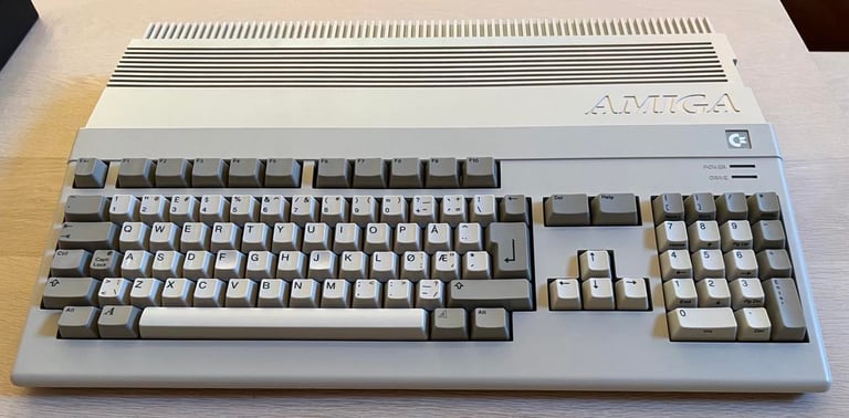
I am very pleased with the result of the keyboard retrobrighting. The keys are more or less back to its original color. The keyboard is assembled and made ready for final testing.
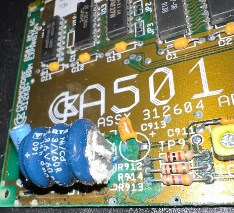
RAM expansion - repair
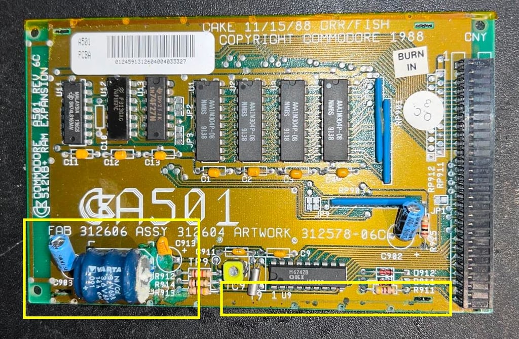
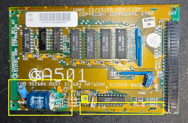
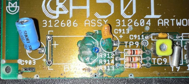
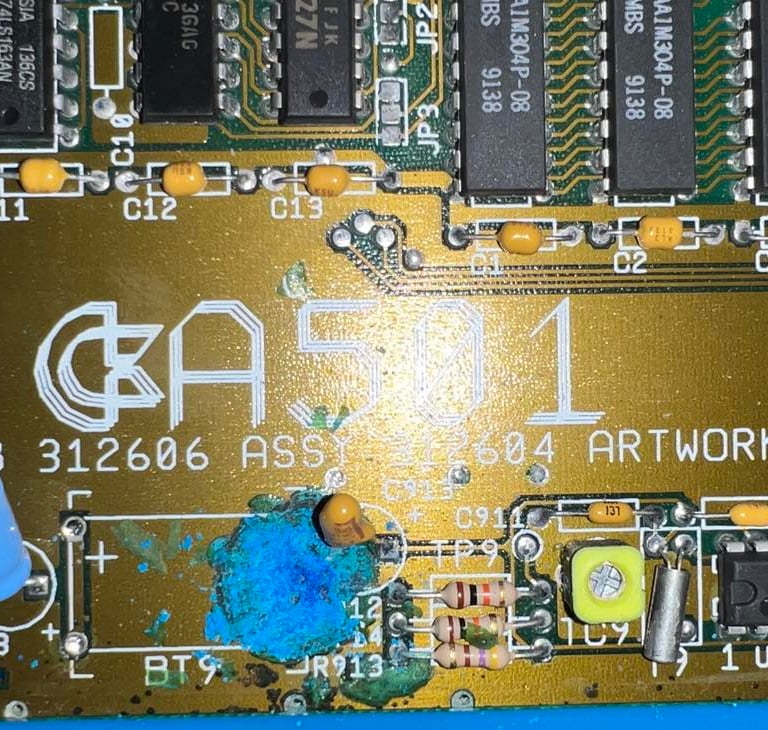
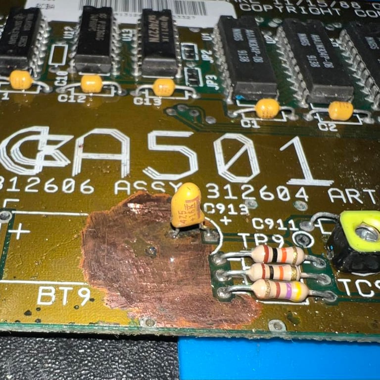
This is an original A501 Rev C 512 kB memory expansion made by Commodore for the Amiga 500 (FAB 312606 Assy 312604 Artwork 312578-06C). As previously mentioned the battery (Varta 3.6 V / 60 mA Ni/Cd) has leaked significantly. This will gradually deteriorate the PCB since the leakage will lead to corrosion which eventually will eat away copper traces/pads and even damage components. So this battery needs to be removed ASAP and all leakage/corrosion must be handled to avoid further deterioration of the PCB. Below is a close-up of the Varta battery leakage.

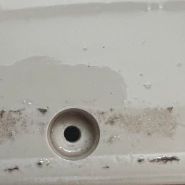
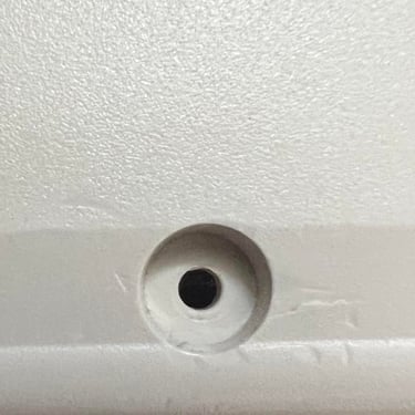
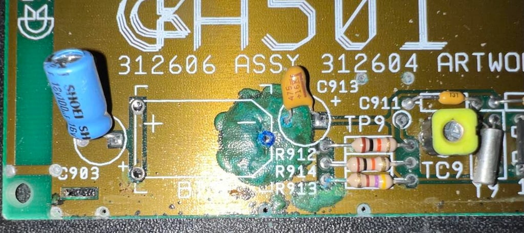
The battery is soldered off the PCB. There are only three solder points holding the battery. This reveals the damage to the PCB. It is not too bad, but I see that I probably need some rework around the tantalum capacitor area.
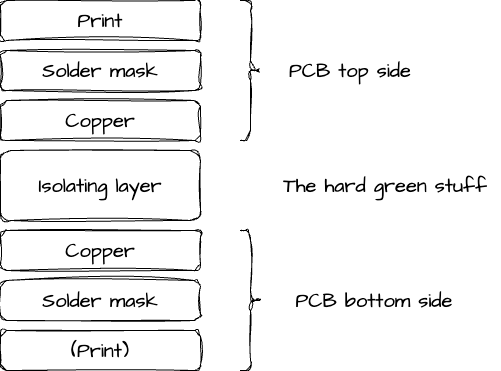
To repair the damaged area it is important to remove "everything". What it means is that when scraping off the corrosion that all layers above the copper is removed. The copper layer should be completely exposed, cleaned and sealed. In the figure below you can see how the PCB is made up of different layers. The print layer and solder mask will be removed first. Then the copper layer is scraped clean from any corrosion, cleaned properly and sealed.

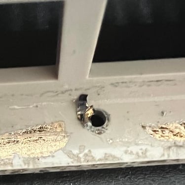
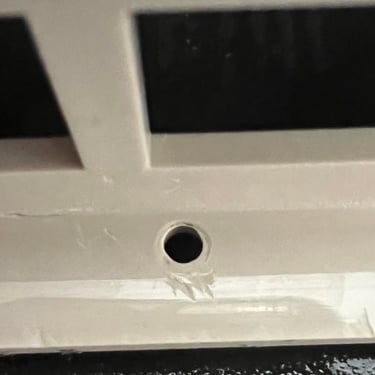
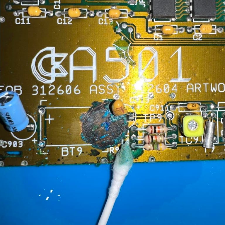
The leakage / corrosion is scraped off using sharp metal tools such as thin flat screwdrivers and needle tools. This is quite time consuming, but I belive all the dangerous corrosion is removed. Finally I use some transparent nail polish to seal the area. The tantalum capacitor is also removed (and eventually replaced) during the process. Below are some pictures from the cleaning process. Click to enlarge.
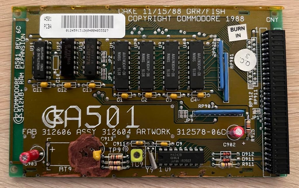
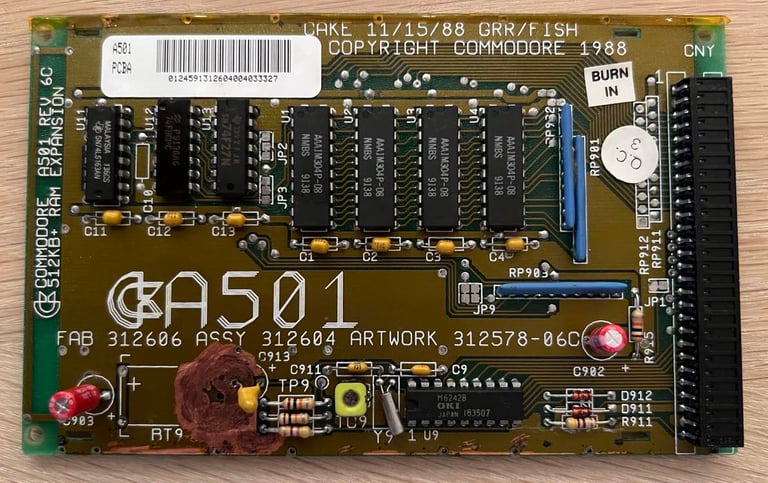
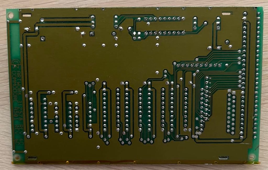
There are two 100 uF 16 V electrolytic capacitors on the PCB. Since these are over 30 years old and likely to be dried up, they are replaced with new capacitors from Wurth Electronics. The both sides of the PCB is also cleaned throughly with isopropanol. Below are pictures of the refurbished A501 512 kB RAM expansion.

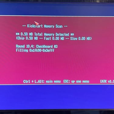
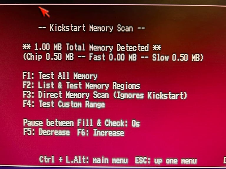
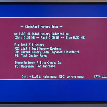
Does it work? To check if the RAM expansion works I connect the card to the A500 and run the Amiga Test Disk memory tool.

And luckily the RAM expansion looks to be ok! The A500 both detect the additional 512 kB and reports a grand total of 1 MB of memory. Also, no memory faults are detected when the memory tools are used.


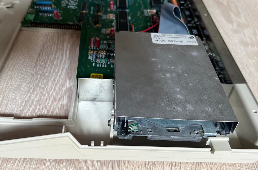
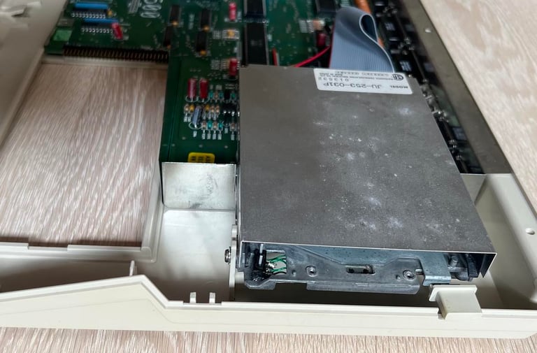
Installing the internal disk drive
As previously mentioned this machine came without an internal disk drive. So, to make the machine "complete", a refurbished internal disk drive from Matsushita is installed (Model JU-253-031P). This drive was previously used in Amiga with the same mainboard revision (Rev A), so this is the kind of drive that could very well be of the same make and version as the original.
As this disk drive is already tested I will wait until the machine is completely assembled before the drive is tested (again).
Testing
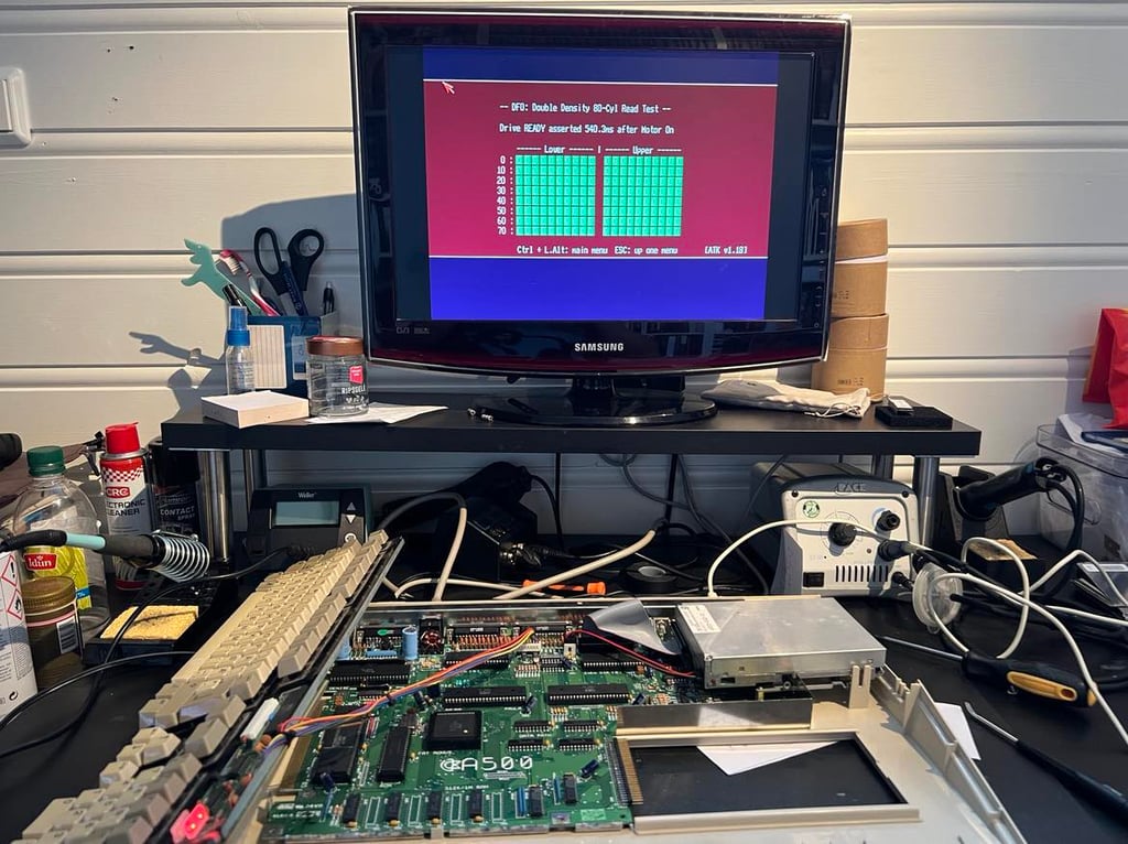
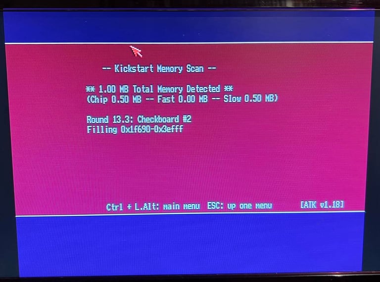
Now it is time for testing the whole machine. All parts such as keyboard, RAM expansion, keyboard and disk drive have been tested in isolation, but now I will try to test "everything". How? Well, I basically to this in two stages:
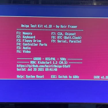
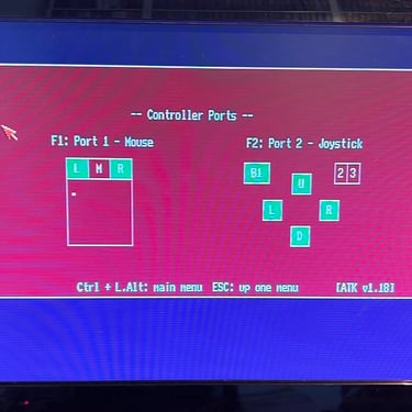
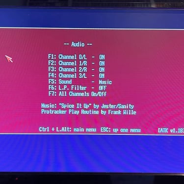
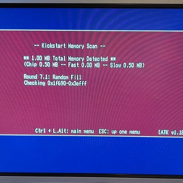
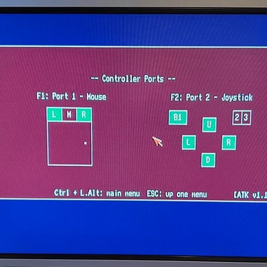
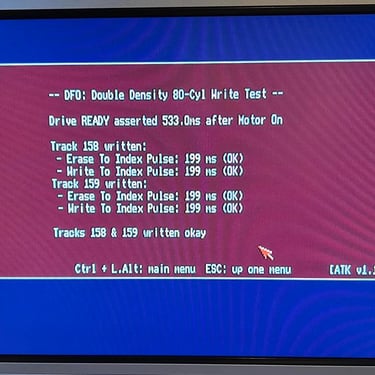
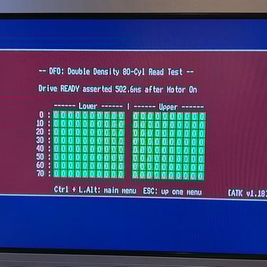
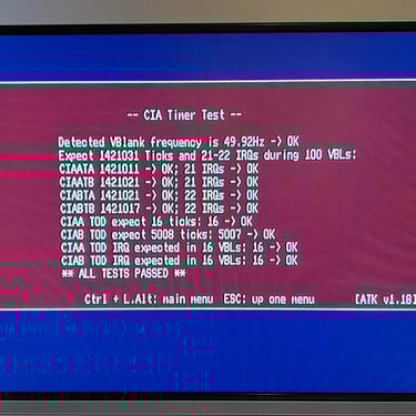
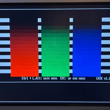
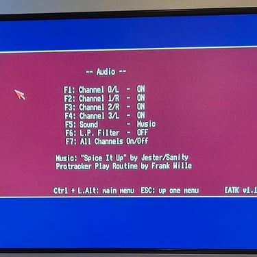
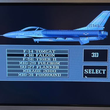
Formal testing with the Amiga Test Kit 1.18 (ATK). This will test most of the basic parts such as memory, floppy drive, video, audio, CIA, mouse, joystick and keyboard.
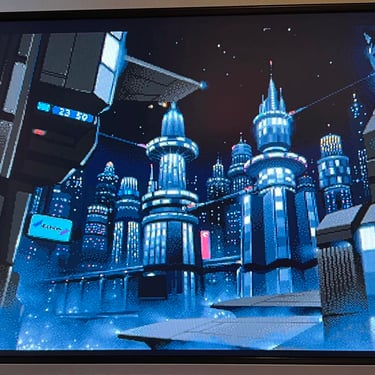
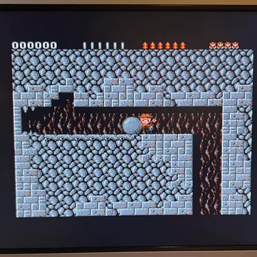
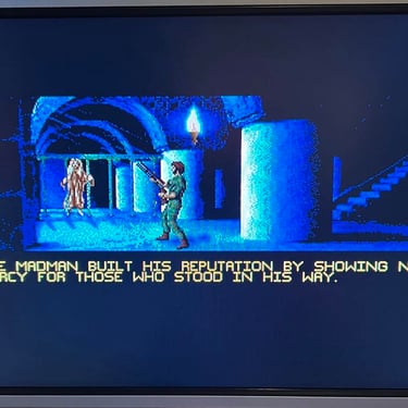
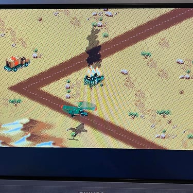
"Real usage" testing. I will basically use the machine playing games, watching and listening to demos and use the machine in regulator operation. This will detect flaws not easily detected with the ATK 1.18.
All tests passes, but I notice two areas which is good to be aware of:
The keyboard works, but some keys needs some more "push" to be detected. This was something I noticed during refurbishing. My theory is that this is not something that can be fixed with cleaning. I would expect that this is a combination of a bit worn out membrane and some rubber plungers with a bit more resistance than optimal. Nevertheless, the keyboard works, but can be changed if it is to be used heavily.
I once noticed that the floppy drive did not register that a disk was wríte enabled. After a drop of electro cleaning spray on the frontmost switch this was fixed, but I think that this switch might need a "splash" of electro spray once in a while for the drive to detect write enabled. No big deal.
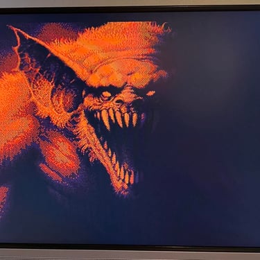
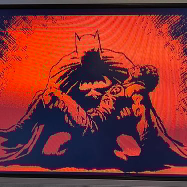
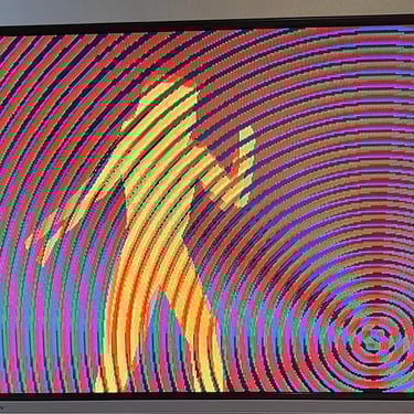
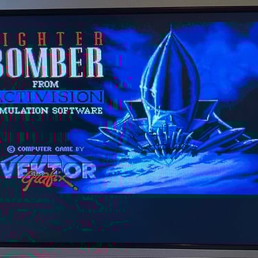
Below is a picture gallery from the final testing. Click to enlarge.


Final result
"A picture worth a thousand words"
Below is a collection of the final result from the refurbishment of this Amiga 500. Hope you like it! Click to enlarge!


Banner picture credits: Ajne01