

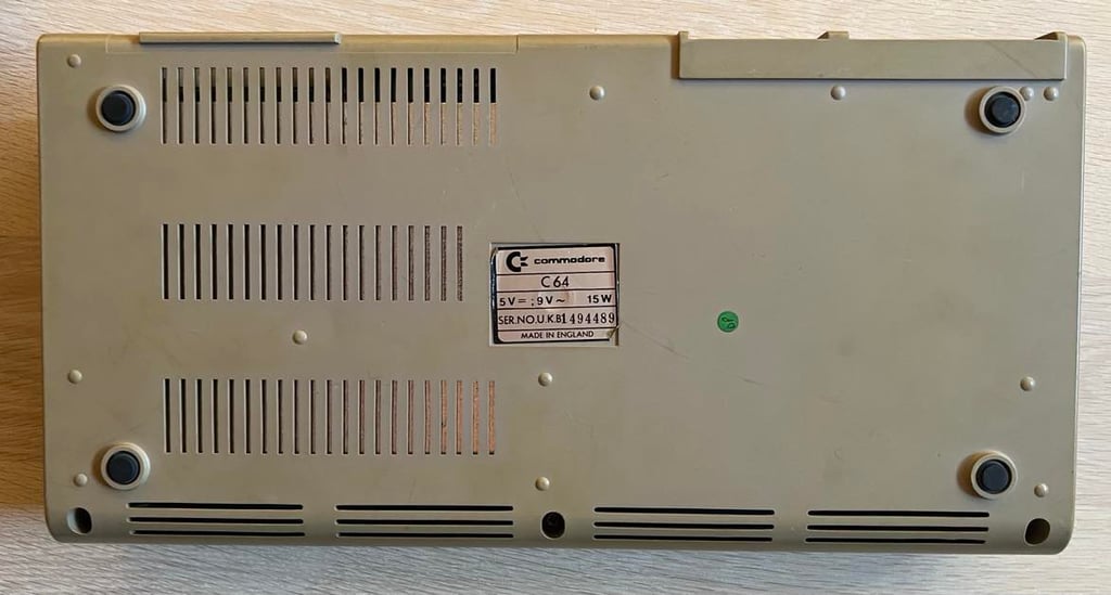
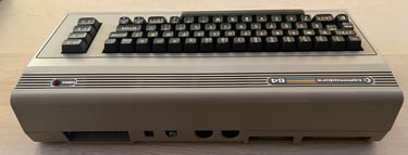
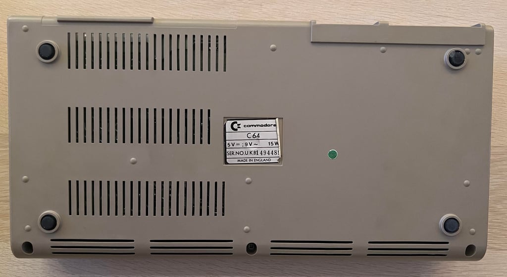
C64 Breadbin
Ser. No. 1494489
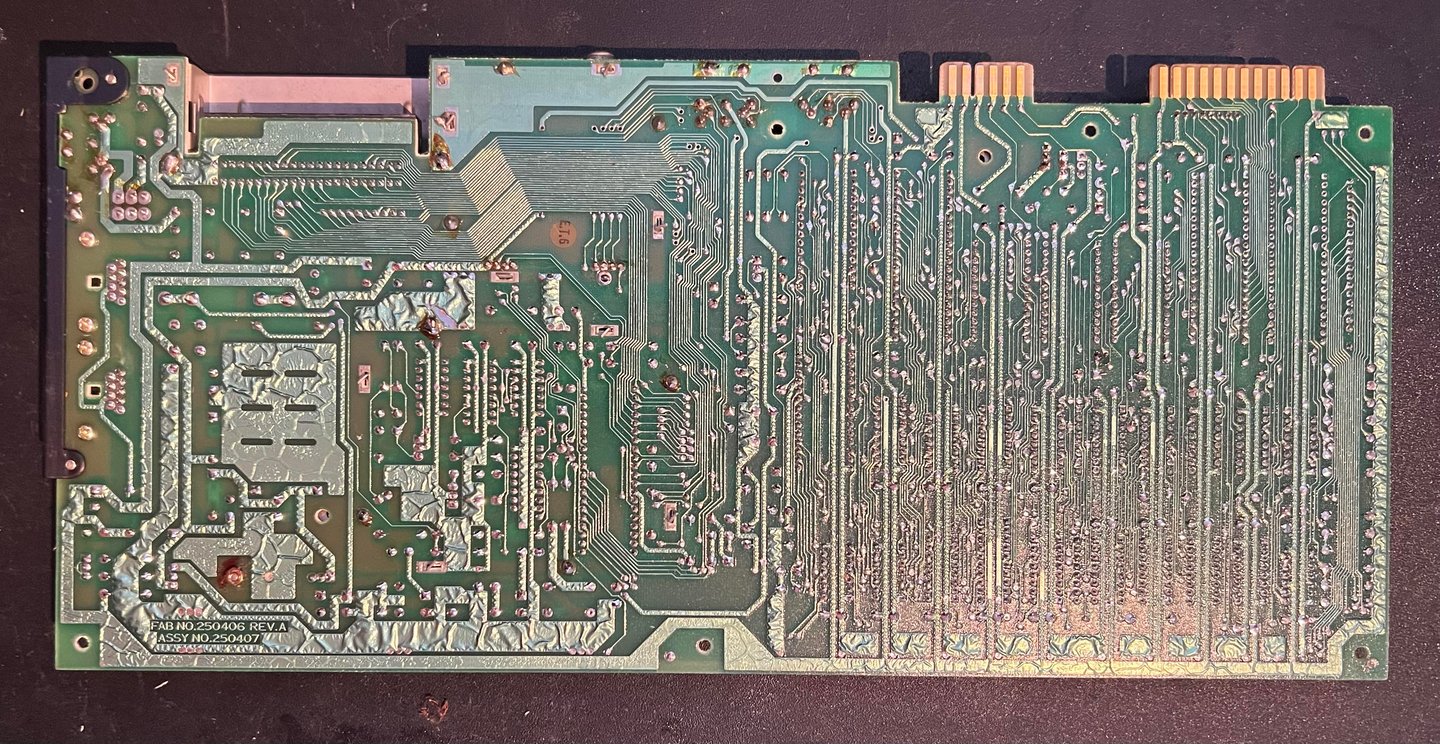
Assy 250407
Artwork 251137 (REV B)
Starting point
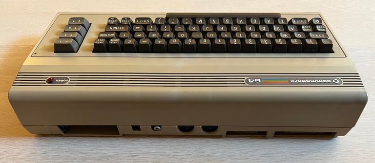
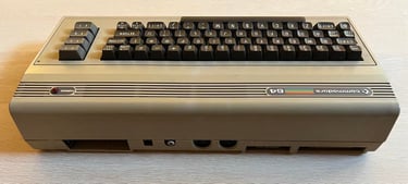
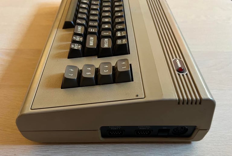
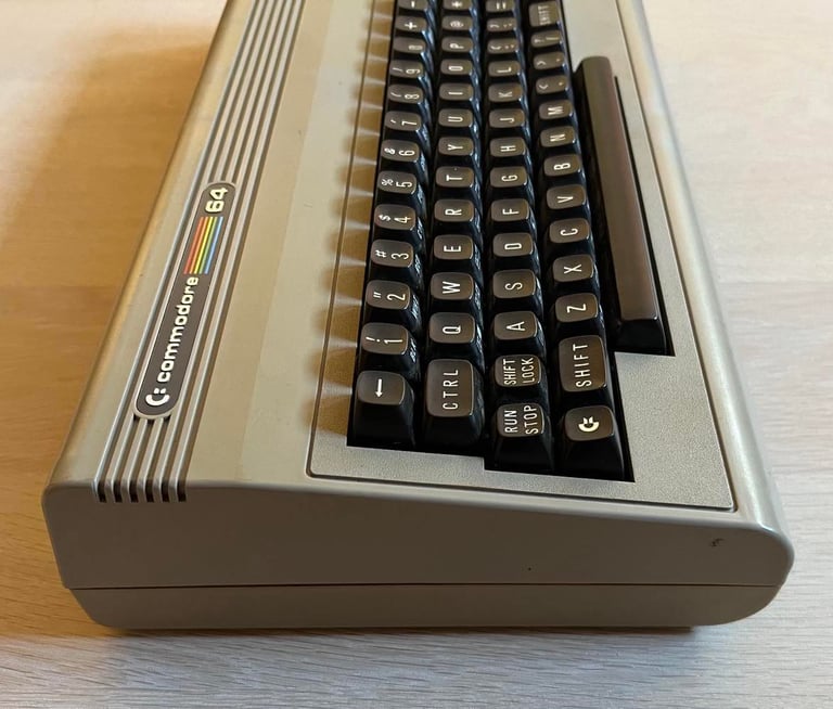
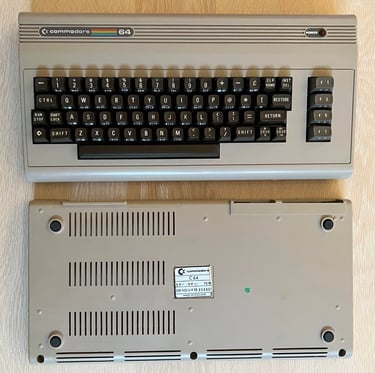
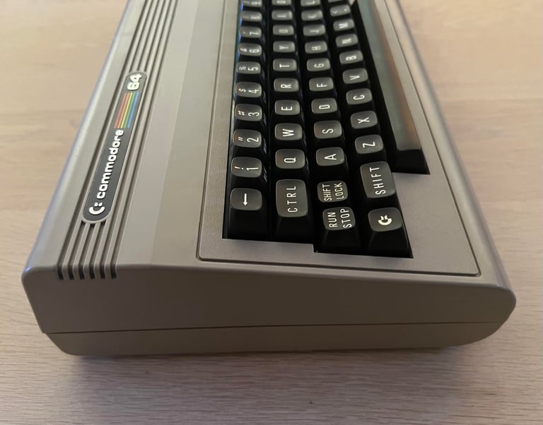
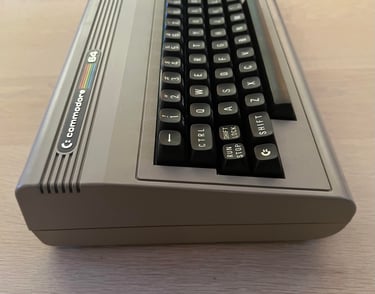
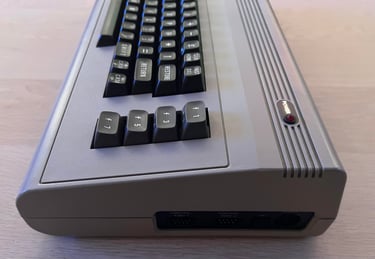
This Commodore 64 breadbin has come for some refurbish. From the outside it looks to be in quite good condition! Yes, it is a bit yellowed and dirty, but other than that it looks to be in pretty good shape. Nice!


Refurbishment plan
The refurbishment plan for this C64 breadbin (several of them in parallell):
- Clean and remove stains from the casing
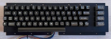
- Clean and restore the keyboard
- Refurbish main board (cleaning, checking, repairing, replacing capacitors and voltage regulators, adding heat sinks etc.)
- Recap RF-modulator
- Verify operation by testing
The plan can be updated during the refurbishment process. Sometimes I discover areas that needs special attention.
Opens it up...
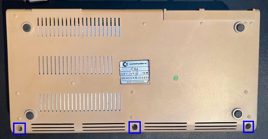
The Commodore 64 breadbin casing is made from a top- and bottom cover which are held together by three wood screws at the bottom. These three screws are removed and the casing can be opened.

The top cover is carefully lifted to an angle of about 30 degrees and then gently wiggled out. It is important to do this carefully so you don´t risk breaking the brittle plastic clips at the rear of the top cover. When the top cover is lifted to a 90 degrees angle the interior is revealed. And - lo and behold - I have never seen a more pristine looking RF-shield! I looks almost brand new! Am I the first one to do service on this machine?

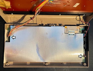
And now I see another small miracle: all of the small thin plastic clip at the rear are there! This is very uncommon as these break very easily. I see that one of the clips is a bit loose, but I think I can manage to fix that with a drop of super glue. Regarding the RF-shield this will be removed eventually (the owner will have it as souvenir) since the necessity of this is gone in modern years. The only thing the RF-shield does now is to encapsulate heat which could reduce the lifetime of the chips.
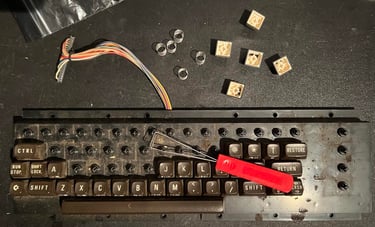
The keyboard- and LED connector are removed (see arrows) and the top cover and keyboard is lifted away. At the same time the RF-shield is partly removed to that the mainboard is exposed in its full glory.

The keyboard is detached from the top cover by removing the eight screws - see picture below.
Exterior casing
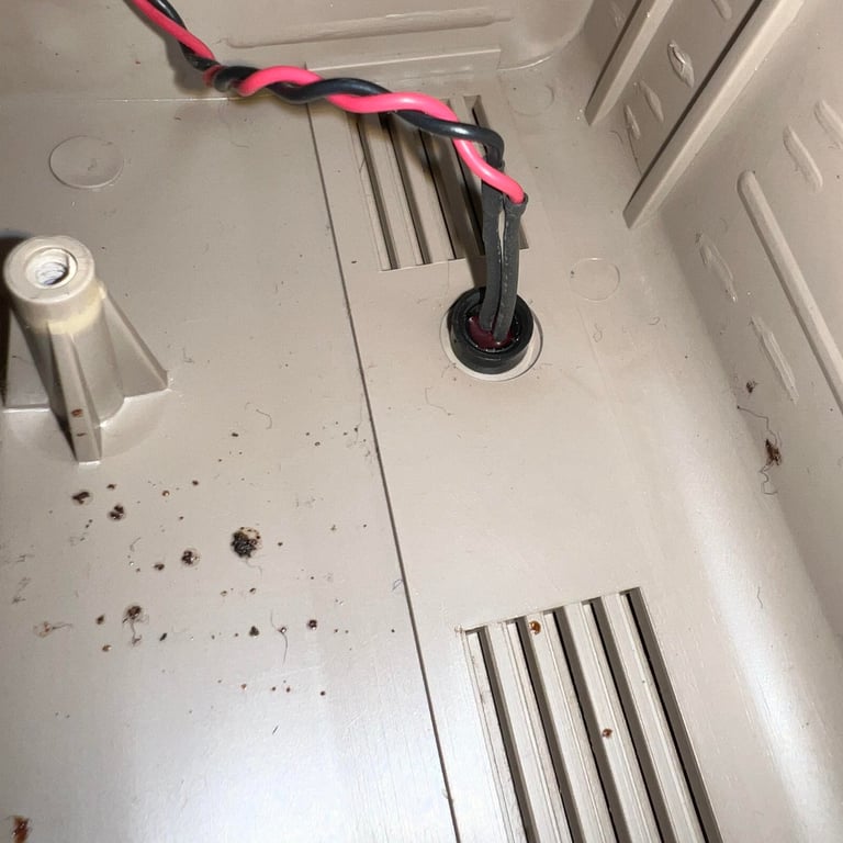
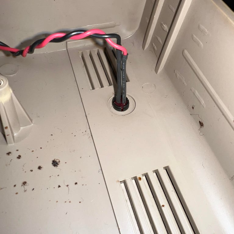
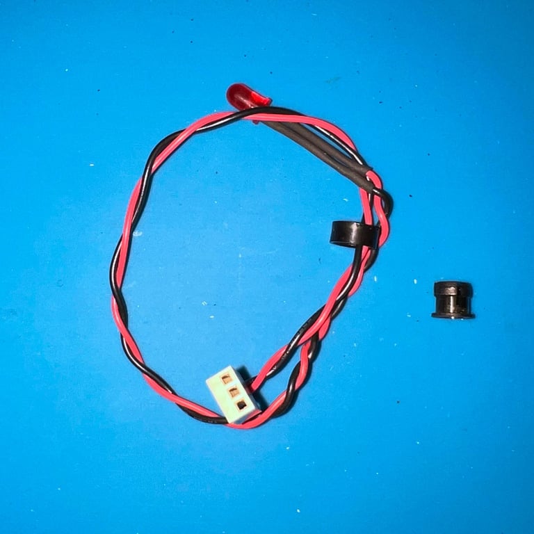
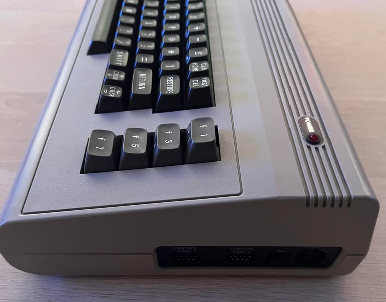
The top- and bottom cover are quite dirty and yellowed, but they are otherwise in good condition as far as I can see. Some minor scratches, but no severe cracks or damage as far as I can see. Before the top cover is cleaned the LED is removed. You can argue that this is not strictly necessary, but I plan to clean this very thoroughly and also do some retrobright so I will try to get all non-casing parts out of the way. To remove is very easy, but here is a quick "howto":
Remove the small plastic ring from the inside of the cover (the ring holds the plastic LED clip on place)
With a firm push press the LED from the outside towards the inside of the cover. It should pop-out quite easy.
Carefully pry the small plastic clip from the inside towards the outside of the cover. This can be brittle so it is good to be a bit careful.
Below are some pictures from the LED removal.
Both metal badges ("COMMODORE 64" and "POWER") are removed by using some hot hair from a hair drying while carefully using a small scalpel to lift them away.
The top cover is placed in mild soap water for about 12 hours to dissolve all the grease (the top is way more susceptible to grease than the bottom) while the bottom cover is cleaned with a combination of soap water, glass cleaning spray and isopropanol.
After cleaning the top- and bottom cover are retrobrighted for about 10 hours using a combination of hydroperoxide cream and UV-light.
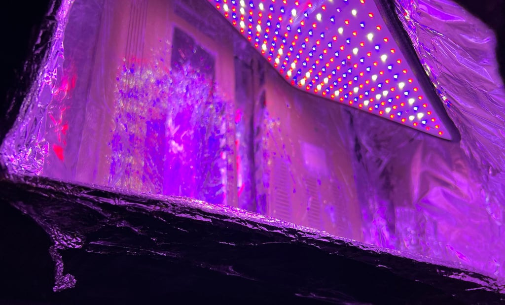
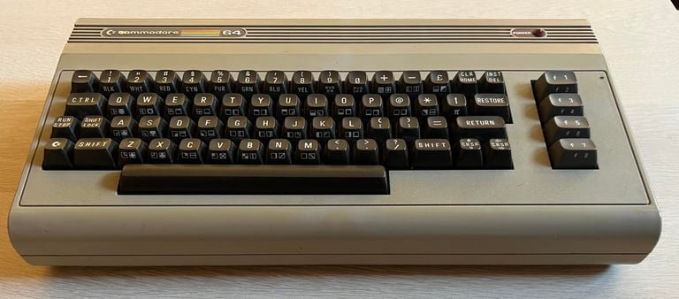
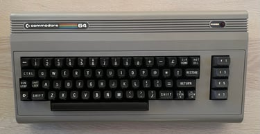
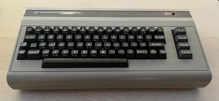
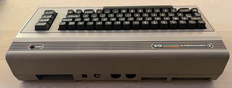
The end result after cleaning and retrobrighting looks very good. See picture below - with the cleaned keyboard in place! Looks new?!

Keyboard
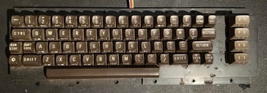
The keyboard appears to be in good condition, but there is quite some dirt and grease. But this is normal after 40 years of duty.

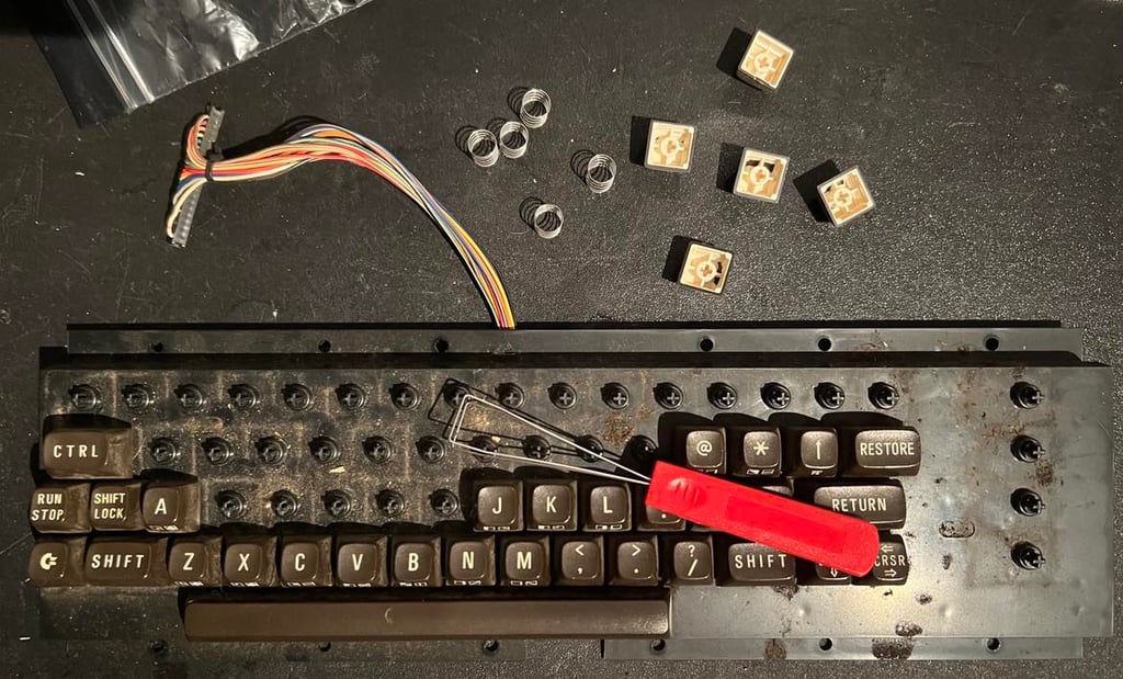
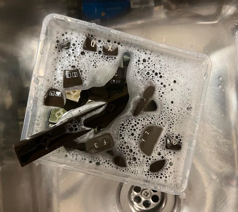
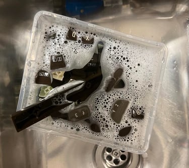
All the keys are carefully removed with a key puller. I strongly recommend using a key puller to avoid breaking the plungers below the keys. There is a spring beneath each key - but note that the spring beneath the spacebar is larger than the rest. So it is a good idea to keep this spring separate.
The keys are placed in a box of soap water and some glass cleaning liquid for about 12 hours. This is a gentle way of removing old grease and fat.
To remove the SHIFT-LOCK key the two wires are desoldered first. Then the key is pushed from the backside of the keyboard towards the front. The key will "pop out".

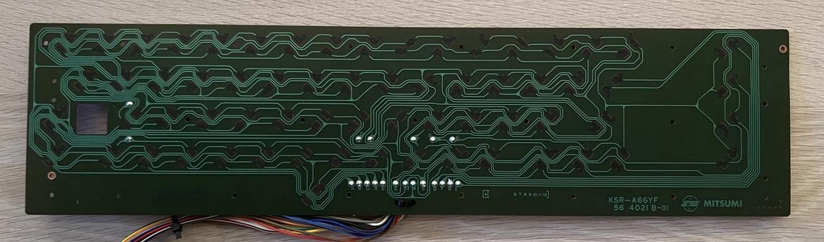
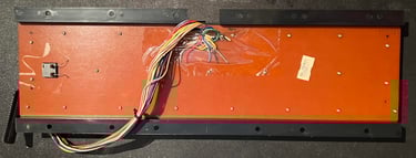
All the small screws on the back are removed - revealing the keyboard PCB. This is the common KSR-A66YF PCB from Mitsumi. The PCB is cleaned carefully with some isopropanol on a paper tissue. Below is a picture of the keyboard PCB after cleaning. Looks as new!
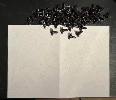
Each plunger is cleaned individually by gently rubbing on a clean piece of paper. In my experience this is the most careful way of cleaning the plungers. If it turns out that some plungers don´t work I will try to clean with some isopropanol.

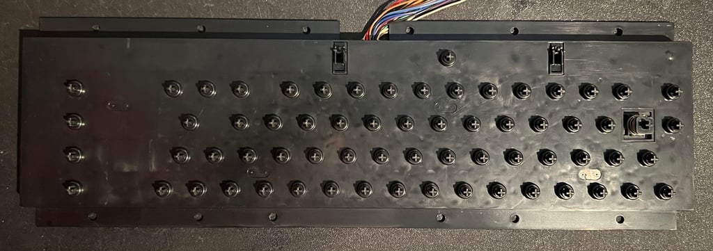
The plungers are placed back into the clean plastic casing - one by one.
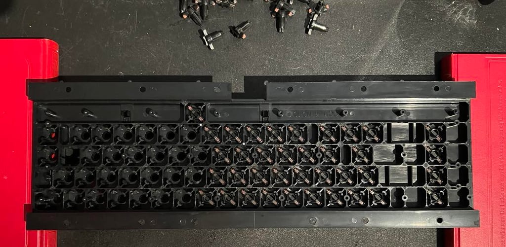
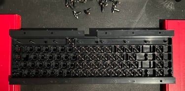
Keyboard PCB is put back in and the SHIFT-LOCK key is soldered in place. The plastic casing and plungers looks brand new now (!).


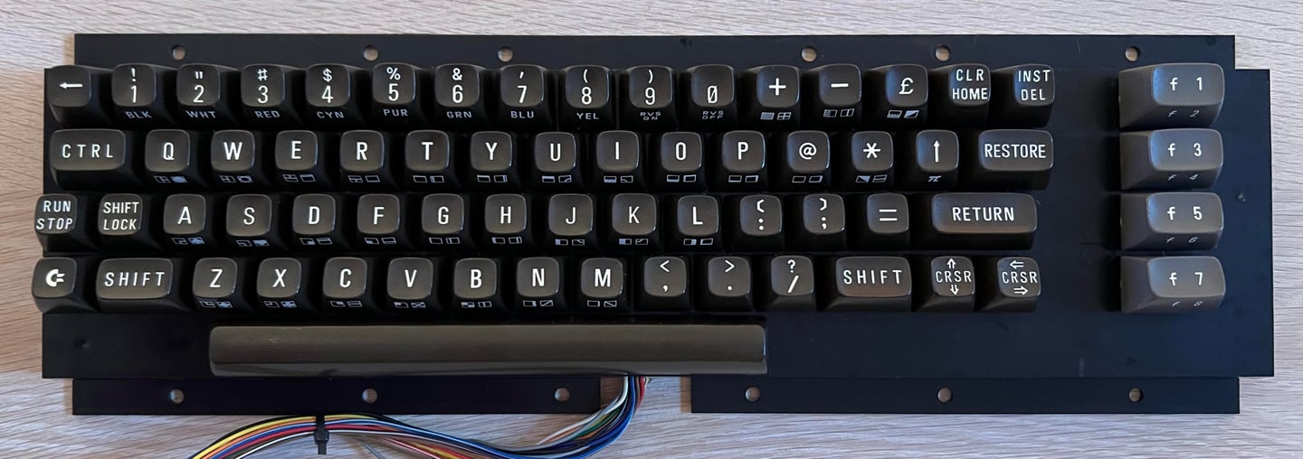
After all keys have been cleaned and dried they are put back on the plungers. The keyboard looks as new I think. I am reluctant to retrobright the keys since the old breadbin keys are likely so be damaged using hydroperoxide. The best thing is to sunbright the keyboard, but the weather in Stavanger doesn´t allow for that at the moment... perhaps the owner can put the keyboard in the sun next summer:-)
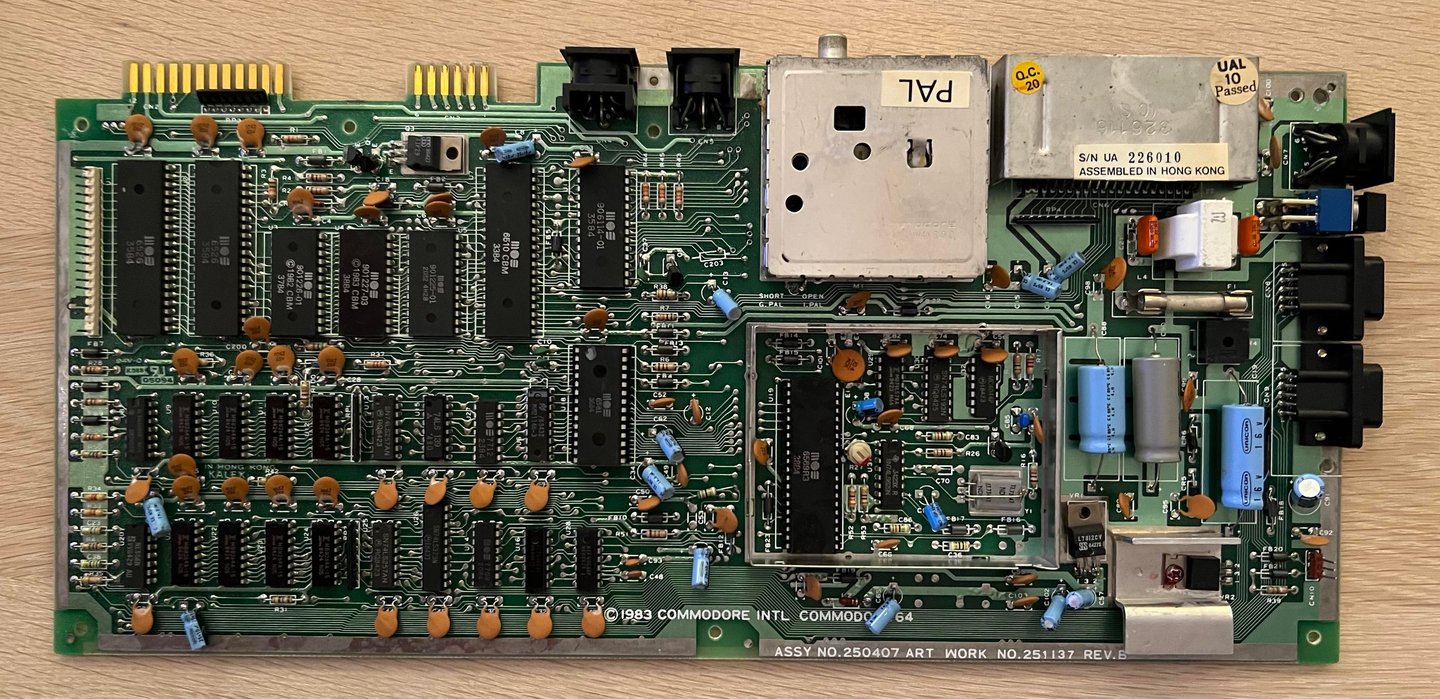
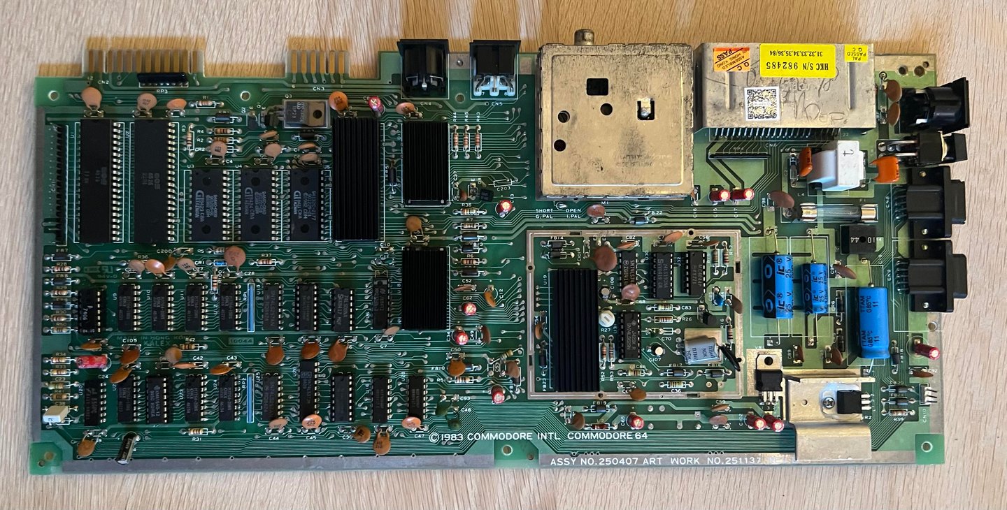
Mainboard
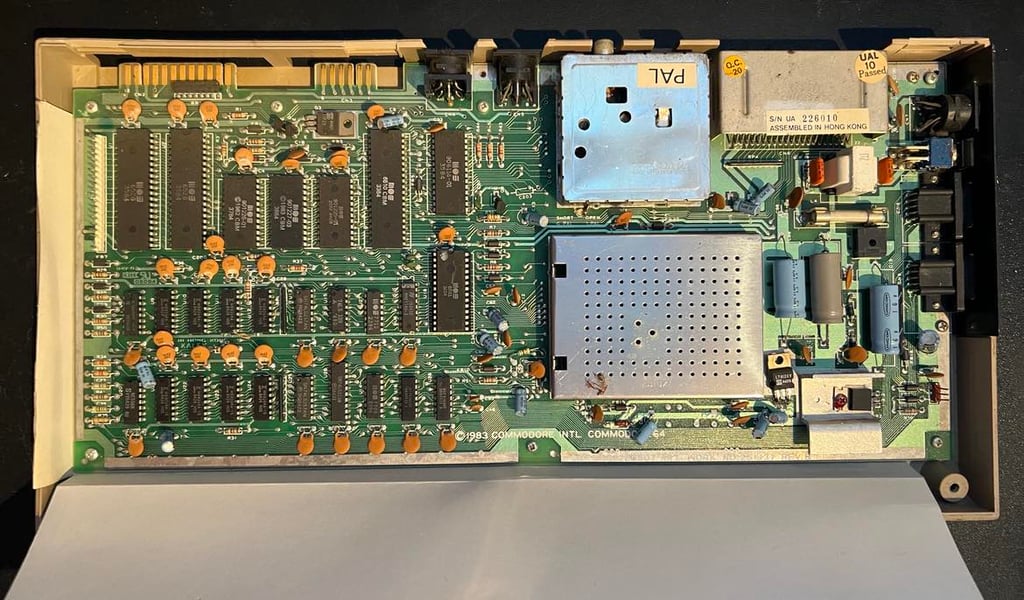
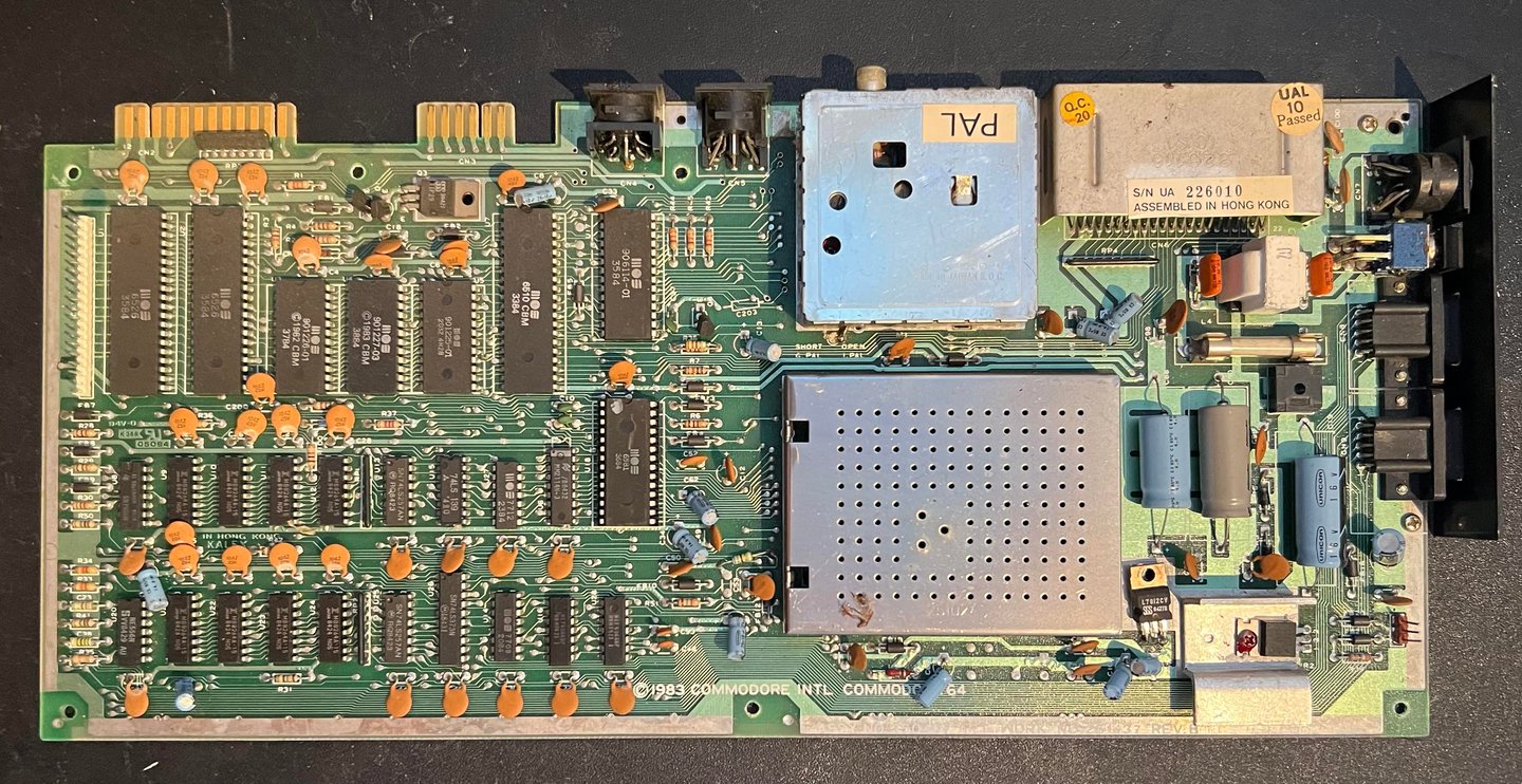
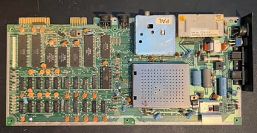
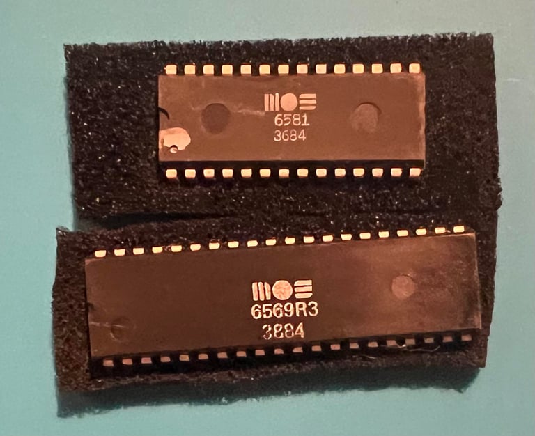
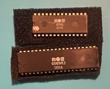
This is an "Assy 250407 / Artwork 251137 (Rev B)" long mainboard with the good old 6581 SID, 6510 CPU and 6569 VIC-II chipset.
Visual inspection
I can not see any sign of corrosion, ripped traces, bulging capacitors or rework. It is a bit dirty, so I will clean it later. Only the MOS 6569 VIC-II and the MOS 6581 SID chip are socketed. In the table below the main chips are listed (before refurbishment - some may be changed during repair if required).
The custom MOS chips are made in period from week 33 to 37 in 1984. The Fujitsu RAM chips are a bit earlier; week 24 same year. I think we can assume that this Commodore 64 was manufactured some time in the autumn of 1984. There are two MOS chips also used as "glue logic" - the MOS 7712 and MOS 7709. These chips are notorious for failing unfortunately so should be replaced with modern replacements.
Initial testing
Before turning the machine on for the first time it is good practice to check for short circuit at the +5 VDC and 9 VAC power line. The easiest place to test this is at the user port (see the HOWTO - Checking the C64 voltages article for the position of the +5VDC and 9 VAC rails). Also, the MOS 6581 SID chip is removed. The SID chip is not required for the Commodore 64 to start - and we avoid damaging it if the machine turns out to be broken.
Powering on the machine shows a... BLACK SCREEN. There is a video signal, but signal payload is only black. Well, this is not unusual, but it means that this machine needs repair.
Checking the voltages
For the machine to operate flawlessly all voltage levels needs to be present and within acceptable range. As previously mentioned the HOWTO - Checking the C64 voltages can be used to understand which voltages needs to be present and the purpose of them. In the table below all the voltages which are measured are listed. Note that this table will be updated after repair and refurbished to verify that everything is ok after.
All the voltages are fine - so there are no indication that the voltages are causing the black screen issue.
Dead test cartridge
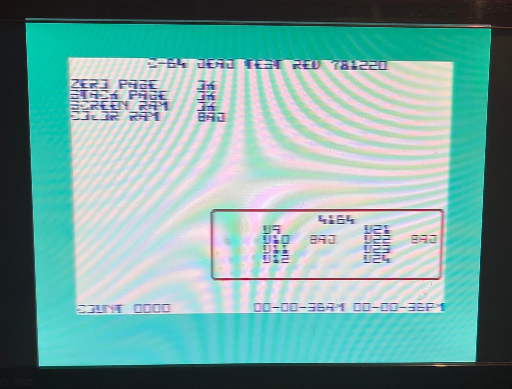
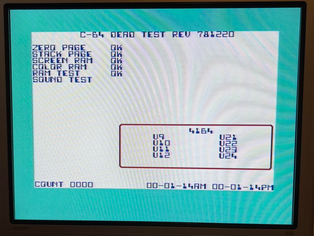
The dead test cartridge can be a good tool for fault finding. It doesn´t need ROM- or CIA chips to give valuable results. And the dead test gives some interesting things! In the picture below the result from the dead test cartridge is show. And I note the following:
The VIC-II chip seems to work. At least it produce a video signal.
The 2xCIA seems also to work. The AM and PM clocks appears to be updated while the dead test is running.
The dead test cartridge use it owns character font. But the characters appears to be partly corrupted.
The dead test stops after "COLOR RAM" (BAD) and U10 and U22 says BAD. U10 and U22 are RAM chips.
Checking for varm ICs
A faulty IC will often get hot - very hot. So it can be a quick way to identify a faulty chip. But I can´t feel anything unusual. Some of the chips get warm, but nothing which feels unormal.
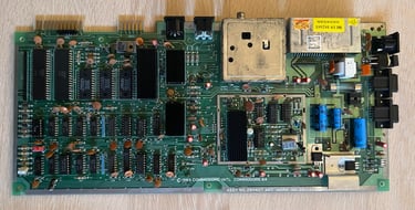
Cleaning the mainboard
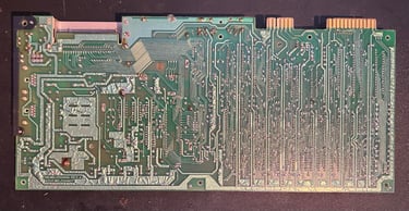
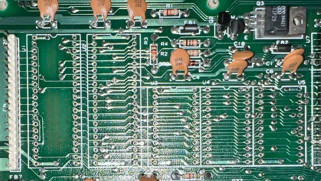
Before continuing fault finding the mainboard is cleaned properly. The socked chips (VIC-II and SID) and the fuse are removed and the mainboard is washed thoroughly with luke warm dishwasher soap and a soft paint brush. The water in Norway is both quite clean and soft so there are very little residue after this operation. But it is a good idea to soak the mainboard in isopropanol afterwards. This will make sure that all the water evaporate faster. The mainboard is left to dry upside down for about 18 hours. Below are some pictures after the cleaning - it looks very nice.

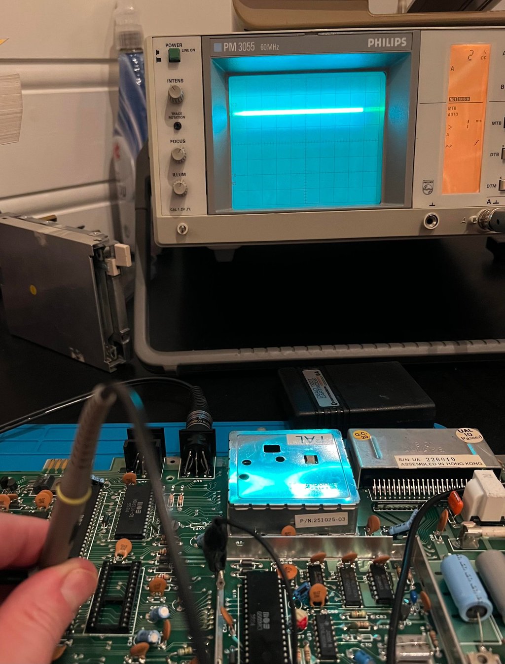
Checking for faults with the oscilloscope
With the oscilloscope I check several of the signals to see if I can find anything suspicious. In the table below (which will be updated as the checking continues) shows what I find.
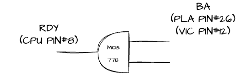
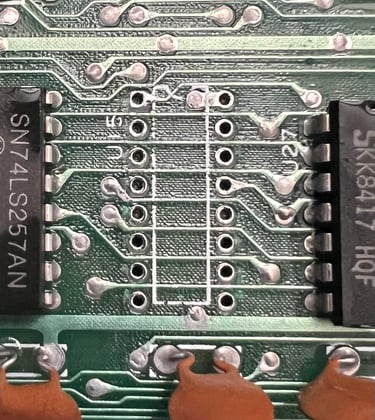
As the table shows there are some areas which needs investigation. The first thing I investigate further is the RDY (CPU), BA (PLA) and BA (VIC-II). The reason for choosing these first is that these three signals are interconnected through the MOS 7712 AND-gate. Below is a picture of measuring the weird +4V signal at pin #9 on the MOS 7712 (U27).

Both the MOS7712 and the PLA are notorious for failing - and the signals are connected as the schematics below shows.

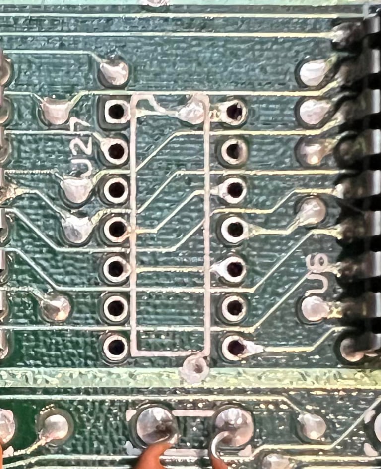
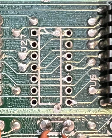
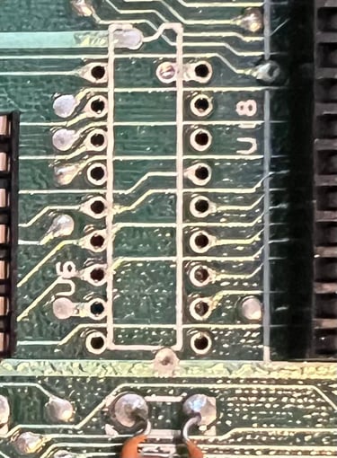
The MOS7712 (U27) is desoldered and replaced with a socket and a new 74LS080 chip. Result is still a black screen. Next, the PLA (U17) is desoldered and replaced with socket and a known working PLA. Result... still a black screen. Well, such are these things! The VIC-II is also replaced with a known good working without any success. Below are some pictures from the desoldering. No traces were lifted during desoldering.

Although these chips were not bad it is not a bad idea to have these chips in sockets. Both the PLA and the MOX 77xx are known to fail frequently, and to have these chips socketed can be very handy when replacing these.
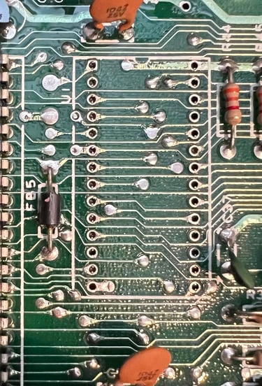
Next, I think it might be something wrong with the glue logic surrounding the RAM chips? And one candidate which could case problem is the MOS 7712 (U14) which sits between the VIC-II and the RAM chips (via the 7406). See schematics below. Note that in this schematics the MOS 7712 is known as 74LS258.
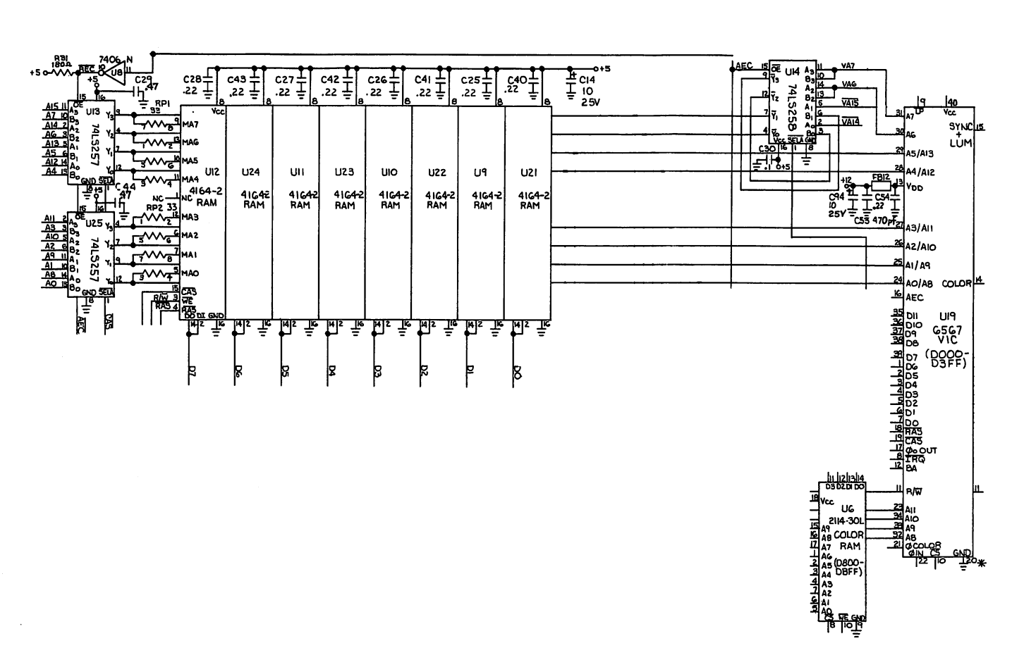
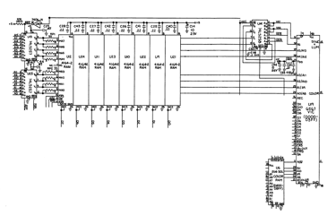
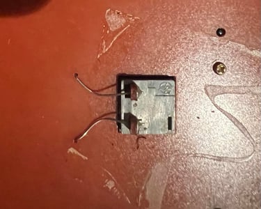
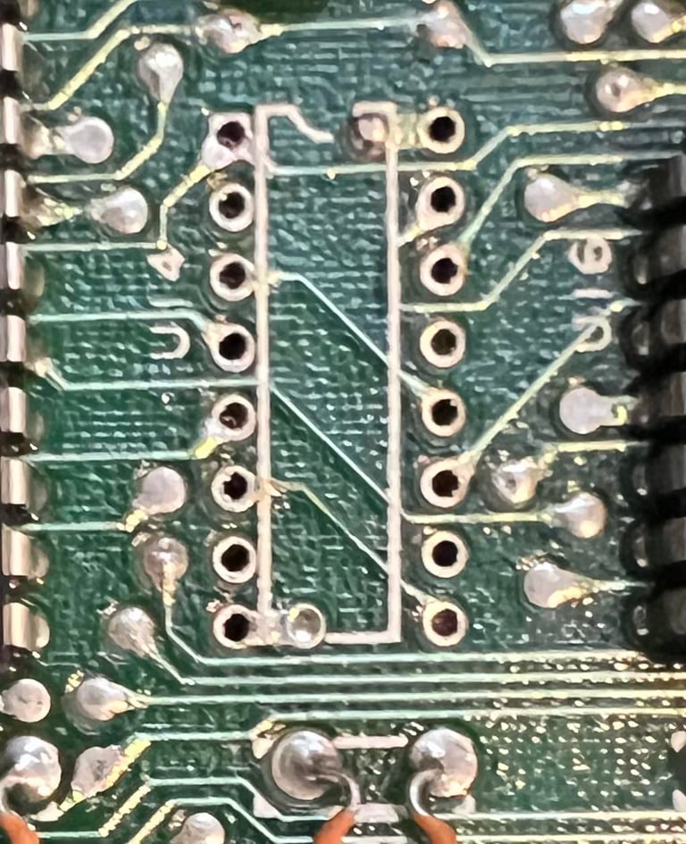
The MOS 7712 (U14) is desoldered and replaced with a socket and a new 74LS258. Did it help...? No... still black screen! Below is a picture of the desoldered MOS 7712 - no pads or traces were lifted during desoldering. Note that this was also a "good thing". Even if the MOS 7712 works having this in a socket is very handy since this chip are likely to fail due old age.

Using the oscilloscope I probe several of the chips without seeing anything suspicious - the "only" thing I see is the BA and /IRQ stuck HIGH and LOW accordingly. Before delving into the schematics study I decide to desolder both the color RAM (U6) and CPU (U7). Unfortunately I forgot to take a picture of the desoldered CPU but I guarantee that no traces or pads were lifted. I don´t really think it is a problem with either the CPU or the color RAM, but I would like to rule it out. Below is a picture of the desoldered colorram.

Perhaps no surprise but the CPU chip is fine. No problem there. I do not have a spare 2114 Color RAM chip, but when the IC is removed and the Commodore 64 is started the test sequence with the dead test cartridge is identical - only difference is that the colors are flashing bright since there are no color RAM. See video below.

BA, /IRQ and RDY not stuck
I have previously said that the Bus Available (BA), Ready (RDY) and Interrupt (/IRQ) were stuck. Well, that is only true when the Dead Test Cartridge is not installed - and actually makes perfectly sense since the test program is running (at least for some time). But that also means that is was probably a red herring following this track. My theory now is that these circuits work as they should, but that there is something wrong in the RAM domain. Why? Well, when the Dead Test Cartridge is not installed it is likely that the Kernal tries to reach some RAM address where the RAM is corrupt - or point to a wrong memory address. This could cause the machine to crash. The same theory applies when the Dead Test Cartridge is installed. When the program tries to write in the Color RAM address range ($D800) the program crashes.
Removing the CIA#1, CIA#2, 3 x ROM chips
To try to allocate the fault both the CIA #1 and #2 are removed. Also, the the BASIC-, Kernal- and Character ROM are removed. Why? The dead test cartridge can operate without these chips so in order to rule these out as faulty I think it is a good thing to just get them out of the way. And it also quite nice to have these chips socketed anyhow.
Below is a picture of the mainboard with these chips are desoldered. No traces or pads lifted.

Result after the removal of these chips is that the dead test still show the same "COLOR RAM BAD". But I also notice one thing also; the font is partly corrupted like some of the bits are missing. The way the dead test cartridge work is that after RAM check (from $0000 - $1000) a character font is downloaded from an area > $E000 to "low memory". This point me in a direction that there is something wrong with the RAM chips or the RAM glue logic.
Checking for RAM chip fault - or glue logic fault
In the schematics presented earlier there are other glue logic chips (e.g. 7406, 74LS258 etc.) in addition to the RAM chips. After removing and checking all of these it turns out that one of the RAM chips are bad! Is this the fault? A new known working RAM chip is installed - but the result is: only flashing from the dead test. This tells me that there are something more obscure with this mainboard which needs investigation.
Changing the mainboard
It will probably take several weeks to find the fault on this mainboard (since I only do this hobby after work and family) so together with the owner of the machine we agree on using another identical mainboard from another Commodore 64 breadbin which have been repaired - but are missing the SID- and CPU chip. So the refurbishment process will now continue with this "new" motherboard.
The list of chips in the new mainboard are listed below. Note that in this list the CPU and the SID will be changed since these are marginal.
Also, the list of measured voltages on the new mainboard are listed below. This table will be updated after the refurbish is complete.
Mainboard - continued
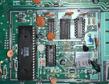
Replacing the voltage regulators
There are two voltage regulators on the mainboard supplying +12 VDC and +5VDC. How these voltages are used can be studied in detail in the HOWTO article "Checking C64 voltages". But a short summary is that these two voltage regulators are used to power the SID, VIC-II, clock- and audio circuits. Old voltage regulators can fail - and if they fail the output voltage can increase above acceptable tolerances which can damage the ICs such as SID and VIC-II.
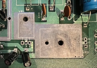
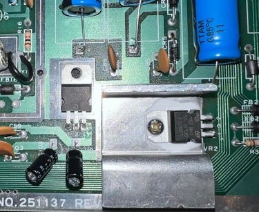
The 7805 (+5VDC) regulator is mounted on a heat sink, but the 7812 (+12VDC) is not - this is normal for the Commodore 64. Both voltage regulators are desoldered without any damage to traces or pads. See picture below.

It is good practice to add some heat paste between the back of the 7805 regulator and the PCB. Also, when fastening the screw and bolt it is not wise to tighten it too hard.

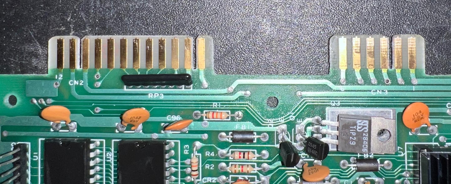
Cleaning the user- and datasette port
After 40 years the user- and datasette port connectors are oxidized and dirty. This can prevent flawless operation e.g. when loading games from tape. To clean these connector a normal rubber eraser is used first. This will gently remove most of the old grease. Note, it is not recommended to use a glass fibre pen for this operation - you could cause damage to the connector traces. Finally the connectors are cleaned thoroughly with isopropanol and Q-tips, and sprayed with electro cleaner. Below is a picture of the user- and dataport after cleaning. Only the top of the mainboard PCB is shown, but both sides of the connectors are cleaned the same way.
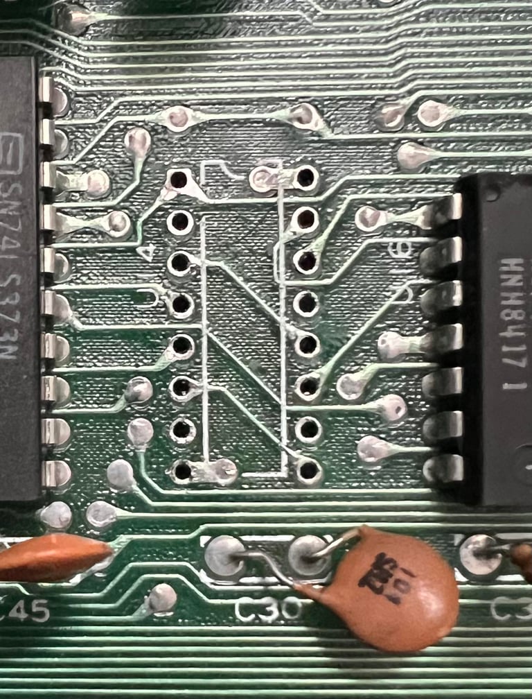
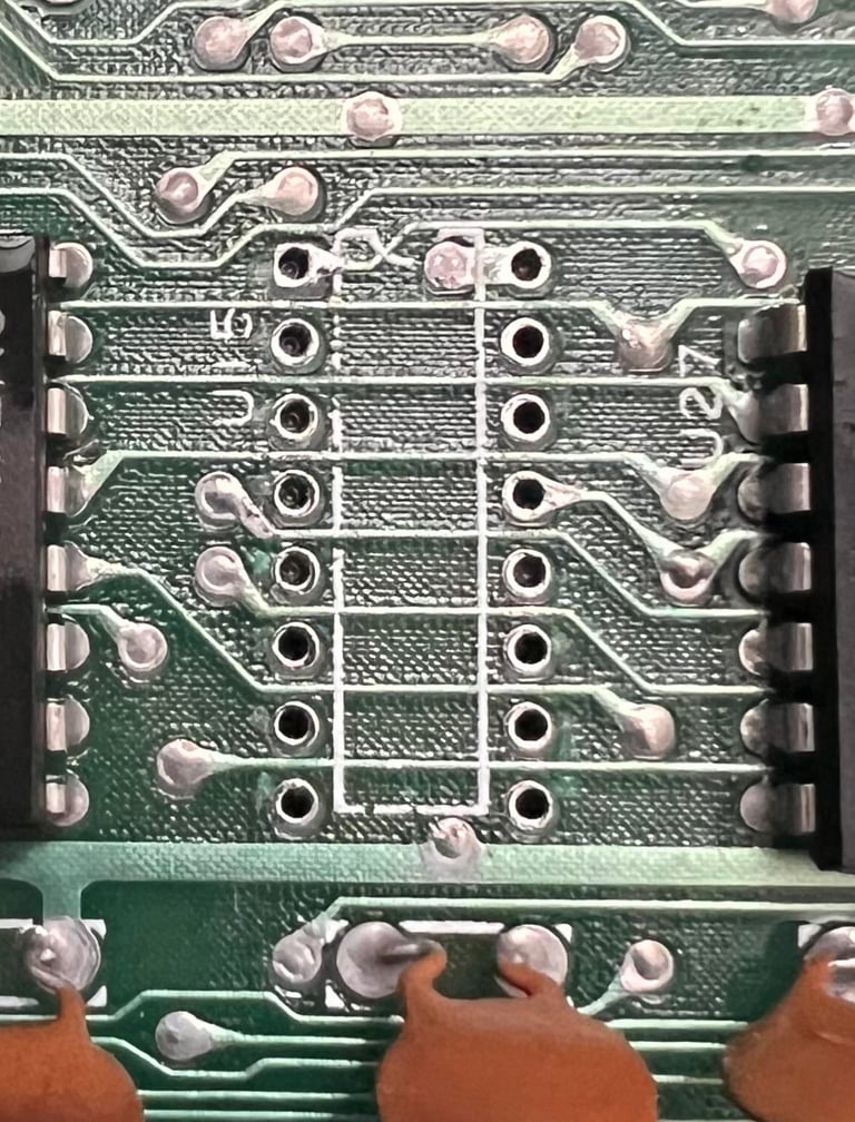
Replacing the MOS 7711 (U15) and MOS 7709 (U14)
The MOS 7711 and MOS 7709 are part of the "glue logic" in the machine, but unfortunately the these chips fail quite often due to old age. The good thing is that there are good replacements available since this chips are nothing else than normal 74LS139 (MOS 7711) and 74LS258 (MOS 7709). So these chips would be replaced anyway - but the replacement does not help anything on the fault. It is still there. No pads or traces were lifted during desoldering (see pictures below).

Removing the VIC-II RF_shield
One of the most important factors which can damage a chip is excessive heat. Therefore it is wise to remove as much of the heat as possible from the mainboard. Heatsinks will be placed on the chip later, but first the VIC-II metal housing is removed. This metal casing was originally meant to filter in/out RF noise, but the only thing it does in modern time is to encapsulate heat. So the metal housing is desoldered completely from the mainboard. Note that on later revision of the Commodore 64 mainboard these metal casings are not used at all.

Replacing the electrolytic capacitors and adding heatsinks - Mainboard
The electrolytic capacitors are old - probably around 40 years. So it is good practice to replace all of these 17 capacitors with new quality capacitors. In addition heat sinks are placed on the most crucial custom MOS chips:
MOS 6510 CPU
MOS 6581 SID
MOS 6569R3 VIC-II
MOS 906114-01 PLA
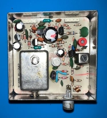
Replacing the electrolytic capacitors - RF Modulator
There are only four electrolytic capacitors in this original Commodore RF-modulator (P/N 251025-03) To replace these capacitors the RF-modulator needs to be desoldered from the mainboard which is not trivial. It is by no means impossible, but you need to be patient and very careful to not damage the pins or pads/traces on either the mainboard or the RF-modulator PCB. For information on how I do this please check "HOWTO-Desolder the RF-modulator".
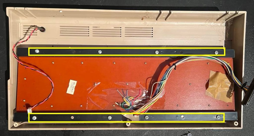
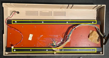
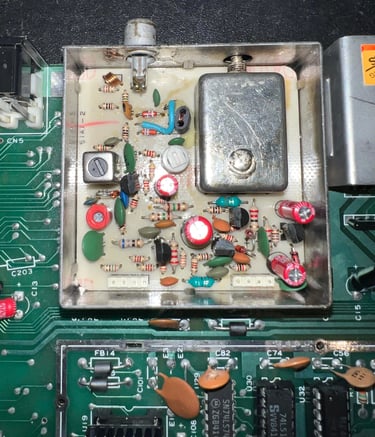
The process of desoldering the RF-modulator is successful. No damage to traces or pads. See yellow squares in the pictures below.
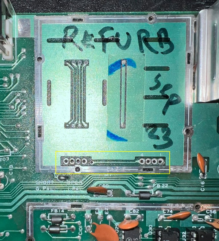
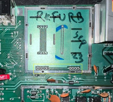
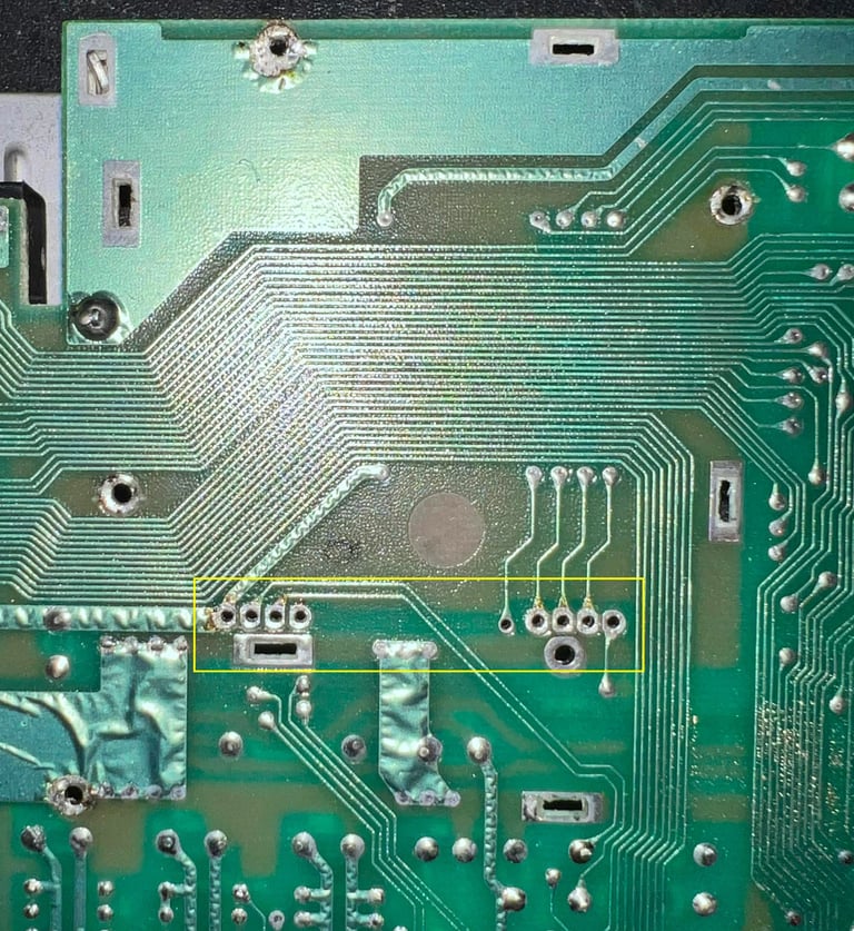
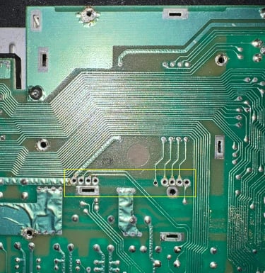
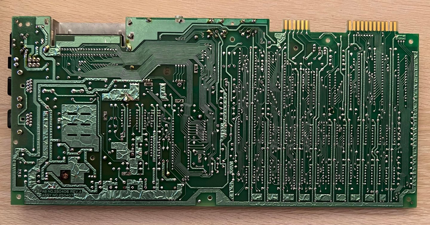
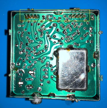
No damage was made to the RF-modulator either in the process. Below are pictures of the desoldered RF-modulator before the recap. And I know it is very nerdy, but I think it is very cool that Commodore has their logo on the backside of the PCB (see arrows).
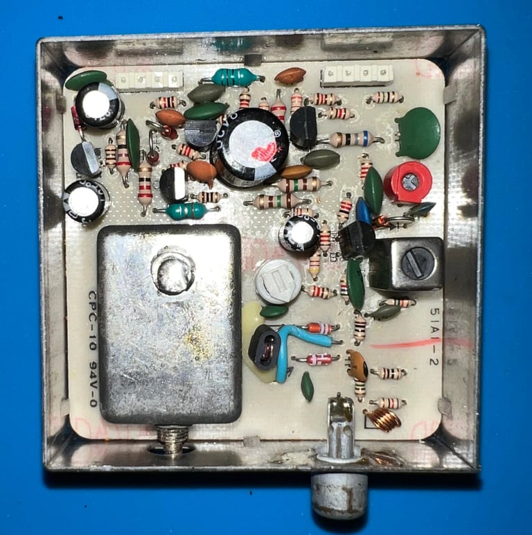

The old electrolytic capacitors are desoldered and removed, and four new quality capacitors are installed. Then the whole RF-modulator are soldered back to the mainboard.

Testing
Proof is in the pudding - does it work?
Testing is done through two main stages:
Testing the basic functionality and chips
Testing by using the machine playing demos, games etc. accessed by both floppy and datasette to verify correct operation
Basic functionality and chips
First test is done using the Dead Test Cartridge. This test doesn´t test all the functionality of the Commodore 64, but it does test the basic functionality of the major chips such as the CIA #1/2, CPU, VIC-II, PLA, RAM and SID. As the picture shows below the test is passed.

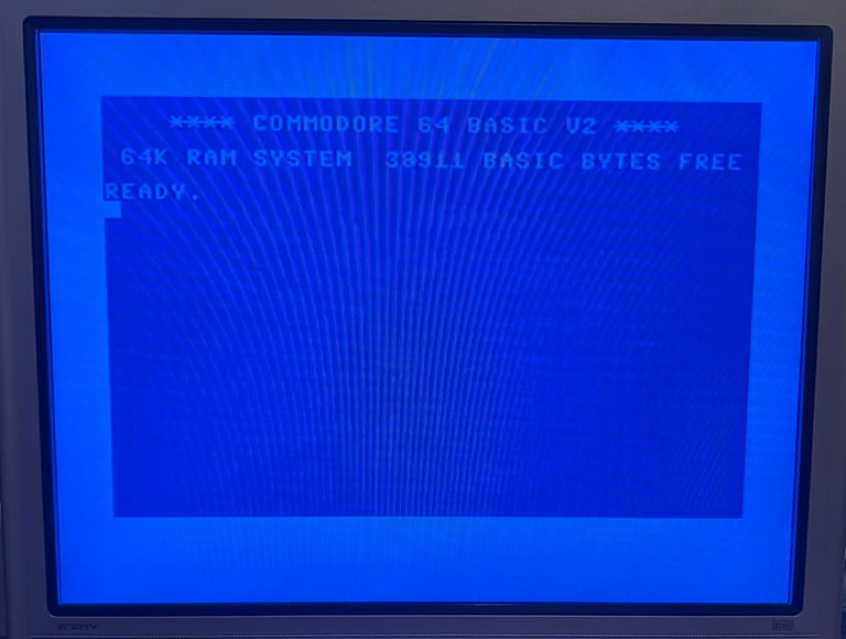
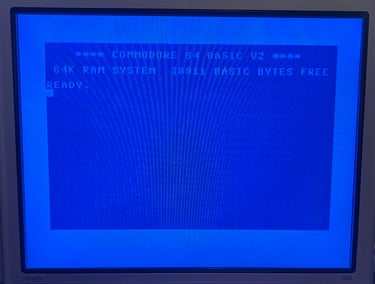
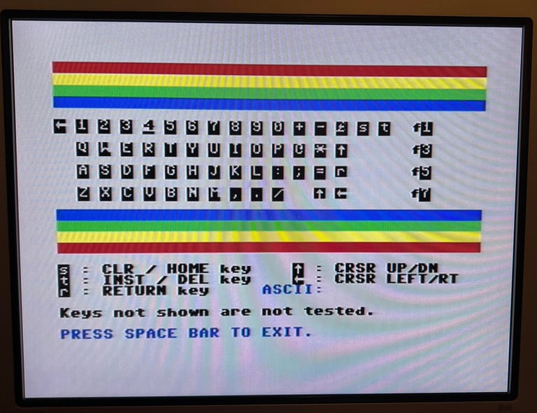
Next test is to power the Commodore 64 to the blue boot up screen and also check the keyboard to make sure all keys works as they should. The test is passed; all keys works and 38911 BASIC Bytes Free.
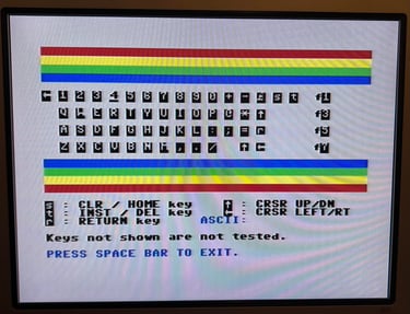
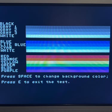
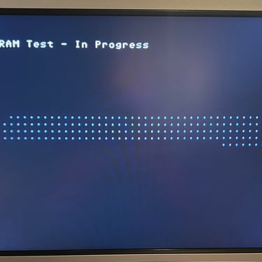
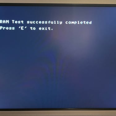
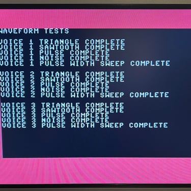
The basic functions of the VIC-II, SID and RAM is tested with 64 Doctor. Note that this is to be considered as basic functionality - more advanced (?) functionality such as sprite handling / collision detection / advanced audio will be tested later. But the basic tests pass without any detected faults (click to enlarge).
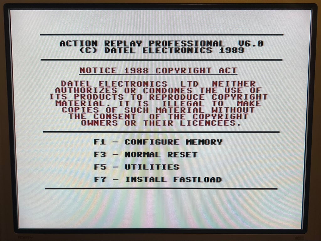
Last basic check before moving to more extensive testing is checking the cartridge. This is done by using the Action Replay VI. Result is that the test is passed.
Extended testing
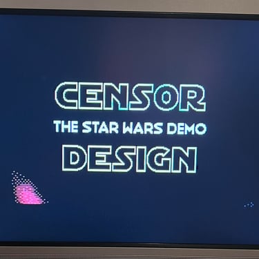
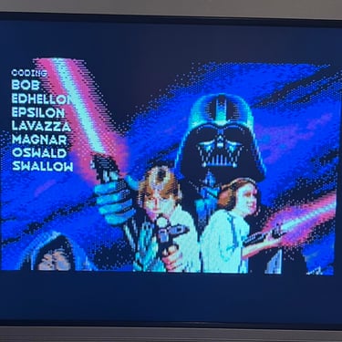
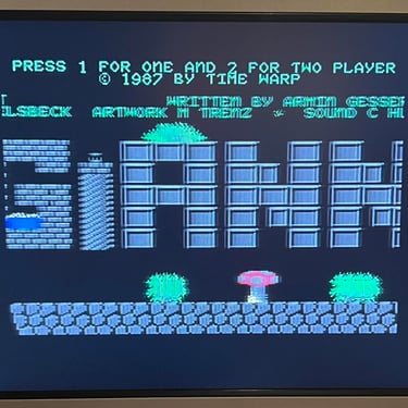
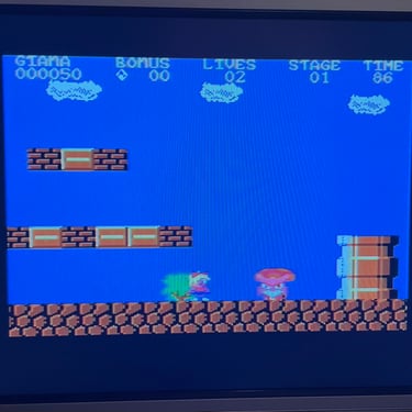
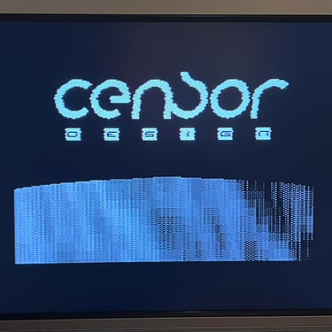
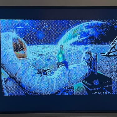
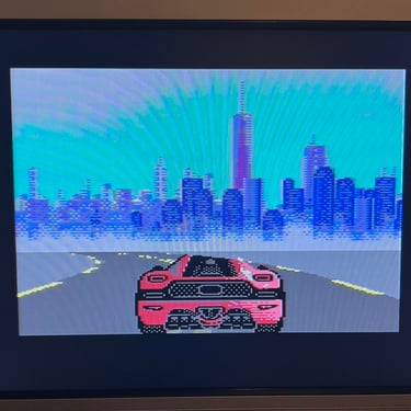
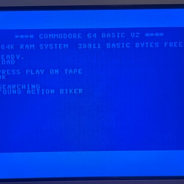
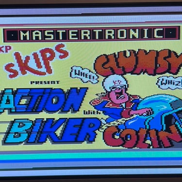
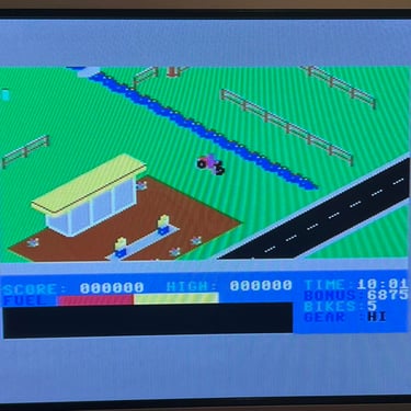
Knowing that the basic functionality of the machine works I continue the testing by using the Commodore 64 for normal operations; playing some games, watching demos, loading from datasette and floppy and using a cartridge. I can not find any issues with this machine. I also pay special attention to the video to make sure that there are no glitches in the graphics - I can´t see any abnormalities. Below is a gallery with pictures from the testing.
Final result
"A picture worth a thousand words"
Below is a collection of the final result from the refurbishment of this C64. Hope you like it! Click to enlarge!


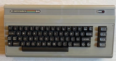
Banner picture credits: Evan-Amos