

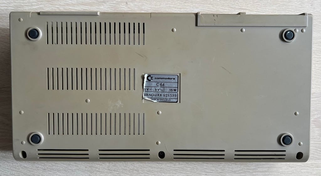
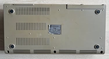
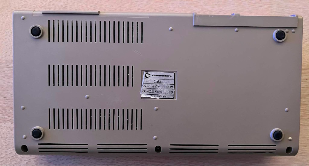
C64 Breadbin
Ser. No. 828599
Assy 250407
Artwork 251137 (REV B)
Starting point
This machine came in as "booting up", but unsure if really works. So I expect it to show the classic blue Commodore screen, but that there are some issues with it which I need to figure out and possible repair.
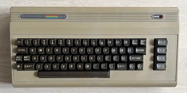
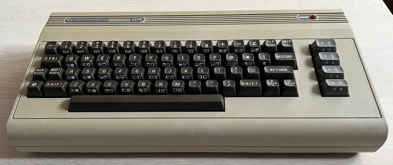
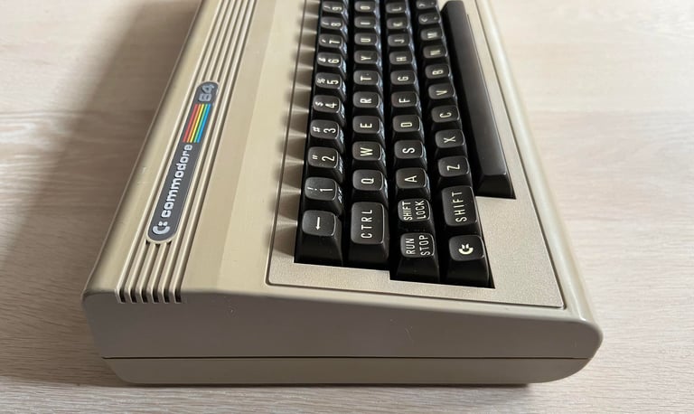
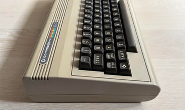
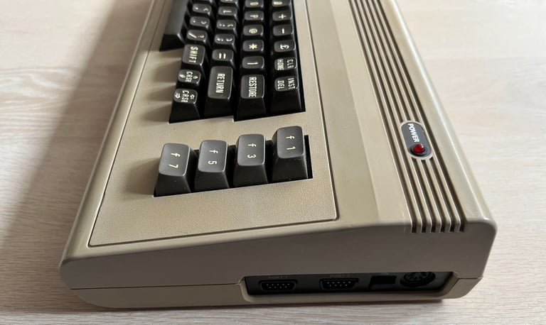
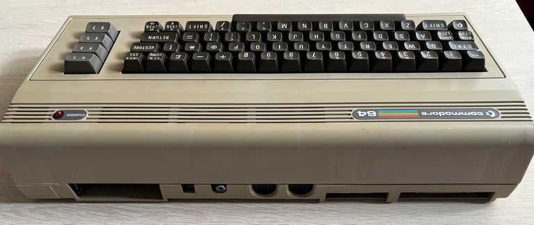
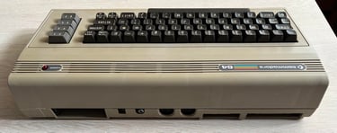
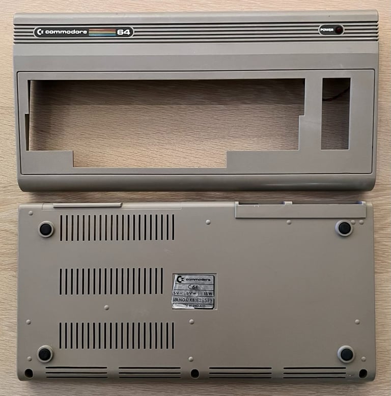
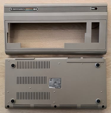
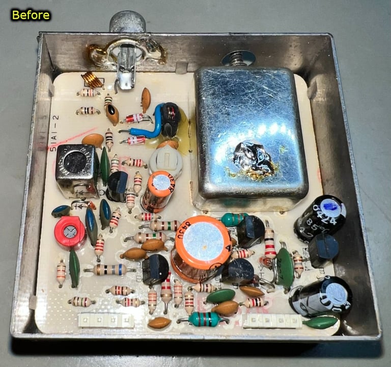
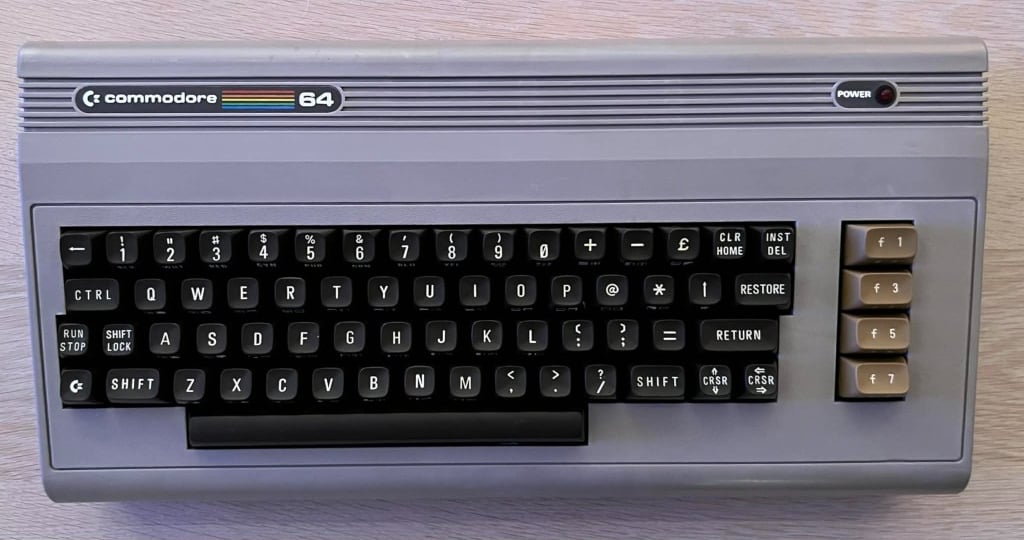
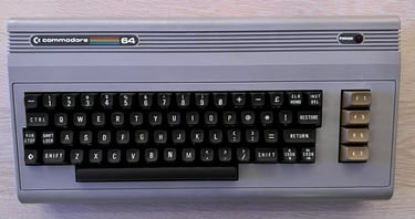
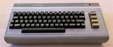
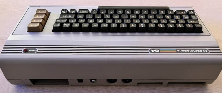
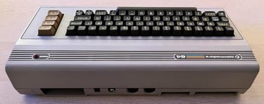
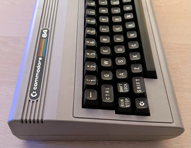
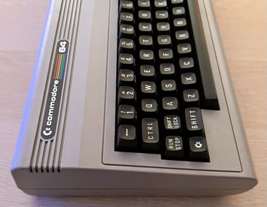
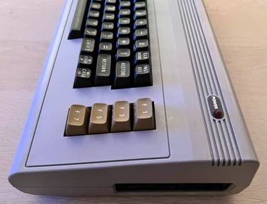
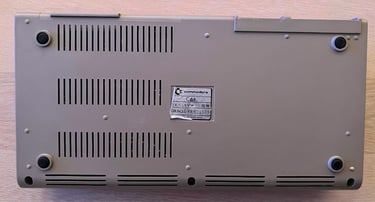
From the outside the casing and keyboard looks quite ok. There are some marks and dirt on the casing, but I don´t think it is very visible. I can´t see any visual damage on the machine or anything odd with it so I think this can be a nice (but perhaps challenging) refurbish.
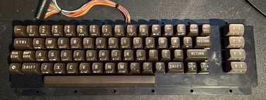
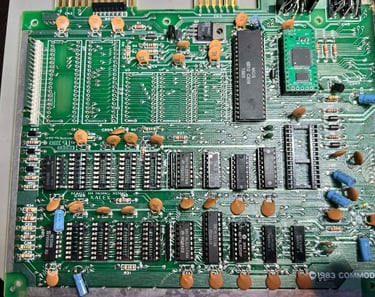
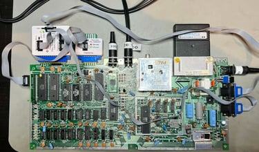
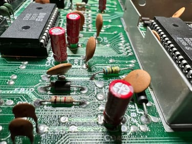
Below are some pictures of the Commodore 64 breadbin before refurbishment.


Refurbishment plan
The refurbishment plan for this C64 breadbin (some of them in parallell):
- Investigate possible fault(s)
- Clean and remove stains from the chassis
- Clean and restore the keyboard
- Refurbish main board (cleaning, checking, repairing, replacing capacitors and voltage regulators etc.)
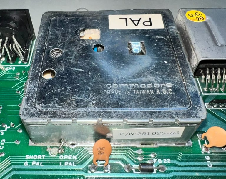
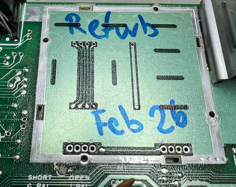
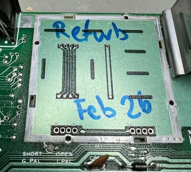
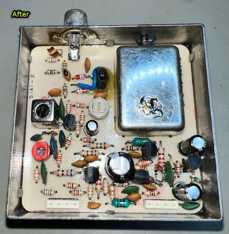
- Recap RF-modulator
- Verify operation by testing
The plan can be updated during the refurbishment process. Sometimes I discover areas that needs special attention.
Fault(s) investigation
As previously mentioned this machine is supposed to show the classic blue Commodore 64, but I do not expect it to work 100 % since there are some "issues" preventing it from working as it should. What these issues are I do not now yet.
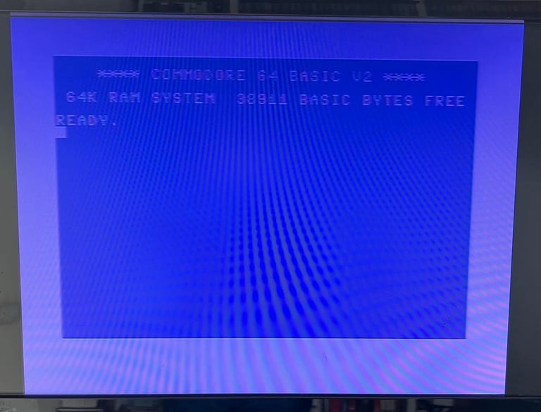
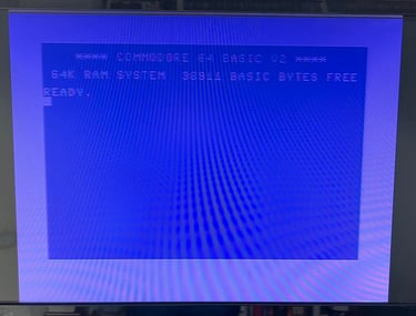
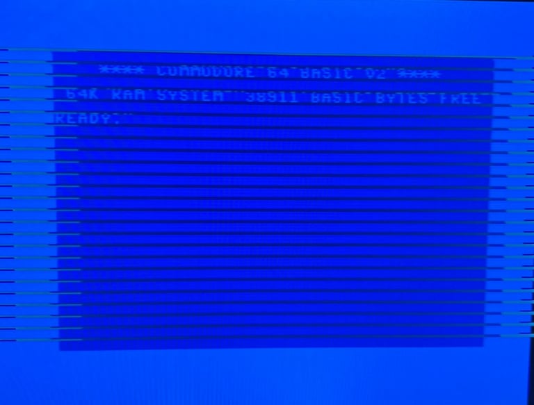
First power-on
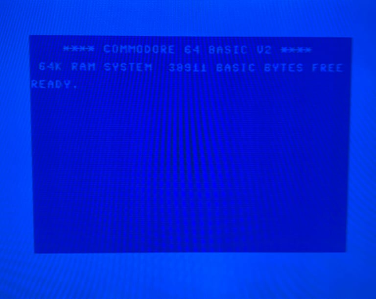
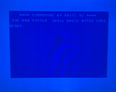
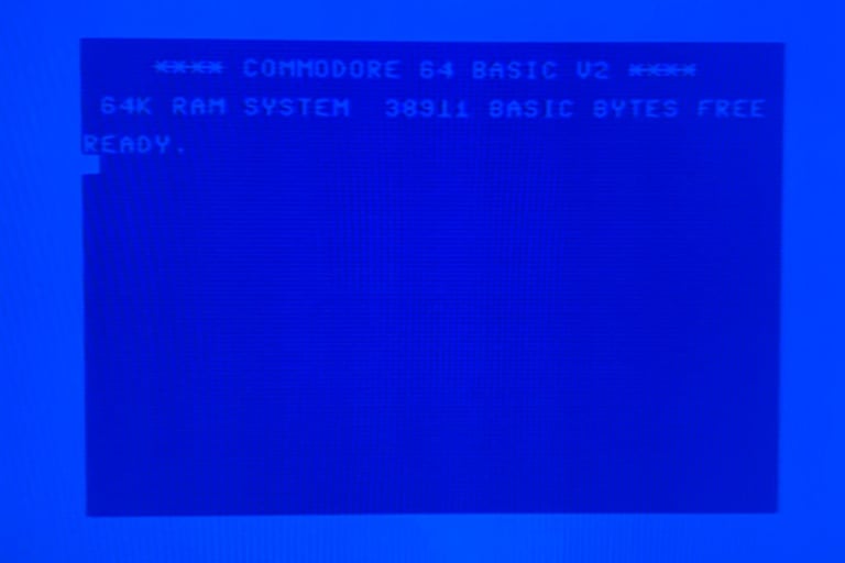
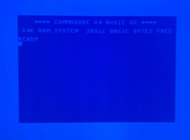
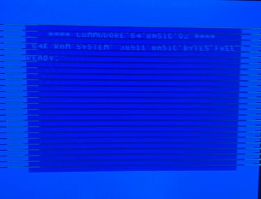
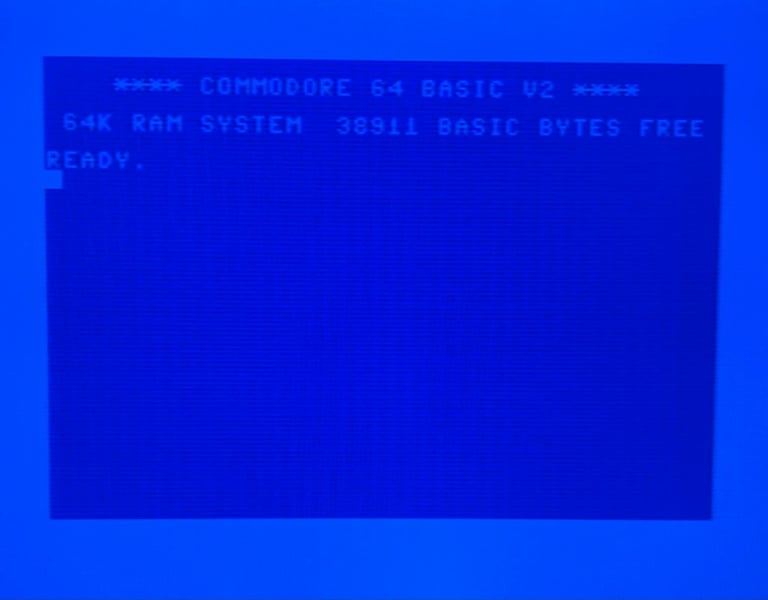
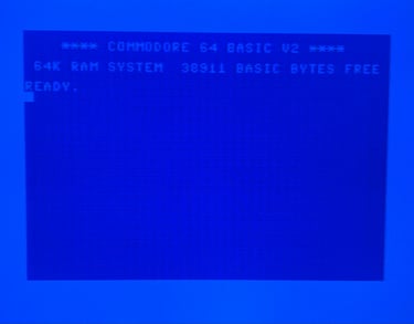
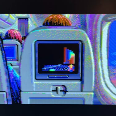
The machine start up without any issues. The classic Commodore BASIC blue screen. 38911 BASIC BYTES FREE.
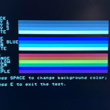
Dead test cartridge
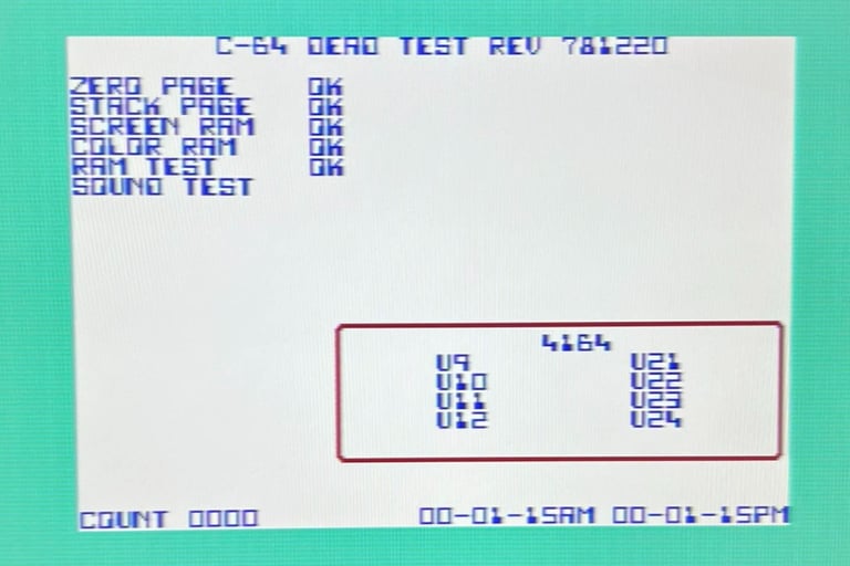
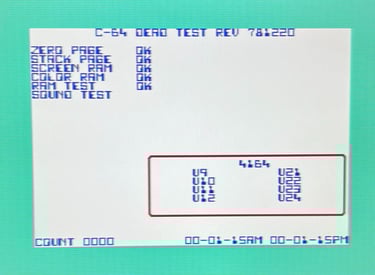
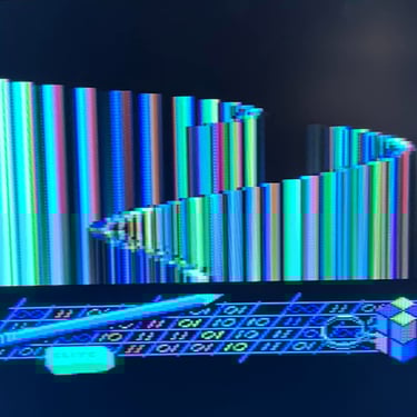
When using the dead test cartridge something interesting happens... There are some strange flashing, and only for a short moment the dead test screen is visible. I wonder if this could be related to either some memory bank switching or memory faults in one or several of the chips. In the video below you can see how the machine operates when the dead test cartridge is installed.

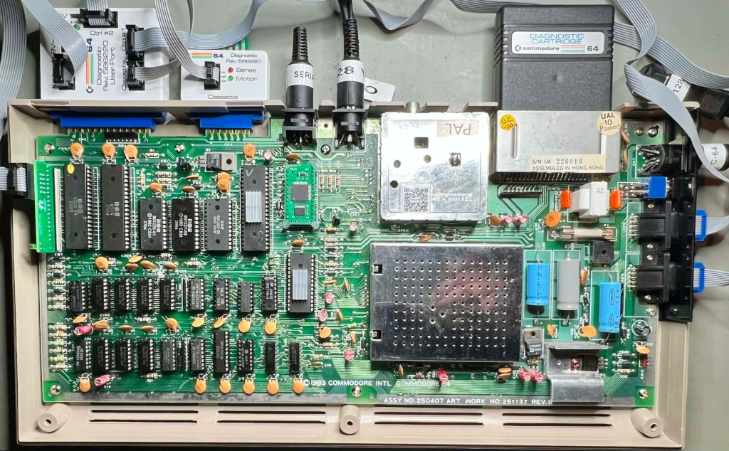
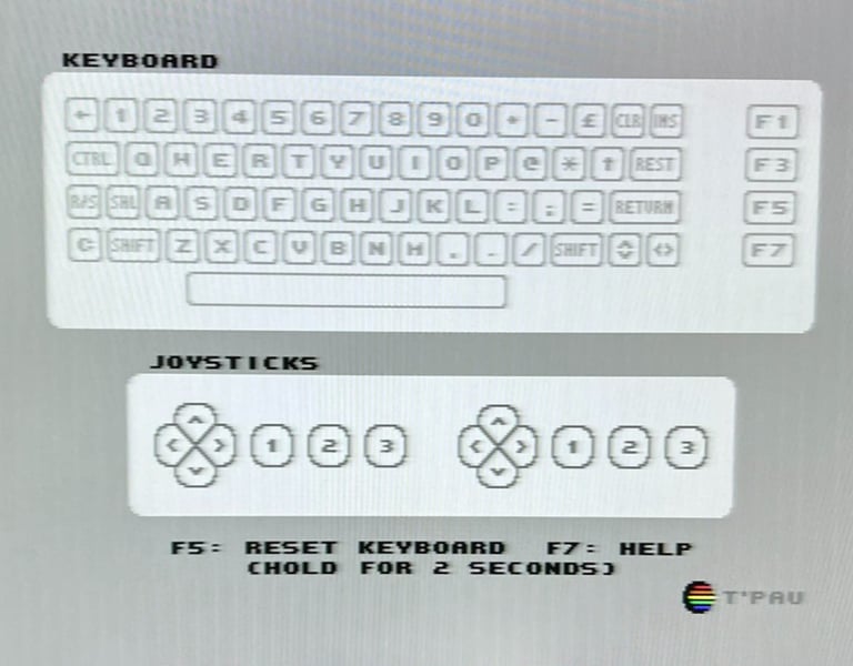
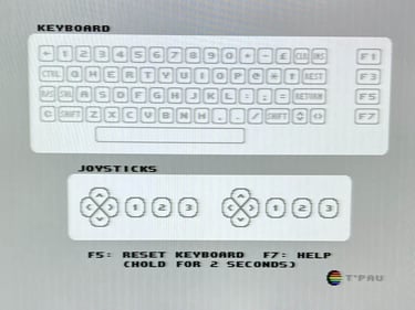
Diagnostic cartridge
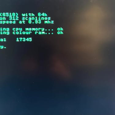
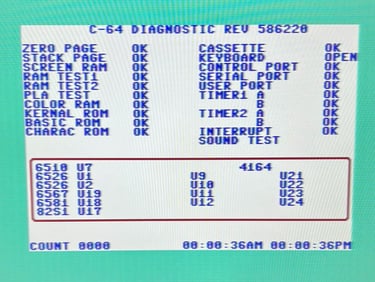
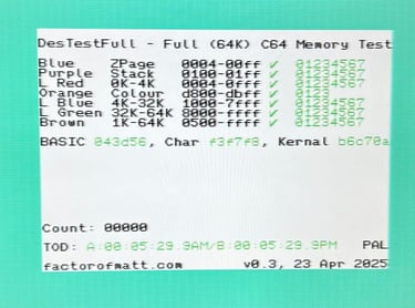
The diagnostic cartridge is an interesting tool (even without the harness). Unlike the Dead test cartridge which works in "Ultimax" mode, the diagnostic works in a "normal" 8K mode so it can show different results than the Dead test. And it does... it stops (or more precisely crashes) at the RAM Test #1. See video below,
Normal operation
Now things are starting to be really interesting. This Commodore 64 machine seems to works quite fine - except for some areas! Here´s what I have seen so far (will be updated as I work):
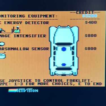
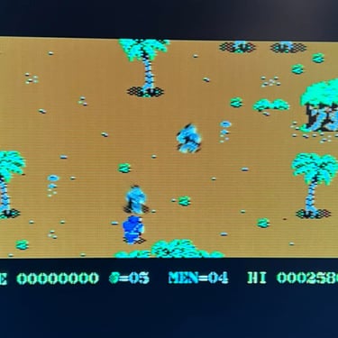
Normal game cartridges such as International Soccer works fine.
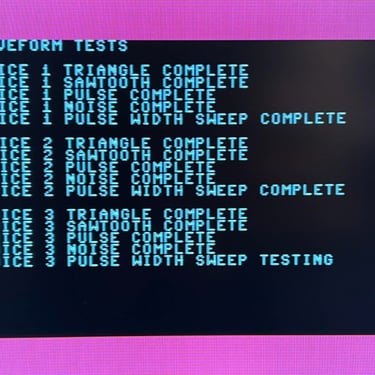
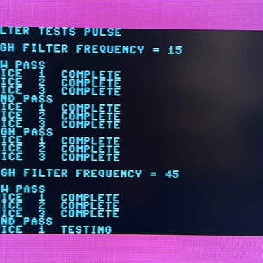
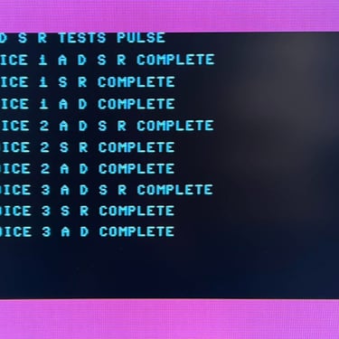
SID chip seems to be marginal (I hear some strange noises).
Using the Ultimate 1541 II+ cartridge to emulate disk drive I can load any game or demo just fine.
"All" demos and games I load works just fine. I have only found one demo which crashes in one part of the demo.
Either the power connector and/or the power switch have oxidized preventing the machine to start from time to time. Spraying some contact cleaner into these it starts up.
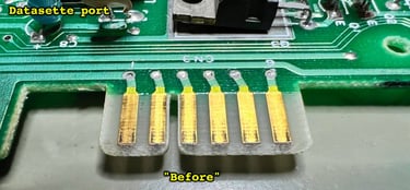
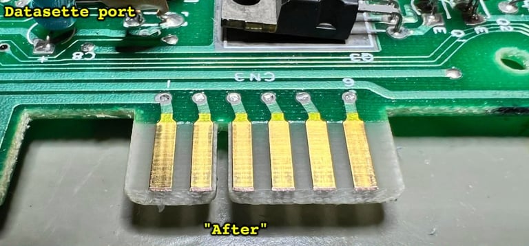
Identified after step #7: pressing SHIFT+RUN STOP make the Commodore 64 start loading immediately - even if there is no datasette connected! So this was strange...

Exterior casing
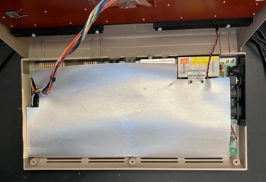
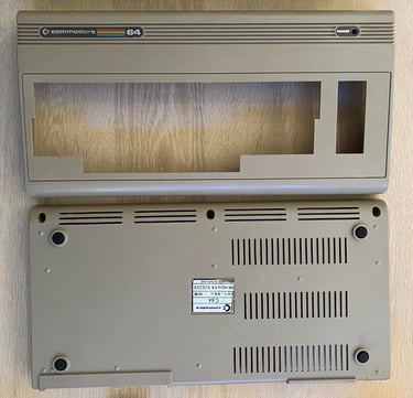
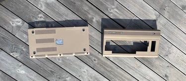
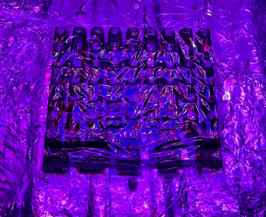
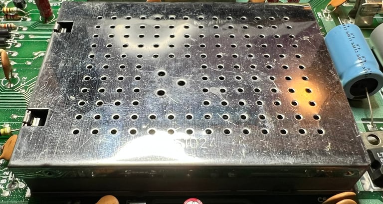
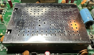
The exterior casing consists of a top- and bottom cover. These two cover are attached by three screws at the bottom and some "clips" at the backside of the top cover. When the screws are removed the top cover can be lifted. This reveals the mainboard covered in a cardboard RF-shield.

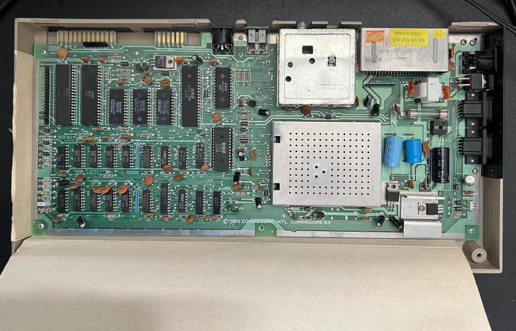
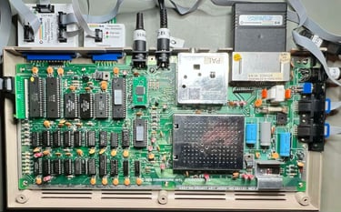
RF-shield is lifted and the mainboard PCB can be seen.

Both top- and bottom cover are cleaned thoroughly with mild soap water and glass cleaning spray. Also, some of the marks are removed with isopropanol.

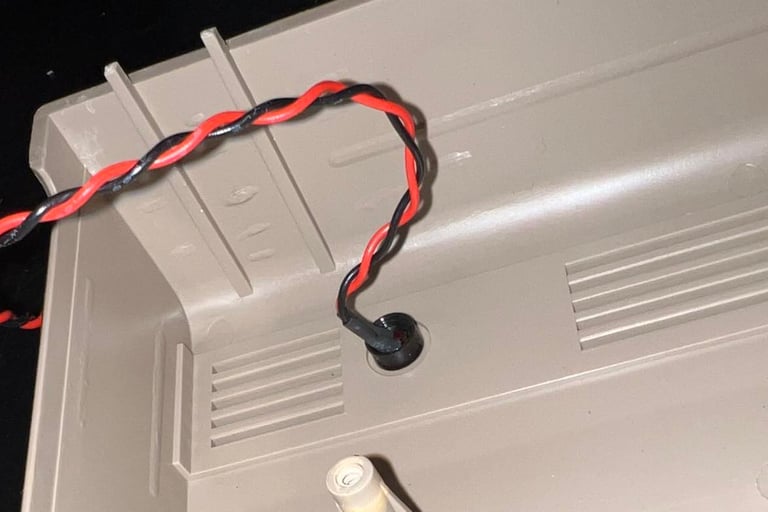
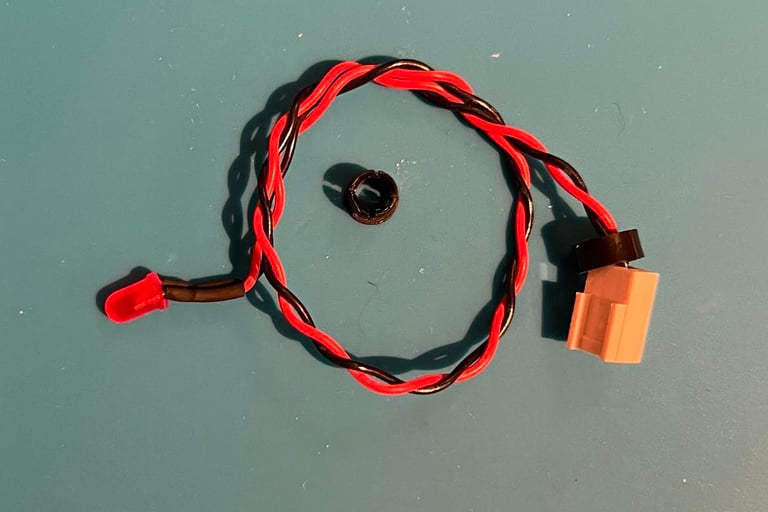
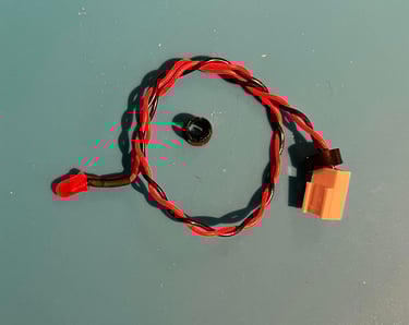
The LED is removed by first pulling away the small circular spring. Then the LED is pushed firmly from the front to the back. This will make the LED "pop out" of the plastic clip. Finally the LED clip holder is removed by firmly pushing it from the back to the front while at the same time pinching the holder.

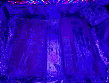
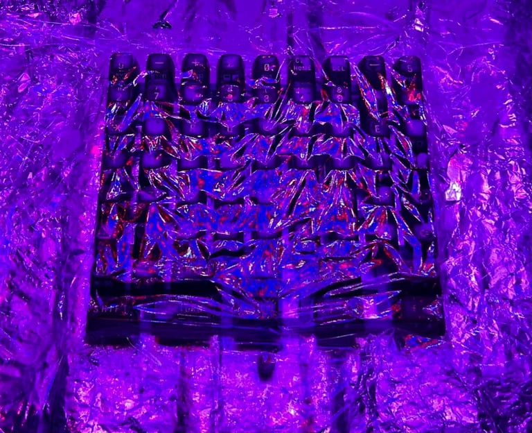
"Sun always shines on TV"! Yes, but is doesn´t always shine in Stavanger (Norway) where I live. Nevertheless, there are days where the sun is shining bright. And such days I try to use for some sunbrighting!


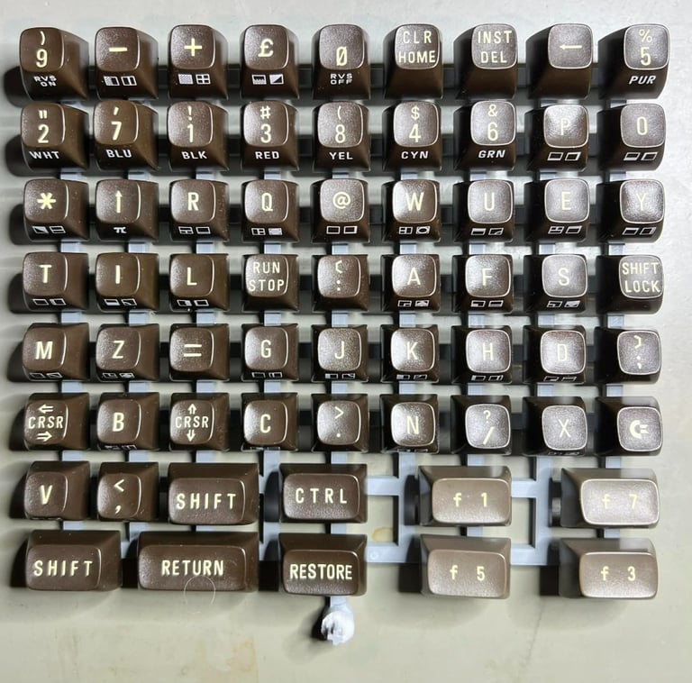
Keyboard
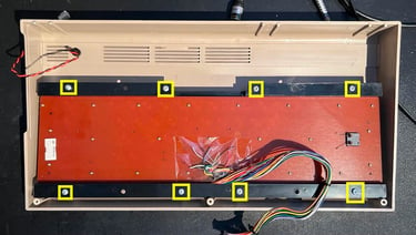
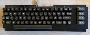
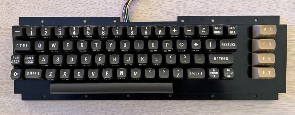
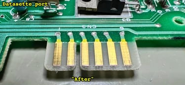
The keyboard is removed from the top cover by removing the eight screws - see picture below (yellow squares).

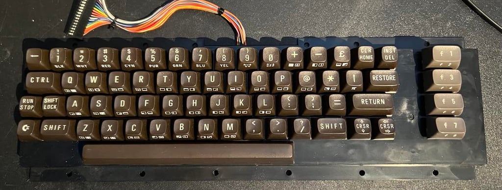
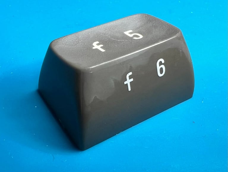
I am really surprised how clean this keyboard already is. I find it hard to believe that this has not been cleaned previously. Nevertheless, I will give it a proper clean again just to make sure that all the "goof" is gone. Also, I notice that all the printing on the keys seems to be intact. Nice!
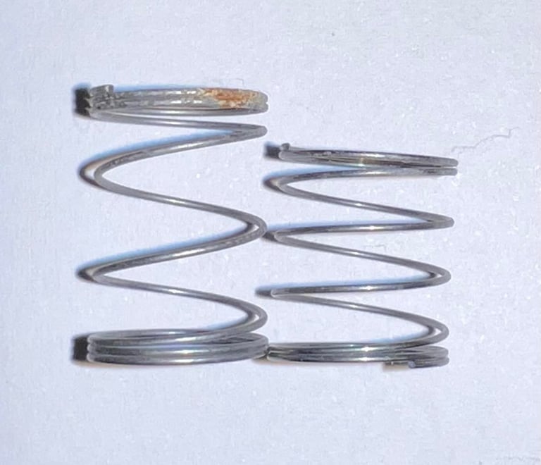
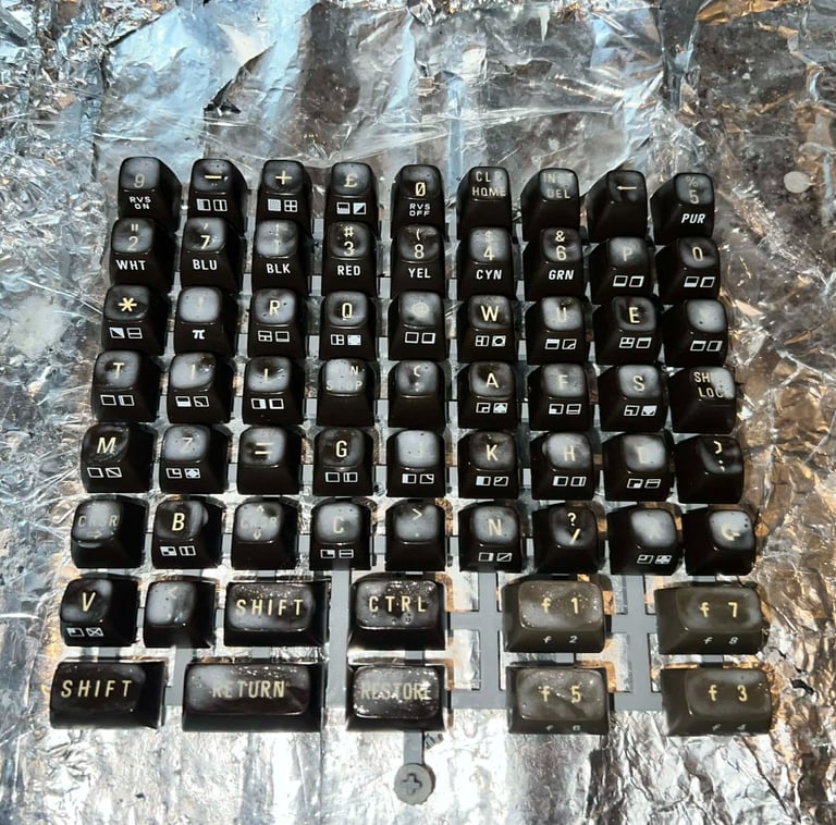
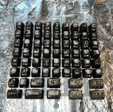
All keys are carefully removed with keycap puller and placed in mild soap water for 24 hours. Note that behind each key is a spring, and that the spring for the spacebar is a bit larger than the rest. So it is wise to place this spring in a separate bag when doing the refurbishment.

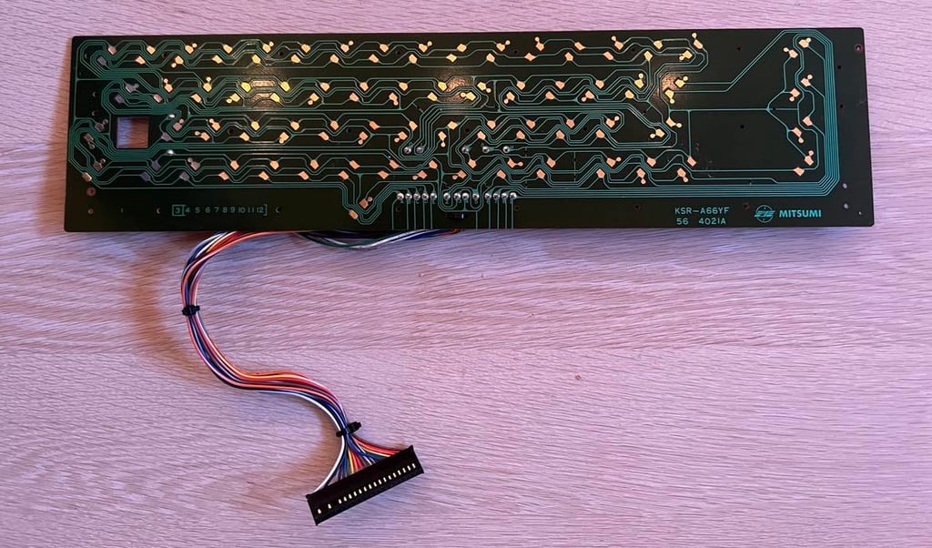
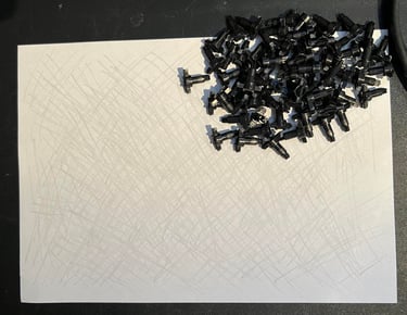
The SHIFT-LOCK key is removed by first desoldering the two wires at the backside of the keyboard. Then the SHIFT-LOCK is pushed firmly from the backside to the front - until it "pops" out. All the small screws are then removed and placed in a small plastic bag. This will then release the PCB itself from the plastic chassis.
Cleaning the PCB (which is a MITSUMI KSR-A66YF) is done by spraying isopropanol on it and then gently wiping it off with a paper towel.
All the key plungers are revived by gently wiping of the grease and debris from the rubber parts. I use this method instead of cleaning them with isopropanol. If this gently cleaning doesn´t work I will use alcohol, but I try with this more careful solution first.

Finally all parts are re-assembled after cleaning and drying. The keyboard look good as new.


Mainboard - Repair
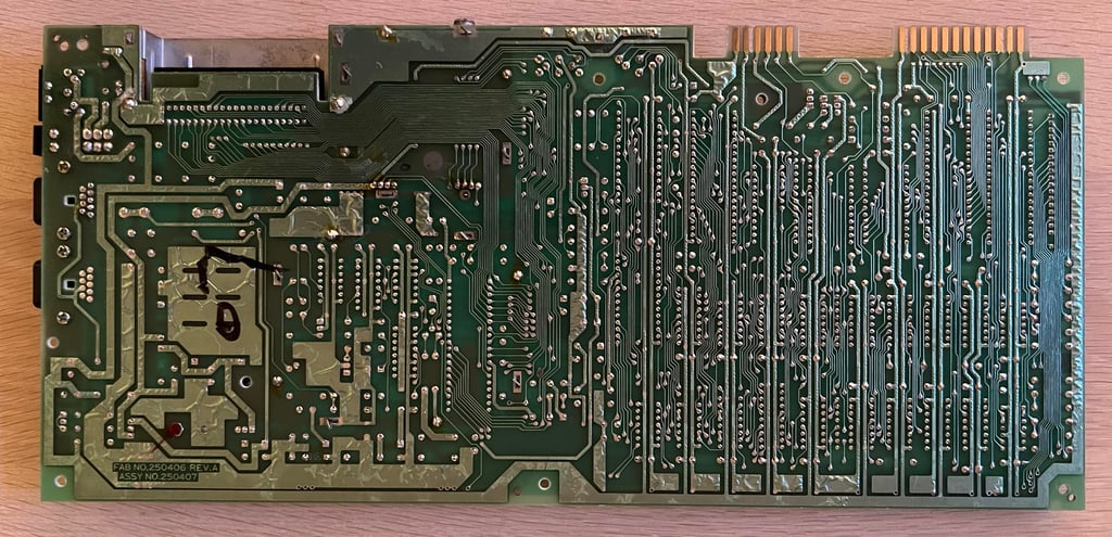
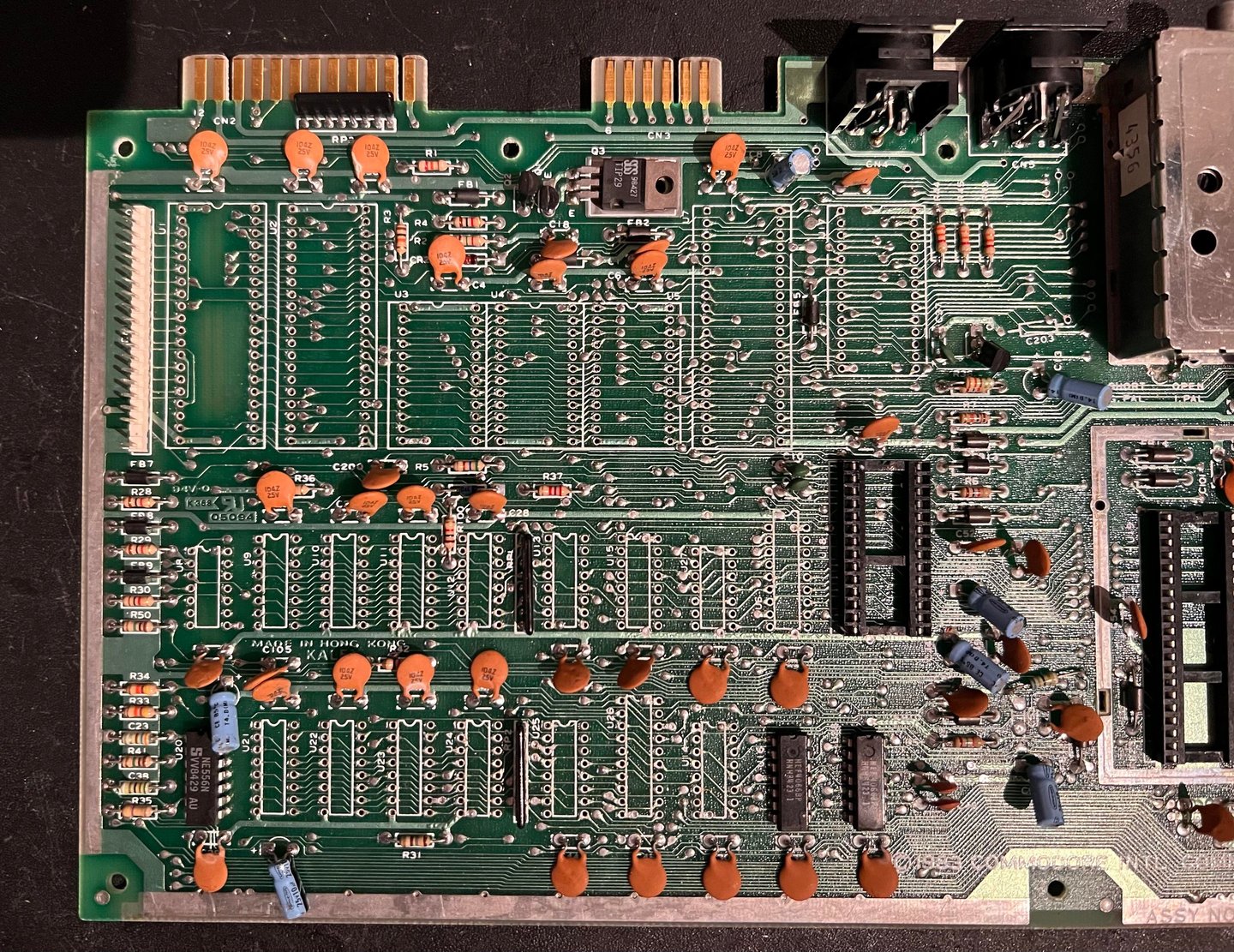
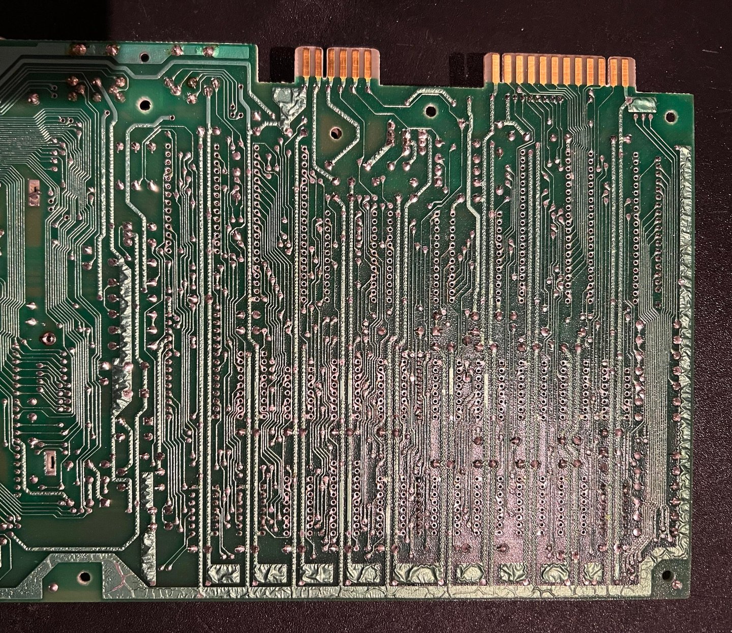
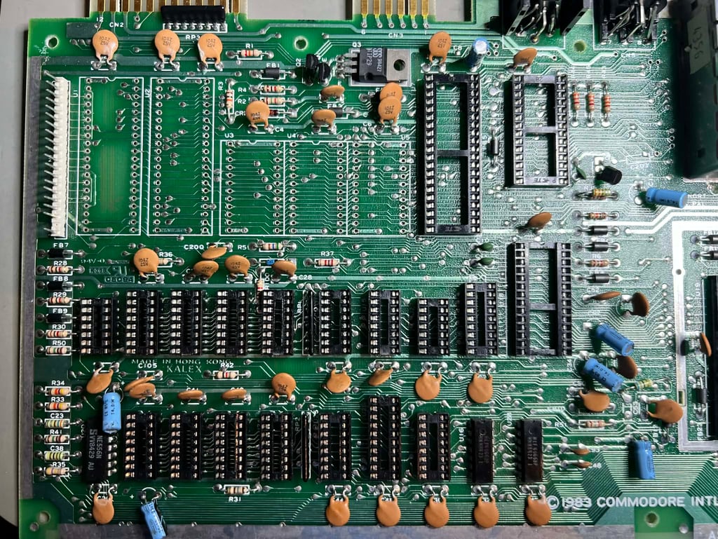
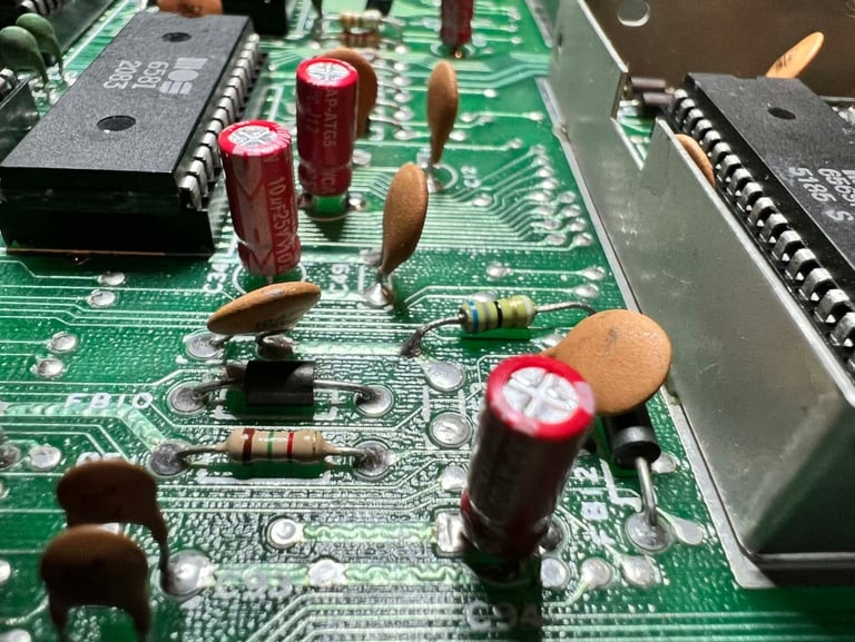
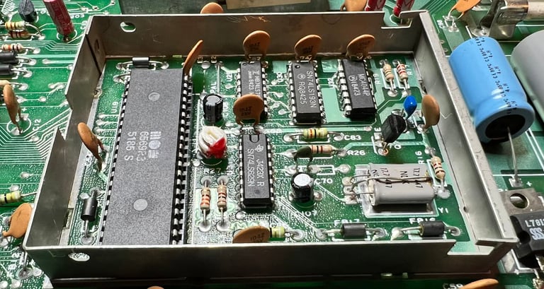
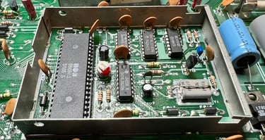
Before I start the repair the mainboard is washed with water and some mild dishwasher soap, and left for a couple of days to dry while spraying it with isopropanol from time to time to make the water evaporate. After cleaning the mainboard looks quite good - see pictures below.
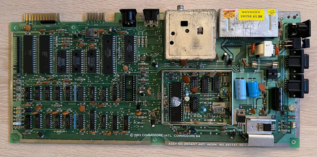
Visual inspection
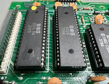
This mainboard version is assy 250407 artwork 251137 Rev B in the "longboard" family with the original SID, VIC and CPU. I can not see any visual damage on the board such as corrosion, broken parts or traces. They can still be there, but they are at least not obvious.
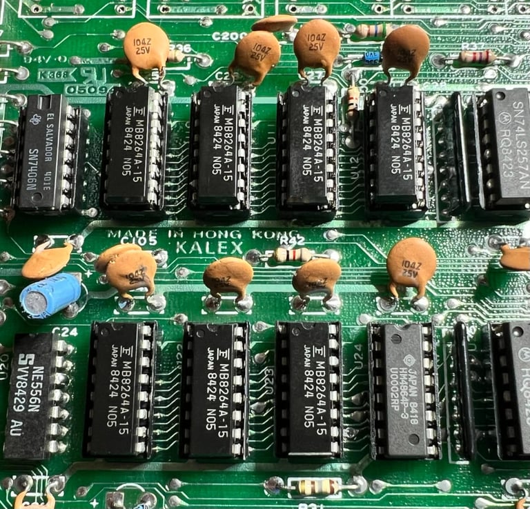
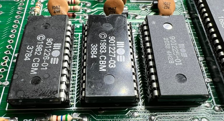
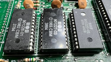
In the table below is an overview of the major chips installed on the mainboard before repair. As seen from the date codes in the table, this machine was probably manufactured some time mid 1984 (the VIC is dated week 27 of 1984).
Voltages
All voltages seems to be ok and within acceptable range. (Nevertheless, there are something wrong with the power connector or the power switch I believe. From time to time the machine is completely dead - either with no voltages whatsoever or only 9 V AC or 5 V DC. I probably need to check and clean these). The voltages before refurbishment are listed in the table below. Note that this table will be updated after repair and refurbishment is complete also. For a detailed description about checking the voltages I recommend my article Checking C64 voltages.
Repair strategy
This paragraph is likely to be updated as I try to repair the machine - if the strategies do not make the machine work.
The plan is as following:
Replace the PLA - these are notorious for failing. It could be that the PLA is marginal making the Dead Test and Diagnostic cartridge fail
Replace the MOS 7711 and MOS 7709. I will replace these anyway since MOS glue logic are prone to fail du to old age. There are good modern replacements for these (MOS 7711 <> 74LS139 and MOS 7709<>74LS258)
Replace the 7406. These also tend to fail due to old age and is an important part of the RAM management
Replace the Hitachi HM4864 RAM chip. Just a hunch. Since this is the only RAM chip by Hitachi (the rest is OKI).
Replace the 74LS08. This chip is to the DMA (CAEC) line from the cartridge port.
Clean the power switch
Oh... I am soon running out of ideas... But I need to be pushing forward!
Checking connectivity on all lines from the cartridge port
Check signals on CPU (6510) with oscilloscope
Remove all unnecessary chips (for starting the Dead Test); CIA #1, CIA #2, BASIC ROM, Kernal ROM and Character ROM
Repair execution
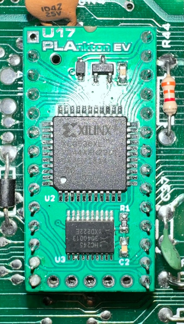
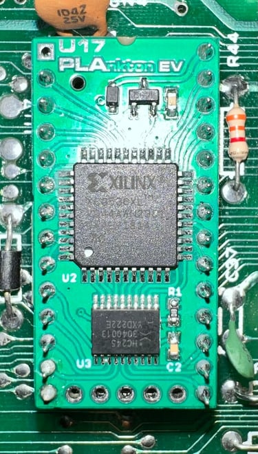
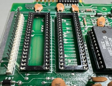
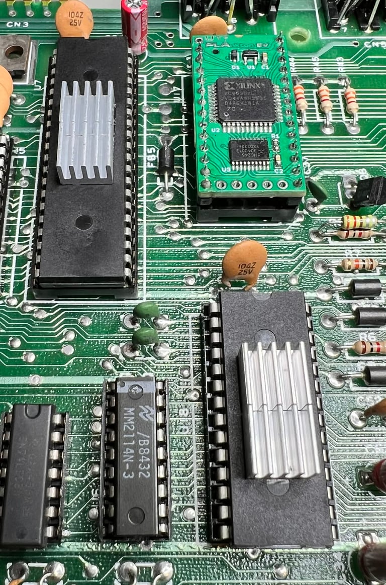
Step #1 - Replace the PLA (U17) - No improvement
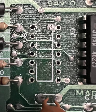
The PLA is desoldered and a new socket is installed. No traces or pads were damaged during desoldering. A known working PLA is used for testing, but the problem still persist. No improvement. Picture below shows the desoldered PLA.
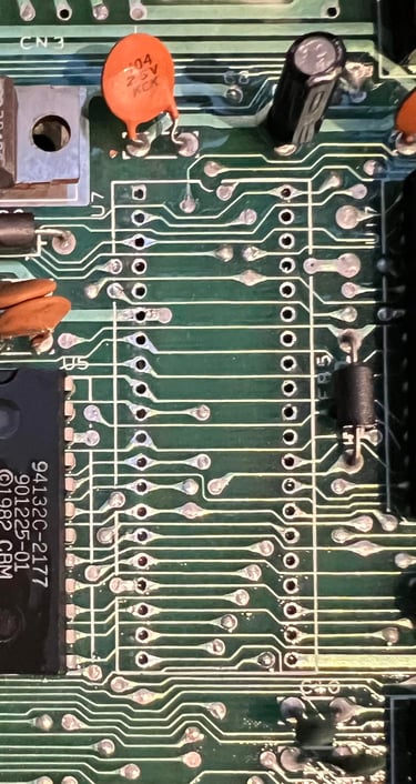
Step #2 - Replace MOS 7711 (U15) and MOS 7709 (U14) - No improvement
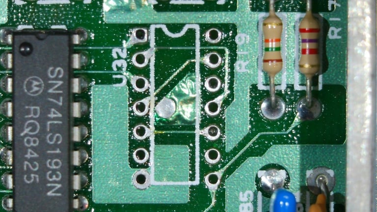
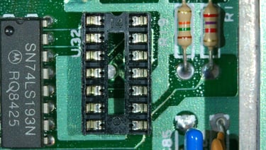
The MOS 7711 and MOS 7709 are part of the "glue logic" in the machine, but unfortunately the these chips fail quite often due to old age. The good thing is that there are good replacements available since this chips are nothing else than normal 74LS139 (MOS 7711) and 74LS258 (MOS 7709). So these chips would be replaced anyway - but the replacement does not help anything on the fault. It is still there. No pads or traces were lifted during desoldering (see pictures below).

Step #3 - Replace 7406 (U8) - No improvement
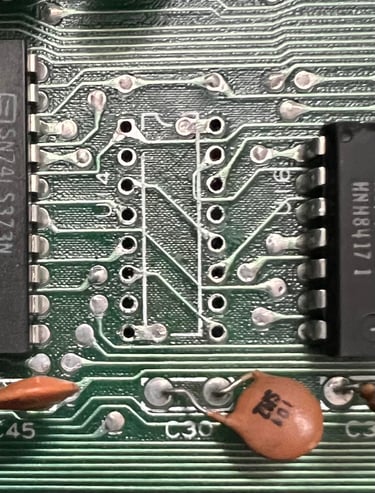
The 7406 is also part of the "glue logic" in the machine and is part of the memory management circuitry. This chip is also desoldered and a socket installed, but unfortunately this is not the fault either. No pads or traces were lifted during desoldering - see picture below.

Step #4 - Replace HM4864 RAM (U22) - No improvement
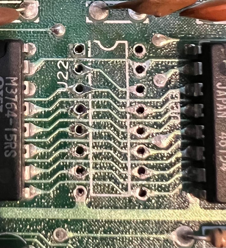
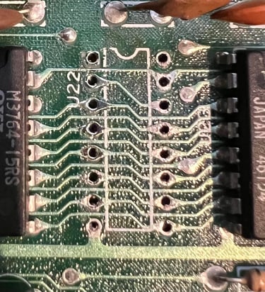
A shot in the dark here, but only one out of eight RAM chips are from Hitachi - the rest are OKI. So I decide to desolder and socket this RAM chip. Testing with a known good RAM chip does not show any improvement. No trace or pads lifted. See picture below.
Step #5 - Replace 74LS08 (U27) - No improvement
There is a DMA signal coming from the cartridge which goes through a 74LS08 chip. Could this be faulty? Well, it turns out that this was not the fault either. No trace or pads lifted. See picture below.
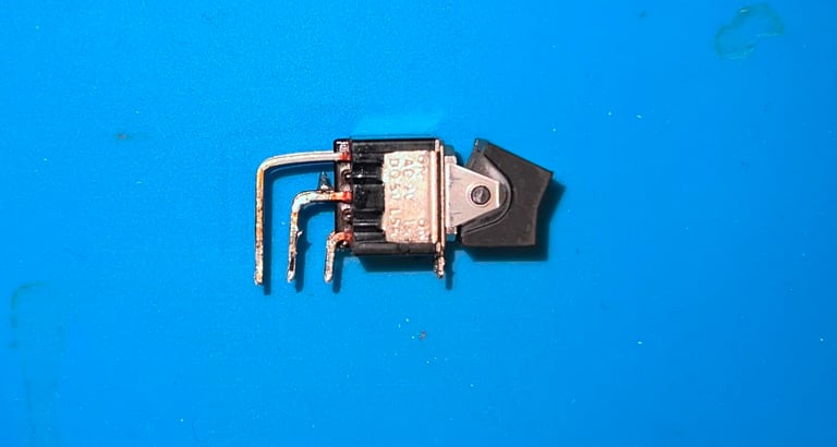
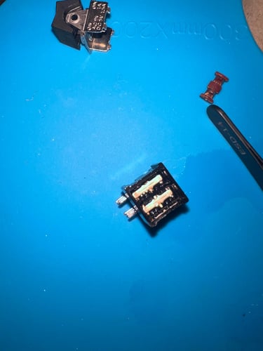
Step #6 - Clean the power switch - Improved on/off but main problem still persists
There is obviously something wrong with the power switch. When turning the machine on it often does not power on at all. Or that only the 9 V AC or the 5 V DC will get passed the switch. Could this also be causing the machine to malfunction? I doubt it, but I need to fix the switch anyway. The switch is desoldered, carefully opened and the metal parts inside are cleaned with isopropanol and electro spray. It is quite obviously that this switch was in need for some cleaning. After cleaning, the switch is put back together and soldered back to the mainboard. After this operation the mainboard is now turned on/off perfectly, but the "cartridge" problem is still there... Below are some pictures from the cleaning.

Step #7 - Check the expansion port connectivity - No improvement
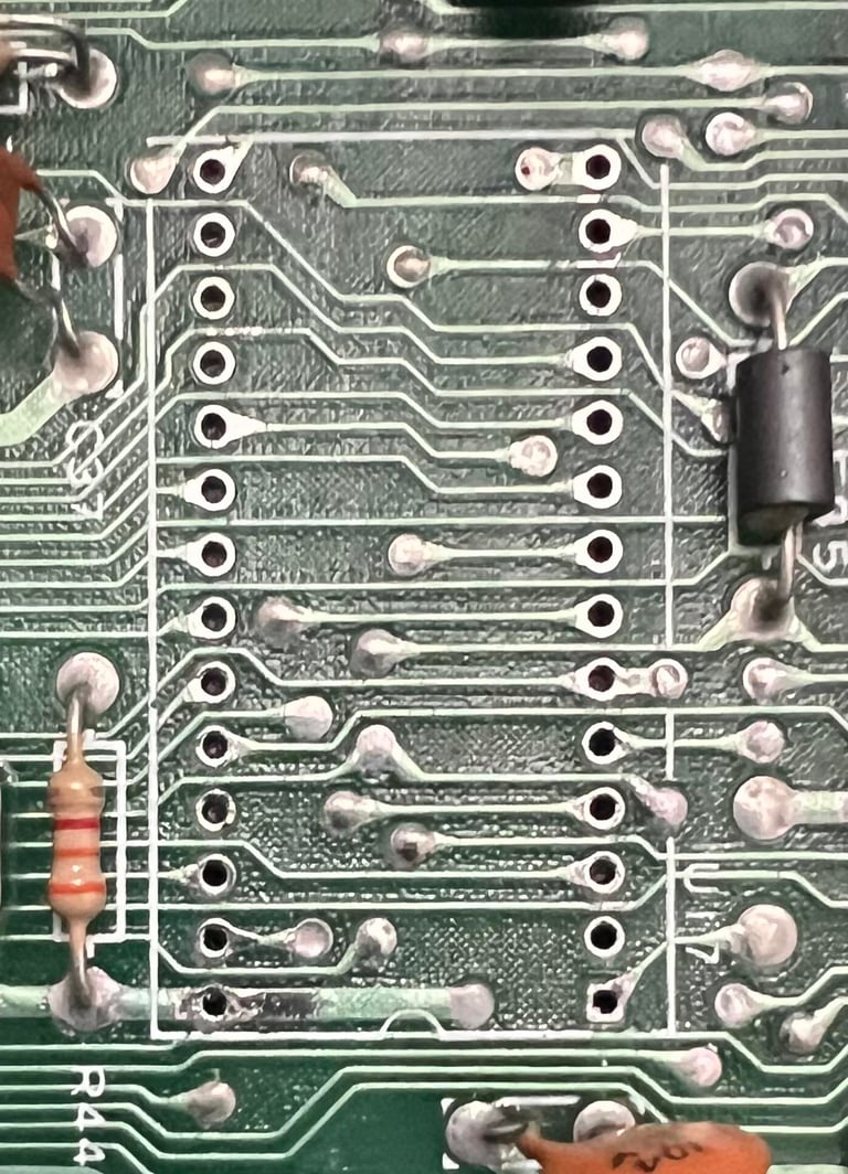
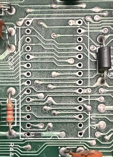
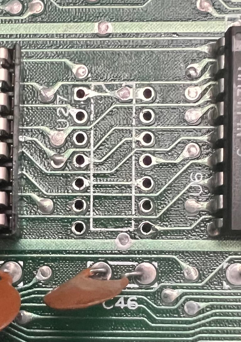
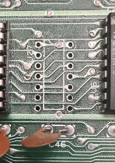
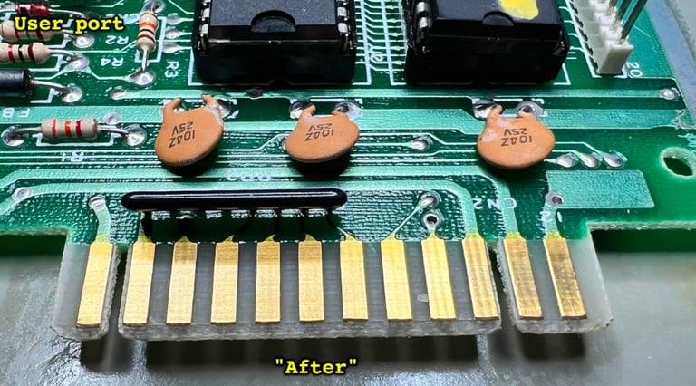
Could this fault be related to a broken trace? Or a faulty pull-up resistor? A short circuit? The cartridge port consists of 44 pins and I check connectivity, traces and voltages according to the Commodore 64 schematics. The picture below shows the pins (and their function) which I check.
All the connections seems to be fine as far as I can measure. Also, all pull-up resistors (connected to +5VDC) are measured ok so I really can not see anything wrong here either.
Step #8 - Check CPU signals with oscilloscope - A fault identified (but could be an additional fault) - SUCCESS!
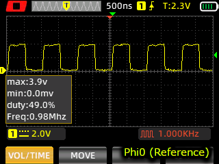
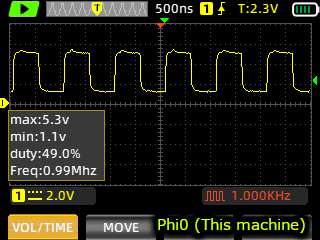
Using the oscilloscope to probe the signals on the CPU I discover some weird signal levels on pin 24, 25 and 26 on this chip. These signals should be either 0 V or 5 V, but these are something in between (?). See picture below from pin 25 on the CPU.
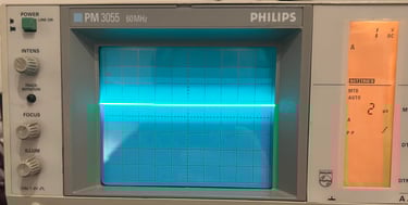
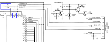
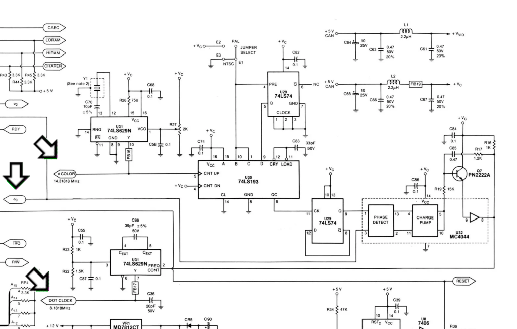
As seen from the scope picture above, the voltage level is only about 1.8 V. In idle mode the voltage level should be 5 V (via pull-up resistor R1) according to the schematics below and to the signal reference library for the MOS 6510 CPU. So either the R1 resistor is faulty (not likely) or there is some other short circuit or something wrong with the CPU.

The resistance between pin 25 and +5 V DC (user port) is measured to 1.8k Ohm so there is clearly something which is not right here. I desolder the R1 resistor and measure this to be 3.3k Ohm which is correct. So there is clearly something else wrong. I choose to desolder the whole MOS 6510 CPU (U7) - I wonder if it could be the CPU itself which is marginal. It is a bit tricky to desolder this chip, but I manage to get it out of the board without any damage to traces or pads as far as I can see. See picture below.

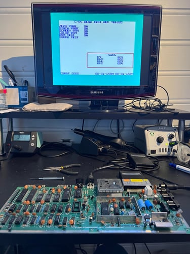
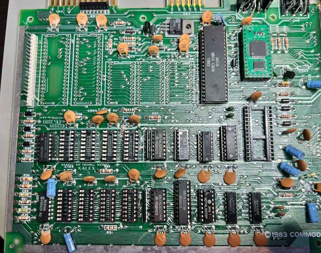
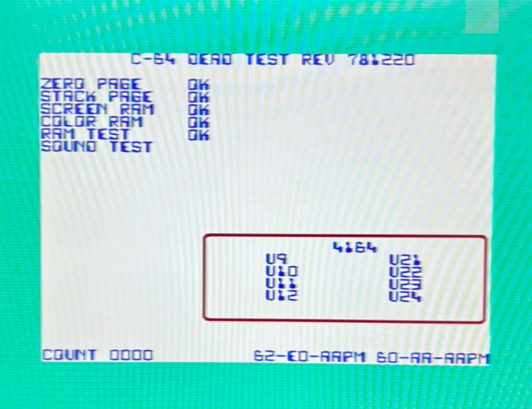
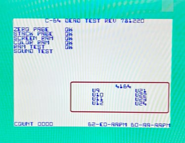
With a known working CPU the machine is tested again and ... SUCCESS! The MOS 6510 CPU (U7) must be marginal - it works 99 %, but the pin 24-26 which relates to the cassette sensor and motor are not working. My guess is that the datasette port has been exposed to static electricity and ruined the CPU input. The picture below shows the dead test cartridge screen working perfectly!

Phew... good to find the fault, but this is going to be an expensive repair! A marginal SID- and CPU chip! Oh my!
Changing the mainboard
I choose to change the mainboard in this machine with an identical (but faulty) mainboard. The reason for that is that it is better to get the other Commodore 64 machine to work at the moment, and then spend time after to repair the mainboard now used in this machine. I think that finding the fault on this mainboard can take several weeks (since I am only working on this as a hobby).
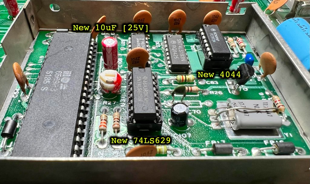
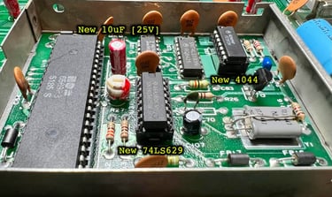
The chips installed in the new mainboard are listed below.
And the measured voltages from the new mainboard are listed in the table below. Note that this table will be updated after repair/refurbishment.
2nd mainboard - Repair
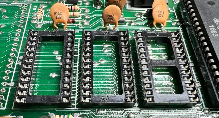
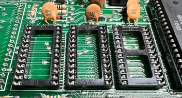
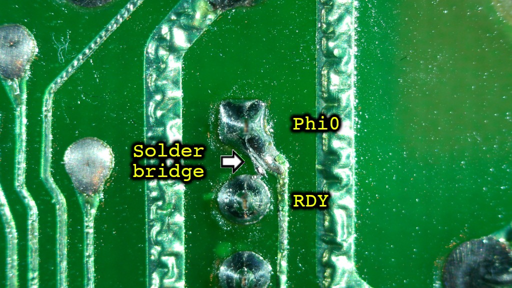
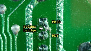
Since the mainboard was switched with an identical, but faulty, mainboard this needs to be repaired and refurbished. It´s been a while since I worked with this mainboard, but there were some odd faults which might be due to a bad soldering or bad trace. Therefore I decide to desolder most of the sockets to make sure that the PCB is good and that no traces or pads are broken. Below is a picture of the mainboard with everything desoldered. This might seem radical, but I want to make sure that there are no damage to the mainboard.


Banner picture credits: Evan-Amos