

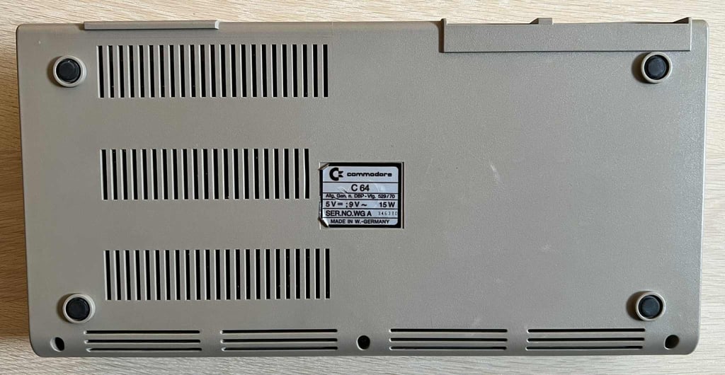
C64 Breadbin [PAL]
Ser. No. 346370
Assy 250425
P/N 251470-01 (REV A)
Starting point
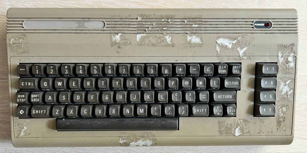
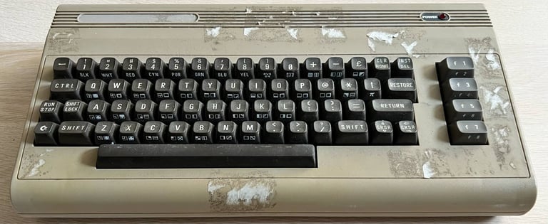
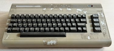
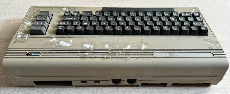
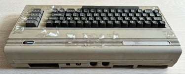
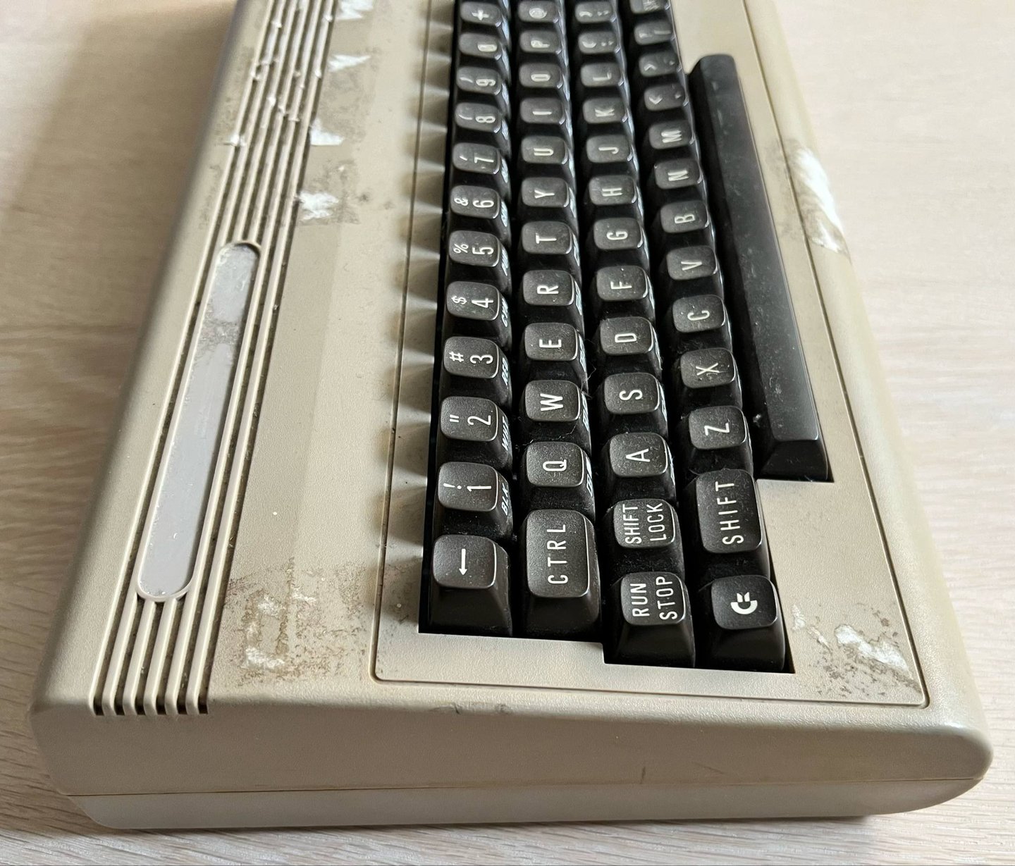
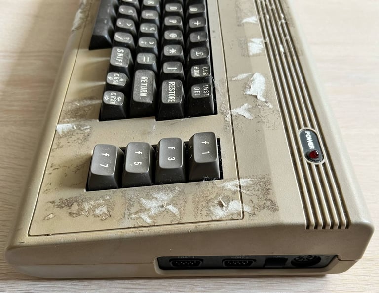
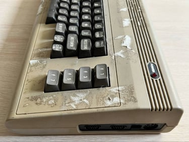
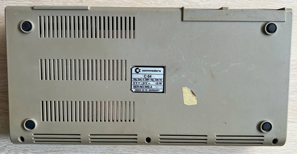
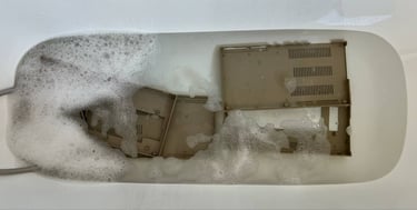
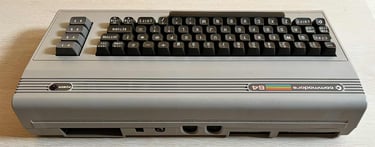
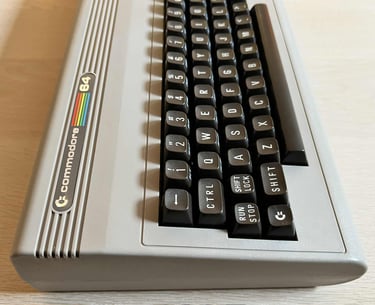
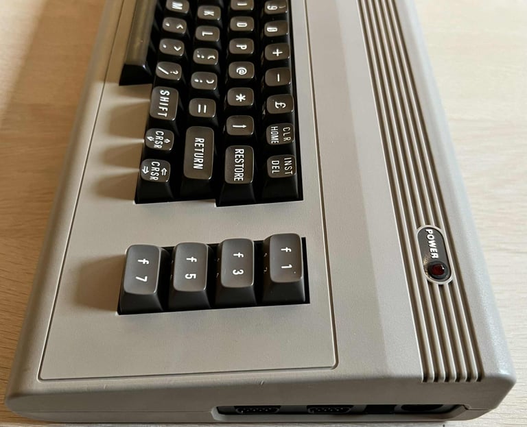
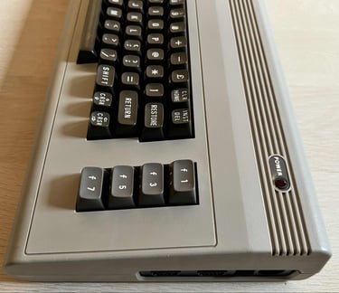
This machine, reportedly from 1986, has seen better days. The "Commodore 64" badge is missing, quite dirty and residue from stickers (oh, those 80´s). But, aside from that, the machine seems to actually be in good overall mechanical condition. The keyboard feels ok, all three screws are in place at the bottom and I can not see any significant outer damage. Whether or not this machine works at all I do not know yet.
A nice thing to notice also, is that the top cover has the embossed text showing what the different ports are. This is something many of the Commodore 64 breadbins are lacking.
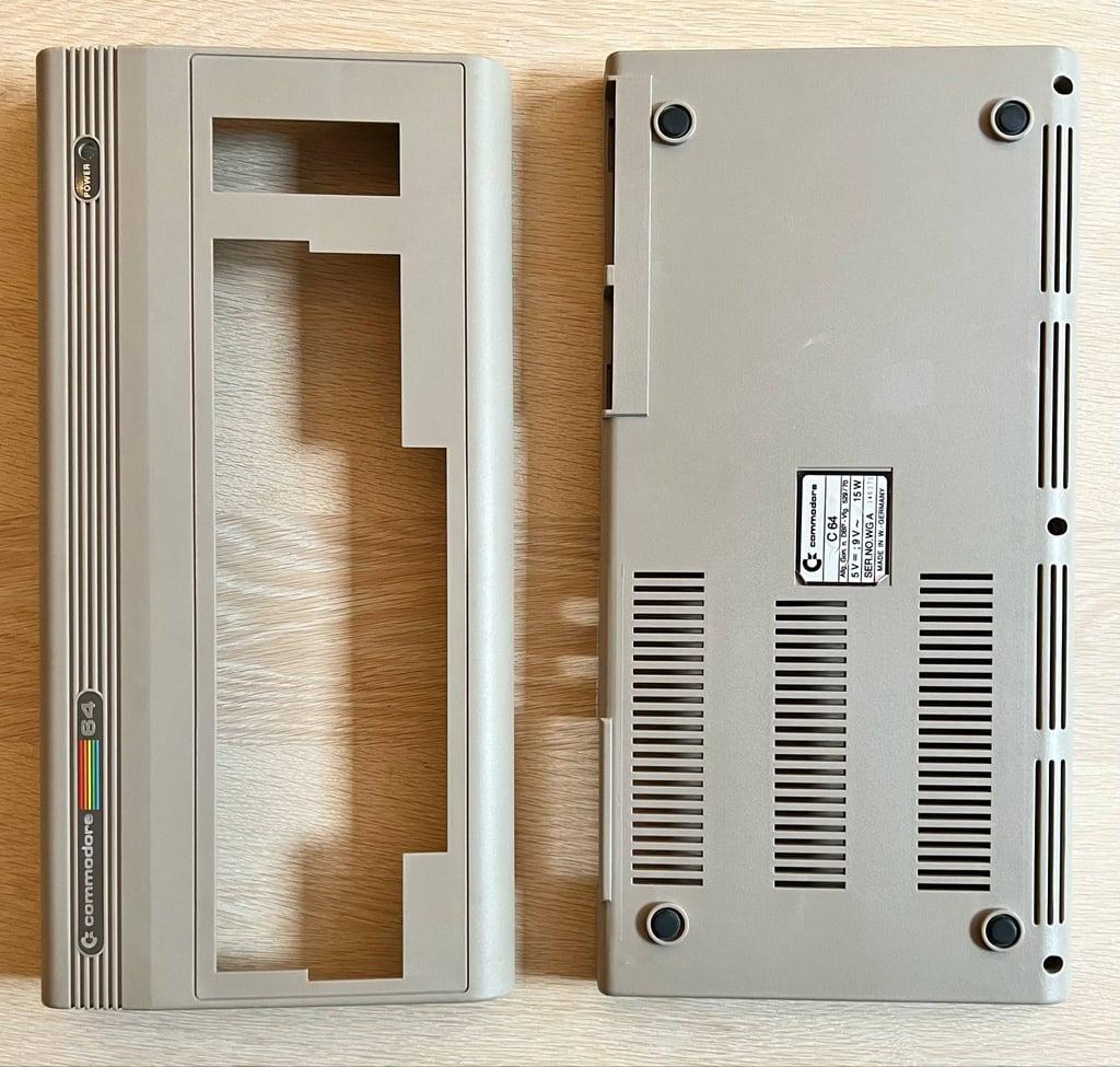
Below are some pictures of the Commdore 64 breadbin before refurbish.


Refurbishment plan
The refurbishment plan for this C64 breadbin (several of them in parallell):
- Refurbish the casing (cleaning, repairing and retrobrighting)
- Refurbish the keyboard (cleaning, reviving the plungers and retrobrighting)
- Refurbish main board (cleaning, checking, repairing, replacing capacitors and voltage regulators if required, adding heat sinks etc.)
- Verify operation by testing
The plan can be updated during the refurbishment process. Sometimes I discover areas that needs special attention.
Disassembly
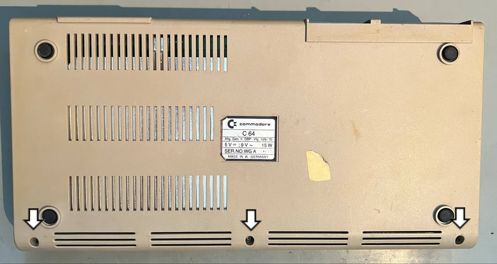
First step of disassembling the machine is to remove the three 3 x 6 mm Phillips screws at the bottom.

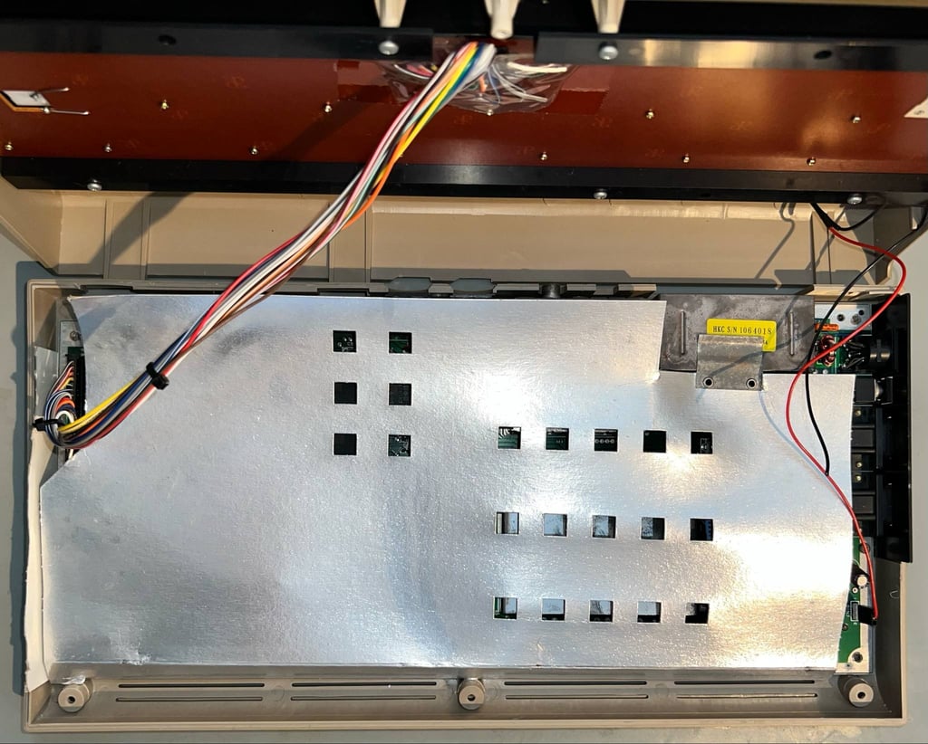
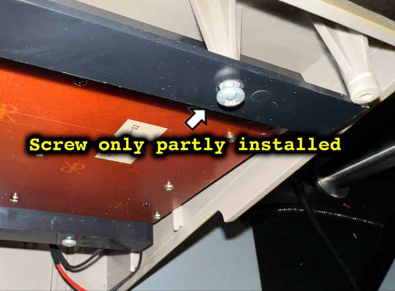
With the screws out of the way the top cover is carefully lifted from the bottom cover. By lifting the cover about 30 degrees, and the gently wiggle it loose, the top cover is freed. Now the interior is shown, and it looks to be in very good condition. Hardly any dust! Even the cardboard RF-shield looks like new. But I notice that one of the screws holding the keyboard in place is not completely in place. Something that happened during production? Or have the machine been serviced previously? Also, notice that one of the wires from the LED is broken off.


Removing the keyboard and LED
The keyboard is mounted to the top cover with eight 3 x 8 mm Phillips screws which are removed.
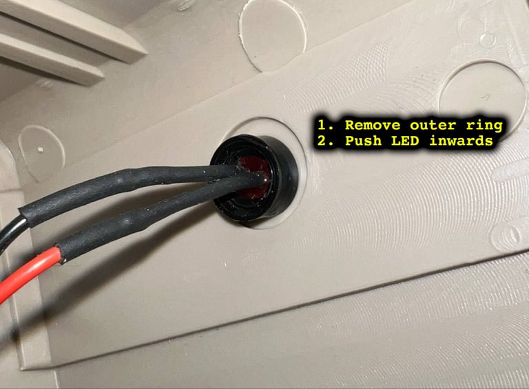
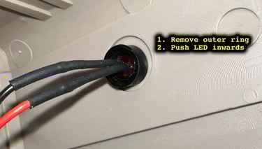
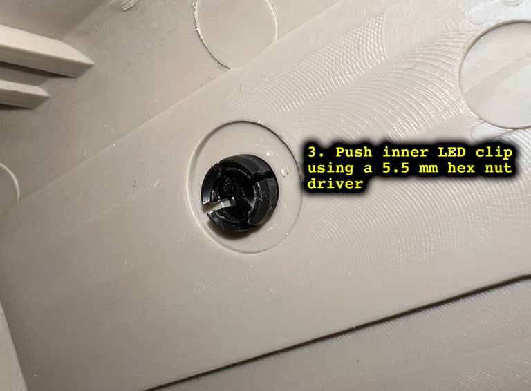
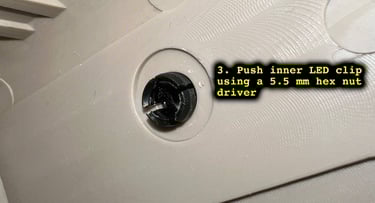
Removing the LED is not complicated, but can be very easy if you follow these steps:
Remove the outer ring surroundind the LED wires with a flat thin screwdriver. This will loose easily by prying it off.
Place the top cover firmly on the table top resting only on the tip of the LED. With a firm press on the top cover (now with the LED pressing on the table top) the LED will pop out
With a 5.5 mm hex nut driver the inner LED clip is pushed out (from the inside of the top cover towards the outside)
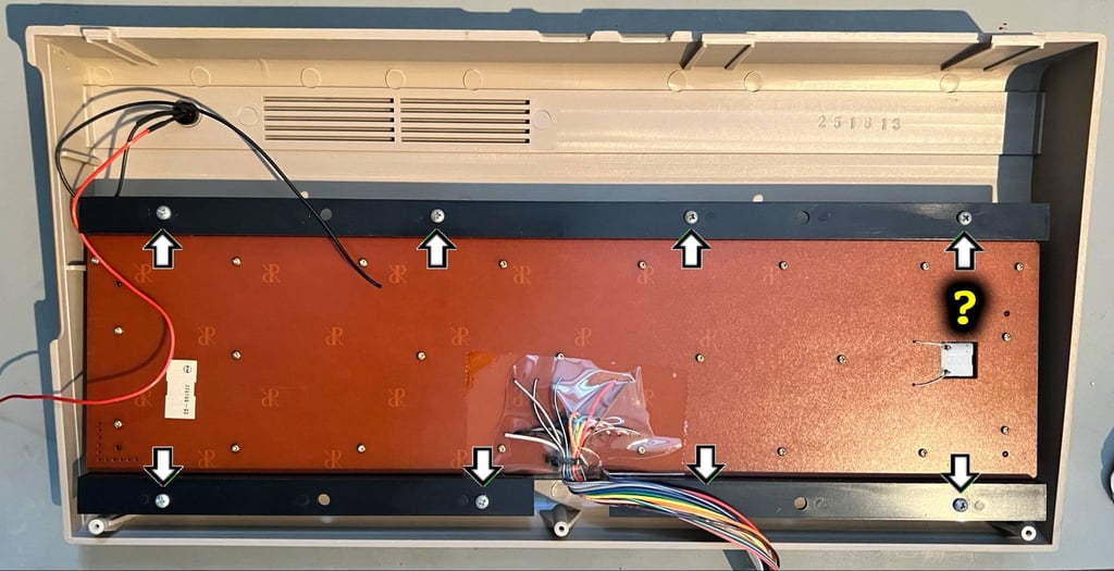
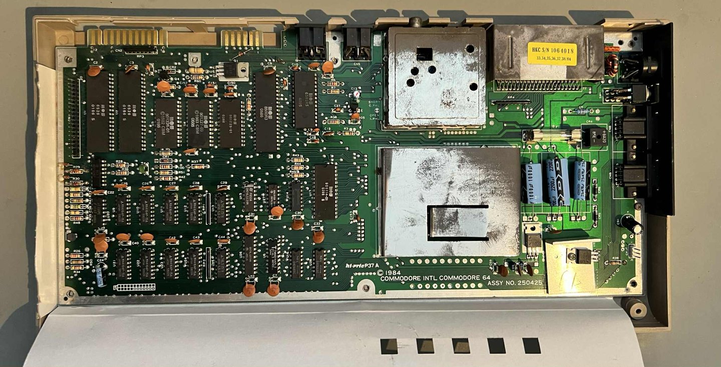
The cardboard RF-shield is lifted away and the PCBA is shown in all its glory. There is very little dust and grease inside, but one thing I notice... all the PCB screws are missing. So disassembly is "already done" - it is just a matter of lifting the PCB out of the bottom cover.

Casing
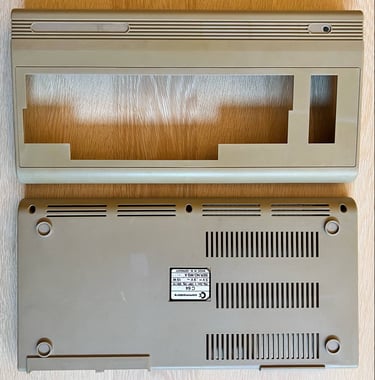
As seen in the introduction the casing is very dirty. There is a lot of residue from stickers, dust and grease. And the badge is missing. But on the bright side, the casing appear to be in mechanically good condtion with no damage.
First, the casing is placed in mild soap water for about a week (here together with another C64).

After the long bath there are still some sticker residue. This is removed with some isopropanol. After cleaning the covers looks way better!

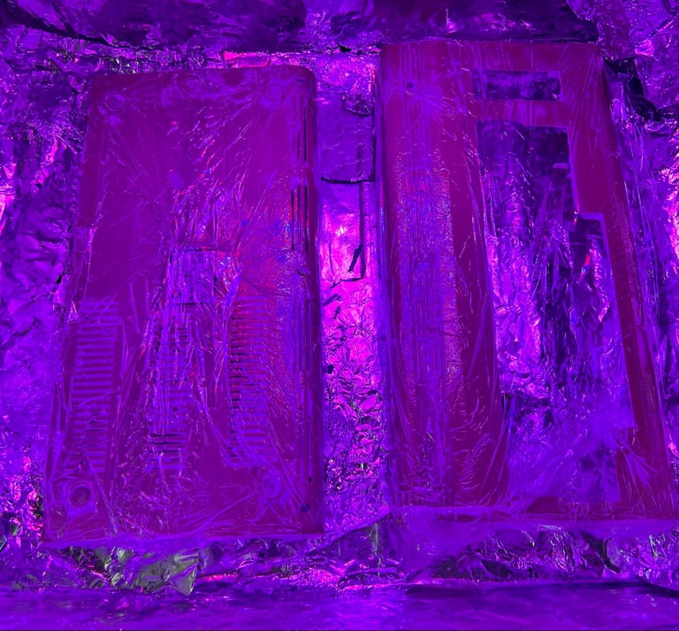
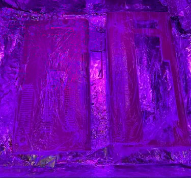
The covers are retrobrighted for about 12 hours straight. Retrobrighting is done using 12 % hydrogen peroxide cream, and exposing the covers for UV light. The cream is re-applied frequently to avoid the cream from drying out (and the covers are wrapped in plastic cling film).
After retrobrigthing the covers looks very nice! Notice that "new" badges are put on the covers. These are taken from this Commodore 64 NTSC machine.

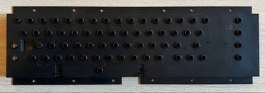
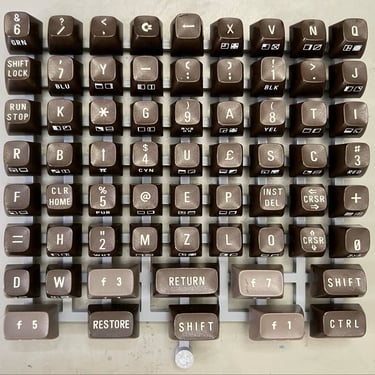
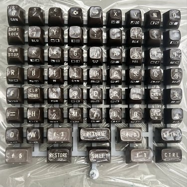
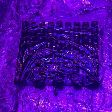
Keyboard
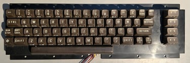
The keyboard is quite dirty, but it does appear to be in good condition otherwise. All keycaps are present, and from a mechanical point of view I can´t notice anything suspicious. Below is a picture of the keyboard before refurbish.

First, the keycaps are removed with a keycap puller. NOTE: for a complete guide on how to refurbish a Commodore 64 keyboard please see the HOWTO article. Using a keycap puller you reduce the risk of damaging the plungers - and the keycaps (also your fingers if you try to removed them by hand).
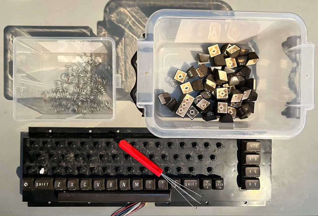
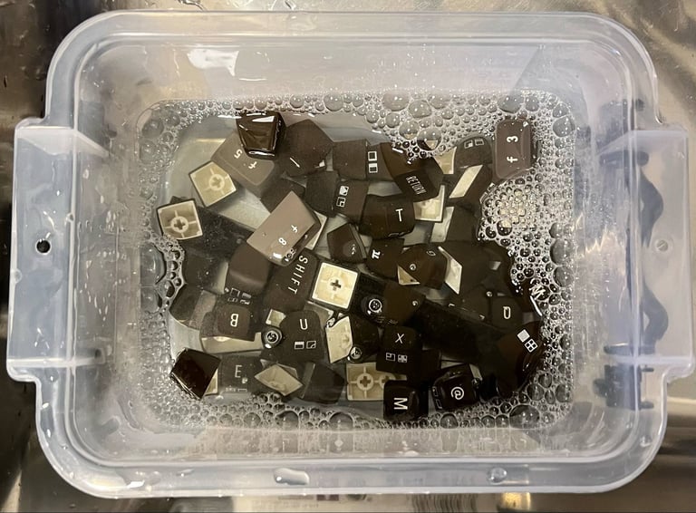
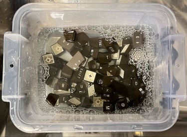
All the keycaps are placed in a box filled with mild soap water for about 12 hours. This will dissolve most of the grease and dirt.
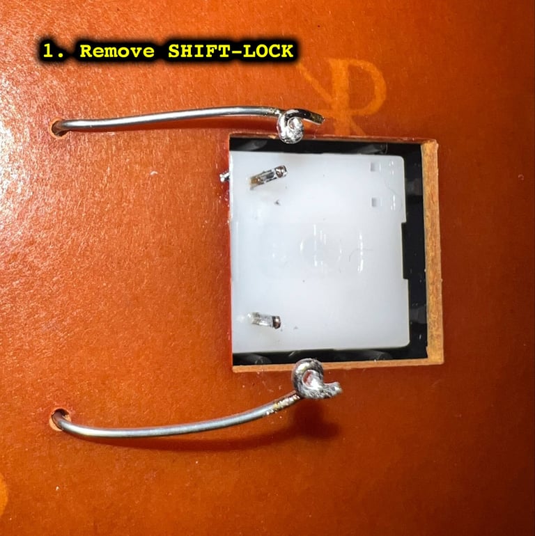
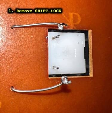
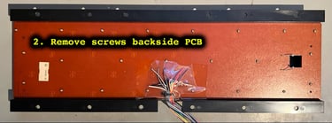
Next, the SHIFT-LOCK is desoldered and pushed out of from the keyboard. With the SHIFT-LOCK out of the way, all the tiny screws holding the backside of the PCB to the plastic bracket are removed.

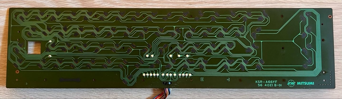
The PCB is of the type Mitsumi KSR-A66YF 56 4021 B-01. And the "B" indicates that this PCB use carbon pads which needs to be treated carefully. The way to clean this type of PCB with carbon pads it to avoid sharp tools and use distilled water (avoid oil and isopropanol). Below is a picture of the PCB after cleaning. Look good as new!
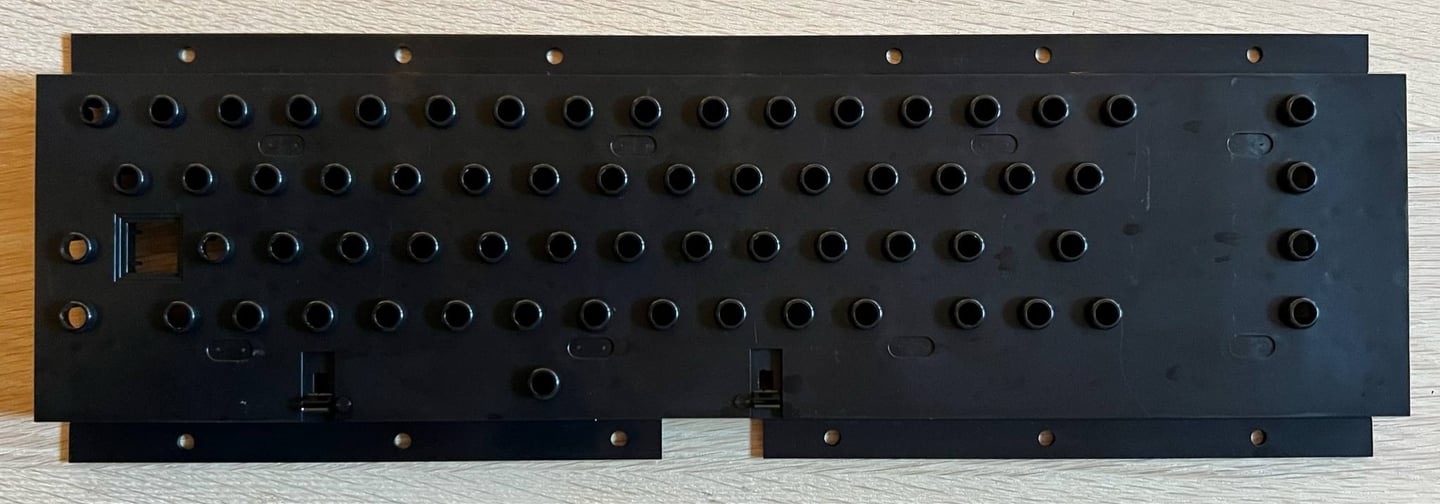
Cleaning the plastic plunger housing is straightforward, and the result is very good. It is cleaned with mild soap water and a clean paint brush. Below is a picture after cleaning. A good as new!
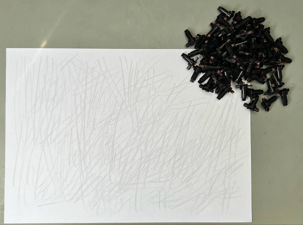
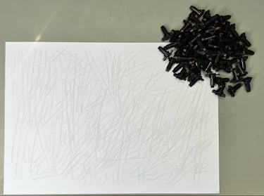
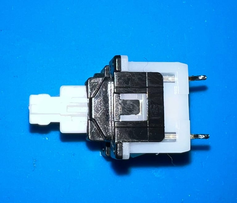
A good way to revive the plungers is to carefully rub them against a clean sheet of paper. By doing this, there is a good chance that the keys will react to key presses just as when they were new. The conductive rubber is often contaminated with at thin layer of grease which would prevent them from working as they should.
The SHIFT-LOCK is cleaned with isopropanol and checked.
Although the keycaps are not very yellowed they are retrobrighted. But this time I try a slightly different approach. Instead of covering the whole of the keycap with 12 % hydrogen peroxide cream, only the top of the keycap is covered with cream. The reason for this is that the front symbols of the keycaps are quite fragile, and will easily come off with the strong hydrogen peroxide cream. Below are some pictures from the process - click to enlarge. The retrobighting is done for about 12 hours (during this period, the cream is applied frequently).
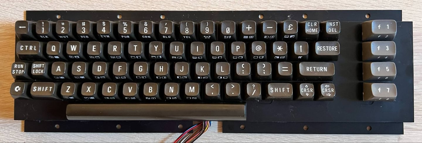
After the retrobrighting all the keycaps are put back. The result is quite good I think! Below is a picture of the keyboard after refurbish.
Mainboard
Visual inspection
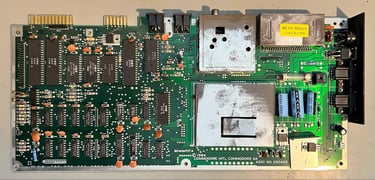
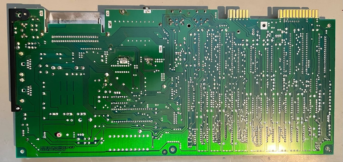
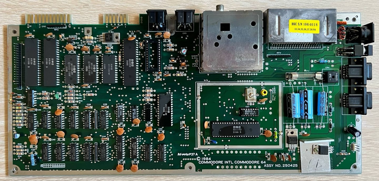
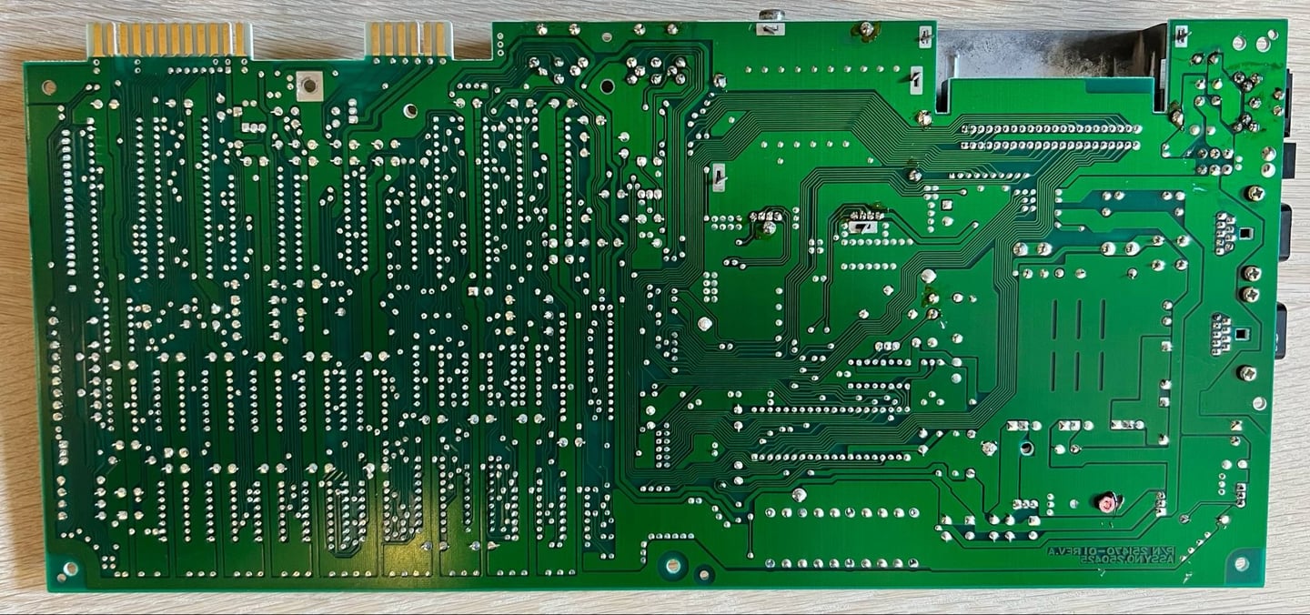
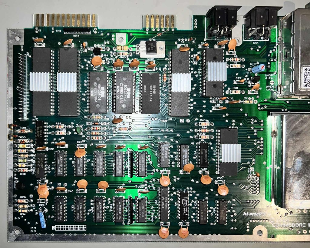
This is an Assy 250425 mainboard 251470-01 Rev A (PCB also marked with "Hi-Pric 37A"). A quite common mainboard found in mid-age Commodore 64 breadbins. Unfortunately, I am aware that these PCBs can be challenging to work with due to poor PCB quality (ripping pads and traces due to desoldering). But hopefully we will not have too much of a problem here.
The mainboard looks to be in overall good condition. There are some dust and grease and some oxidation/corrosion on the VIC-II shield, RF-modulator, user-, datasette-, and cartridge port. But otherwise I can not see any major damage, bulging/leaking capacitors, broken traces/pads or re-work. Some things to note which will be checked/improved later:
The power switch is quite stiff
There are some flux residue on the mainboard, but this is from production (most likely a result of hand soldering)
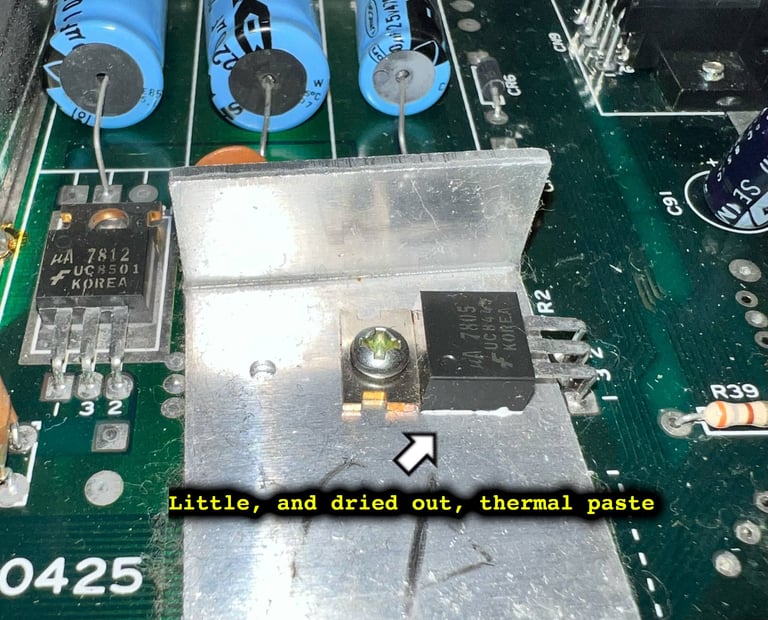
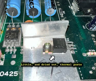
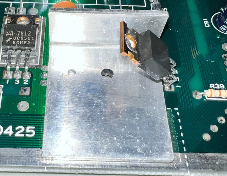
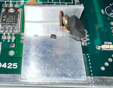
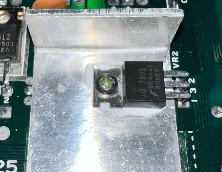
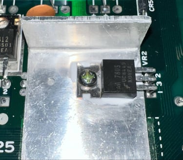
There is very little (and completely dried out) thermal paste between VR2 and heatsink
The User- and datasette ports are quite corroded
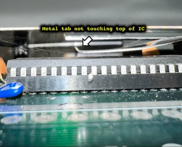
The combined RF-shield and heatsink for the VIC-II is not properly installed. The metal tab which should press towards the VIC-II chip is not touching the IC at all (making this "only" function as RF-shield, but does not contribute to the heat transfer away from the IC)
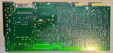
Below are some pictures of the mainboard before refurbish.


In the table below all the custom ICs are listed. And as can be seen from this table is that all original ICs were produced between week 48 of 1985 to week 05 of 1986 so I think we can assume that this Commodore 64 was produced in the winter/spring of 1986.
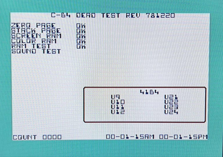
Initial testing
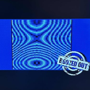
An initial test is performed on the mainboard. This is done with the purpose of checking the initial status of the mainboard - checking for any fault symptoms. In the table below the result are shown.
Below is a gallery of pictures showing some of the screens taken during initial testing. Click to enlarge the pictures.
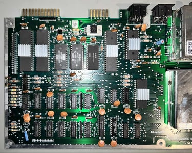
Cleaning the mainboard
Before the repair, and refurbish, continues the mainboard is cleaned. This is done by first removing the socketed ICs (and the fuse), and then washing the mainboard with mild soap water and a paint brush. After cleaning the mainboard is left for drying for a couple of days. Note: the combined RF-shield and heatsink covering the VIC-II is desoldered before cleaning. Below are some pictures of the mainboard after cleaning.

Cleaning the User (CN2)- and datasette (CN3) port
The user- and datasette port are quite corroded. See pictures below.
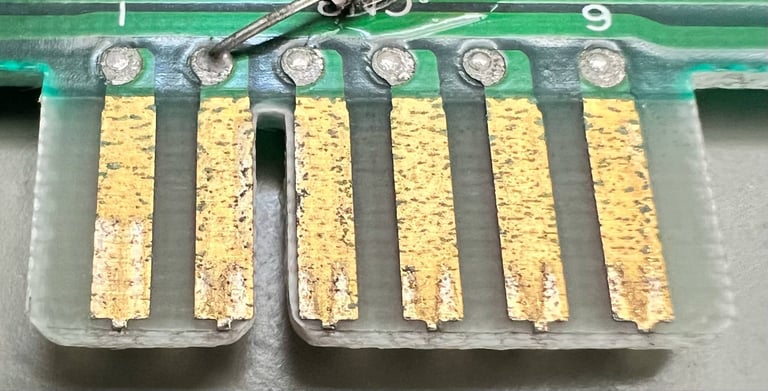
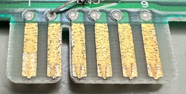
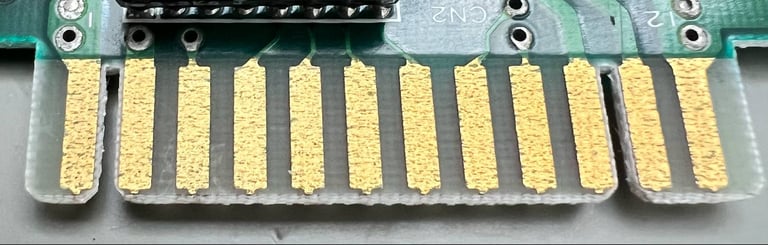

To clean the contacts an old school eraser is used, and some isopropanol. It does help a bit, but it still not too good.
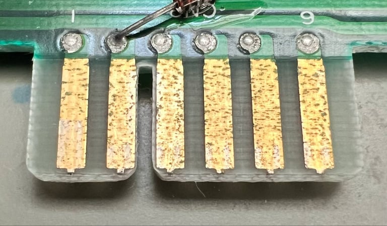

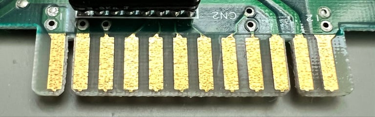

Eventually, the ports are cleaned with a glass fibre pen (I got some help from the Commodore/Amiga Norge Facebook group. Thanks!). Now the ports look way better.

Checking the voltages
For the Commodore 64 to work flawlessly all the different voltages need to present and within acceptable tolerances. A detailed article on the subject can be found in the HOWTO - Checking the C64 voltages. In the table below all the measures voltages are listed (this list will also be updated after refurbishment). All the required voltages are present and within tolerances, so there are nothing obvious wrong in that area.
Mainboard - Repair
Faults hypothesis
What could cause the machine from working? Based on the symptoms, and the results from the cartridges, I think it is likely that the Kernal ROM is bad. This is based on the following observations:
When the machine is cold (all capacitors have drained their stored energy) the machine shows a garbled screen at boot-up. But even if this screen is garbled, we can see that:
There are two characters used in the "garbage": a "@" and "stair" symbol. These symbols represent the value of $00 and $FF respectively, which would indicate that the VIC-II is reading a non-initialized RAM at $0400. Also, we see that the sideborders are present indicating that the VIC-II is working.
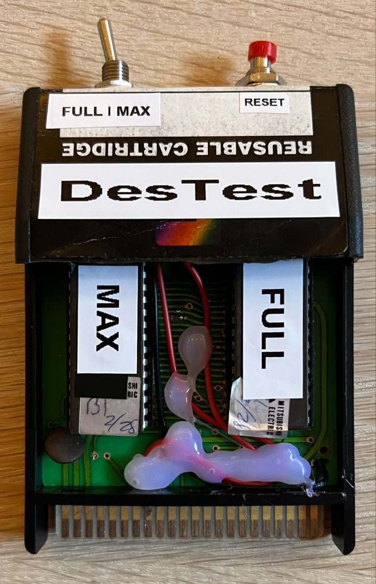
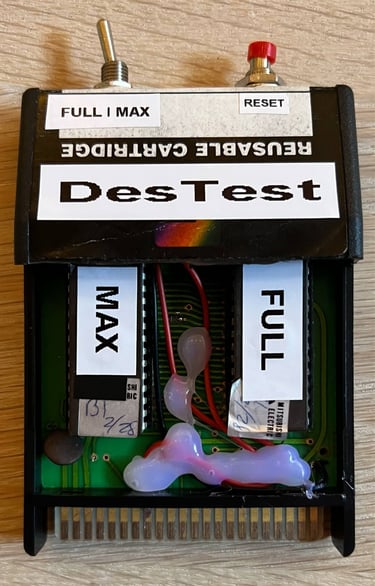
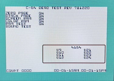
Both the DeadTest and the DesTestMax utilise the "Ultimax" cartridge mode which bypass the Kernal-, BASIC- and Character ROM. And these both work fine. This is a indication that the CPU, RAM (first 4k), VIC-II and PLA works.
The Diagnostics cartridge does not run. This cartridge require all the ROMs to work (including the Kernal).
The DesTestFull works when the machine is cold. And when it works it shows both changing, and a not identified, Kernal ROM checksums.
I think that the DesTestFull cartridge is really valuable here. There is obviously something happening either with the Kernal ROM itself, or some surround circuitry. I reached out to the person who has developed the DesTestFull (and Max) cartridge, Matthew Desmond, asking to what extent the Kernal ROM needs to work for the DesTestFull to function. And it turns out that it does use just a tiny part of the ROM code (the reset routine at $fce2 been called from $fffc/$fffd). A great thank you to Matt for helping out here! And for making a really great cartridge(s)!
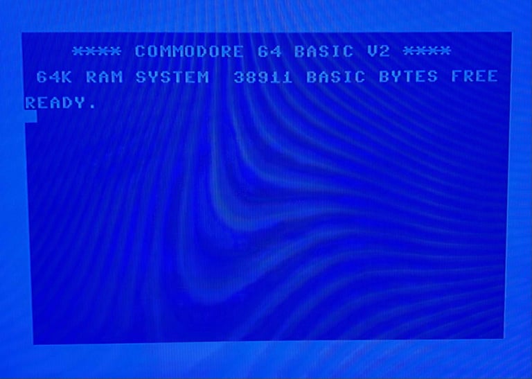
In an attempt to try to "fix" the problem the Ultimate II+ cartridge is used. With this cartridge an alternative Kernal ROM image can be used which will override the machines own internal Kernal ROM. And guess what? By using a standard CBM Kernal as "alternative" the machine boots straight up! Nice!
Below is a picture of both the "home-assembled" DesTestMax and DesTestFull cartridge - and the famous blue screen now showing with the use of the Ultimate II+ cartridge.
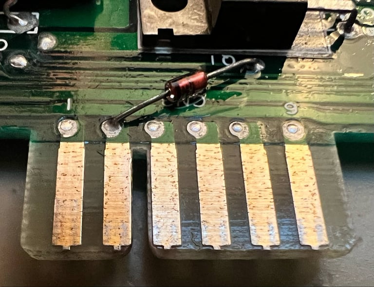
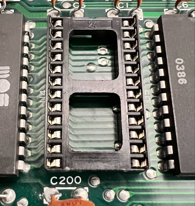
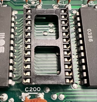
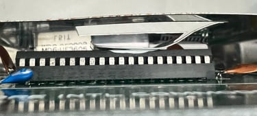
Desoldering and replacing the Kernal ROM (U4)
I think we have a strong case for that the Kernal ROM is marginal. But to prove it (or disprove it) the Kernal ROM needs to be desoldered and replaced with a known-working IC.
To make sure that I desolder the most careful way, the following process is followed:
Some fresh Kester Sn63Pb37 solder is added to the Kernal ROMs 24 solder points. Soldering (and desoldering) temperature is set to 340 degrees Celcius
Desoldering each pin by using soldering iron on the top side of the mainboard, and at the same time desolder each pin from the bottom side (since I do not have three arms the mainboard is held vertically in a clamp)
The solder/desoldering is done approximately 2-3 seconds on each solder point
When all the solder points are cleared (or as clear as they can be) the IC is CAREFULLY lifted with the usage of hot air
The desoldering is successful - no pads or traces were lifted as I can see. See pictures below.
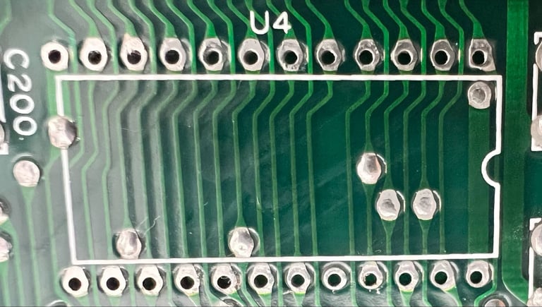

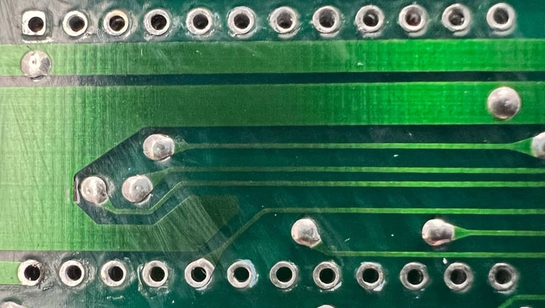
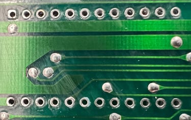
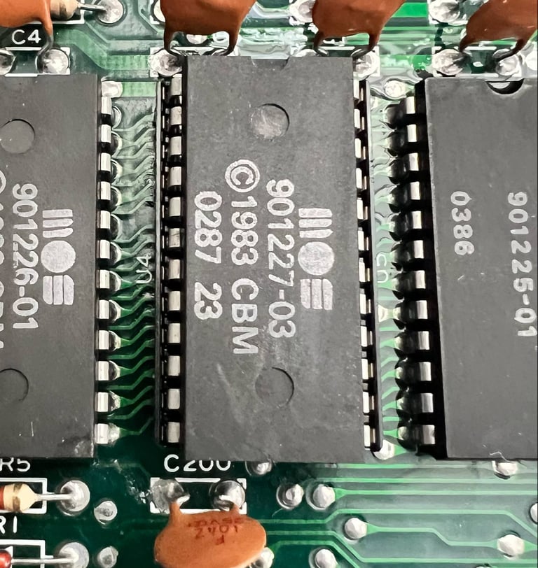
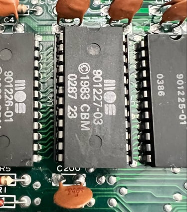
A new 24 pin dual wipe socket is soldered in place, and a "new" MOS Kernal ROM 901227-03 is installed in the socket. The new Kernal has a date code of week 02 in 1987 this is quite close to one year younger than the original Kernal ROM.
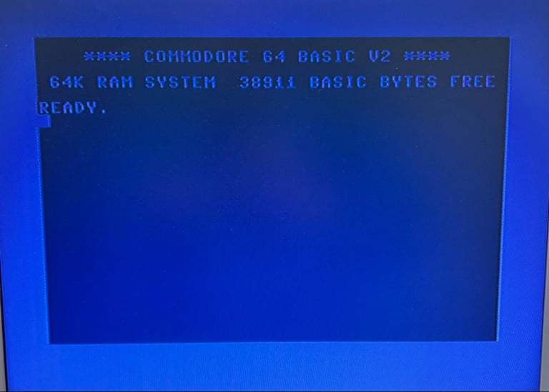
<DRUMROLL>
Does the blue startup screen appear now on power-on? Is this fault fixed? This is the moment of truth!
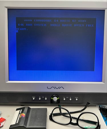
YES! It shows the beloved blue startup screen! 38911 BASIC BYTES FREE!
</DRUMROLL>

A big shout ut to Matthew Desmond, the creator of the DesTestFull and DesTestMax cartridges. With the DesTestFull cartridge I was able to get indication that the Kernal ROM was marginal. Nice!
UPDATE: The symptom with the garbled screen is not uncommon to see with the Commodore 64. But to see this symptom caused by a marginal Kernal was new to me. To help others with their fault finding on Commodore 64 a picture of the symptom was sent to The Pictorial C64 Fault Guide which now has included this on their webpage.
Mainboard - Continued
Initial testing - continued
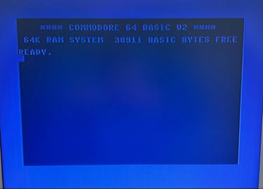
Are we out of the woods yet? Now that the machine boots to blue screen, with 38911 BASIC BYTES FREE and a flashing cursor the main ICs can at least bring the machine to good position for further testing.
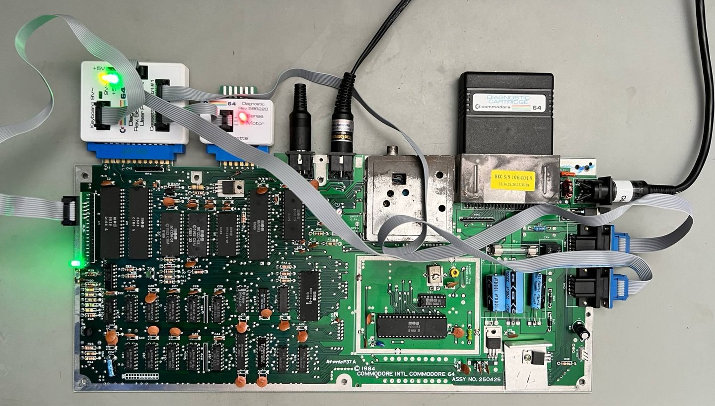
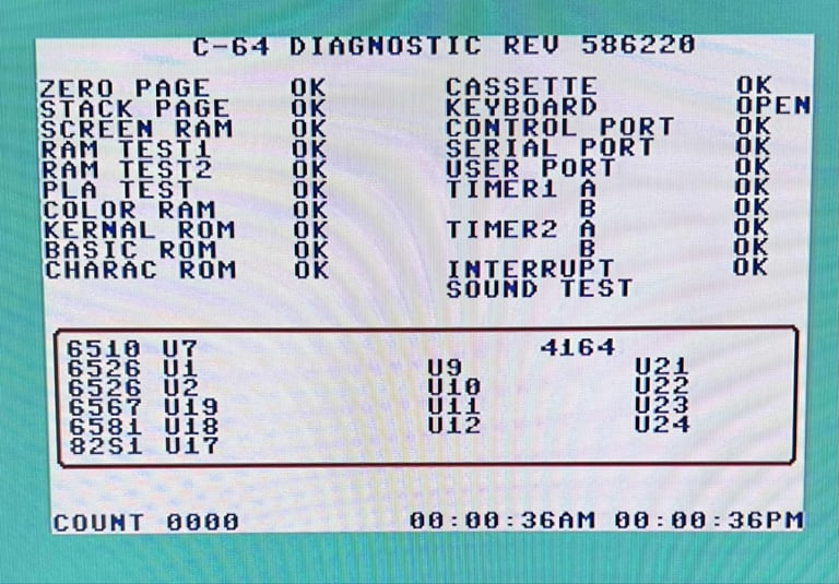
Next, the Diagnostic cartridge with the harness attached is used.

And, sure thing, another list of issues are identified:
Cassette communication report BAD
User port report BAD
Interrupt request and handling report BAD
Both the 2 x CIA and CPU reports BAD
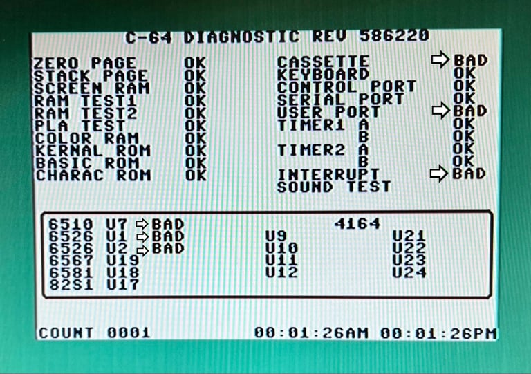
I have a strong feeling that this is due to the quite corroded user- and datasette port. These are now cleaned, again, but this time with a glass fibre pen. And now the testing pass everything.
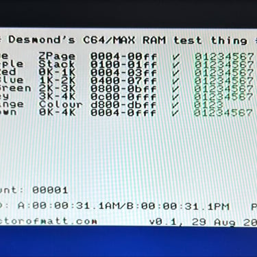
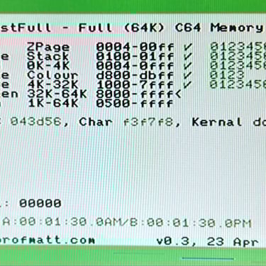
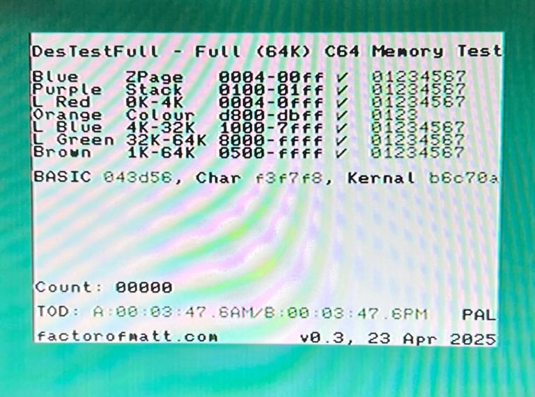
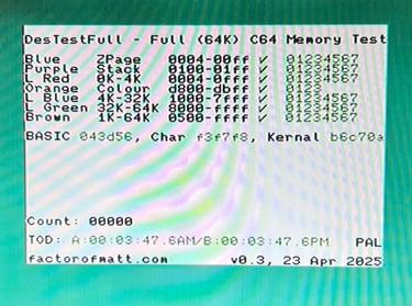
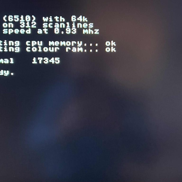
As the final part of the inial test the machine is tested with the DesTestFull cartridge. This will test the whole 64kb of RAM in the Commodore 64 using the March-B test algorithm. As can be seen in the picture below, all tests pass with flying colours.
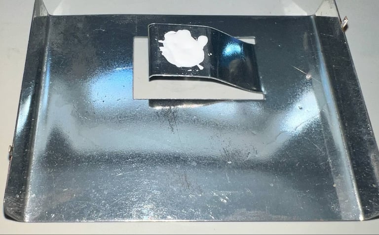
Replenishing the heat paste (VR2)
The heat paste between the 5V voltage regulator and heat sink is completely dried out. Since the purpose of the heat paste is to help the heat transfer it is good practice to remove the old paste and add some new.

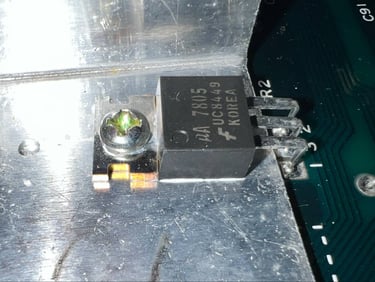
To replenish the heat paste the small screw (and 5 mm nut on the backside) are removed first, and the voltage regulator is carefully tilted. Now the heat sink can be pulled out (and cleaned). Some new heat paste is added to the heat sink and backside of the voltage regulator, and everything is put back.
Adjusting the heatsink / RF-shield (VIC-II)
As discovered as part of the visual inspection, the metal tab on the VIC-II heatsink is actually not touching the IC at all. This is taken care of by doing the following:
Bending / adjusting the metal tab on the heatsink so that it touches the IC
Applying some fresh heat paste between the metal tab and the IC. This will help on making good thermal contact between the top of the IC and the bottom of the metal tab.
Below is some pictures from the process, and the metal tab (and heat paste) in place. You could argue that the metal tab should be a bit more straightened, but this was as good as I managed. Bending it more could break the metal.

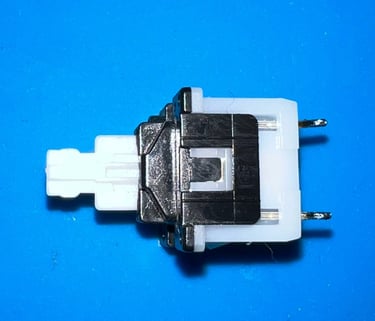
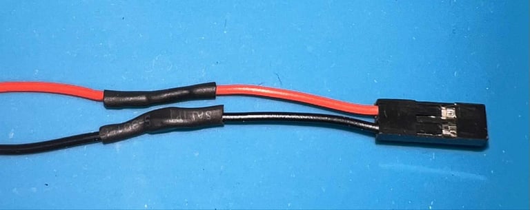
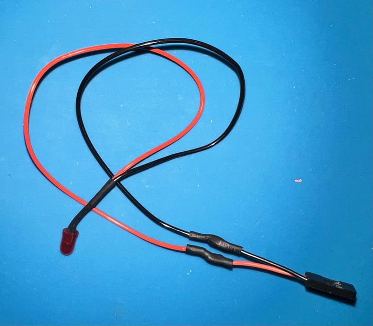
Repairing the LED wires
The black wire is ripped out from the flat connector. Instead of repairing the old connector, a new two-pin connector is soldered to the wires.


Adding heatsinks
As an attempt to reduce the risk of failing custom MOS chips some heatsinks are added to some of the ICs; the SID-, CPU-, PLA-, and both CIA chips.
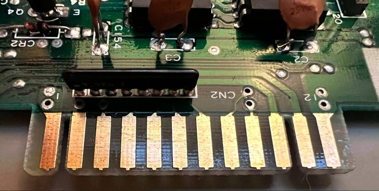
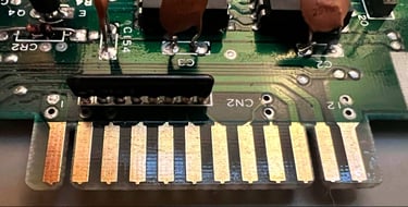
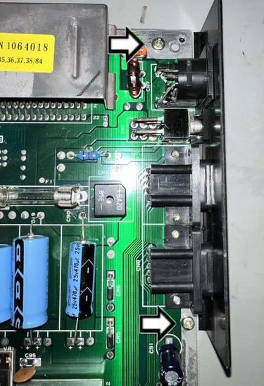
Fastening the port metal bracket
The metal bracket covering the controller ports and power connector is not mounted to the PCB. To mount the metal bracket to the PCB two small machine screws are inserted.

Testing
Proof is in the pudding - does it work?
Testing is done through three main stages:
Testing the basic functionality and chips
Testing the complete set of custom ICs and I/O ports
Testing by using the machine playing demos, games etc. accessed by both floppy and datasette to verify correct operation
Basic functionality and chips
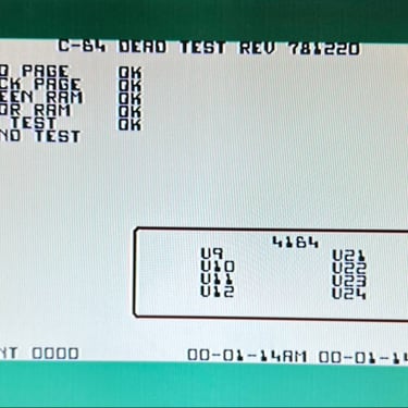
First test is done using the Dead Test Cartridge. This test doesn´t test all the functionality of the Commodore 64, but it does test the basic functionality of the major chips such as the CIA #1/2, CPU, VIC-II, PLA, RAM and SID. As the picture shows below the test is passed.
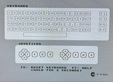
Next test is to power the Commodore 64 to the blue boot up screen and also check the keyboard to make sure all keys works as they should. The test is passed; all keys works and 38911 BASIC Bytes Free.

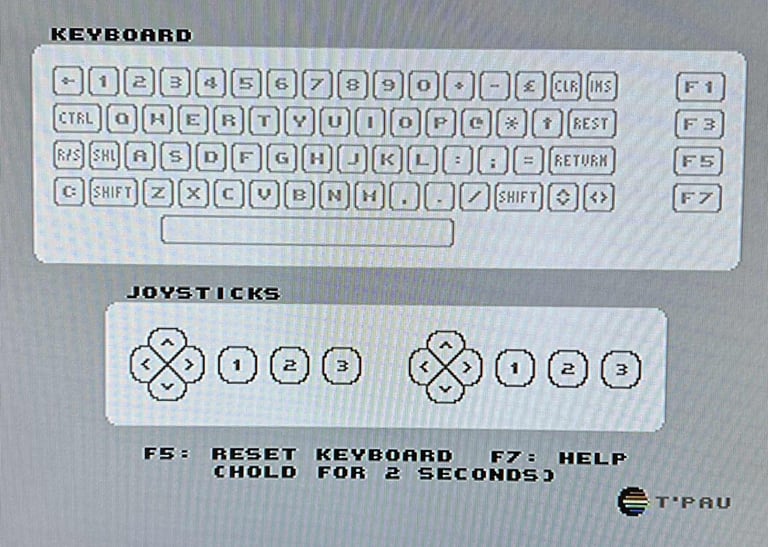
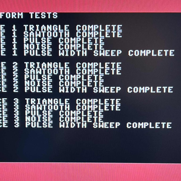
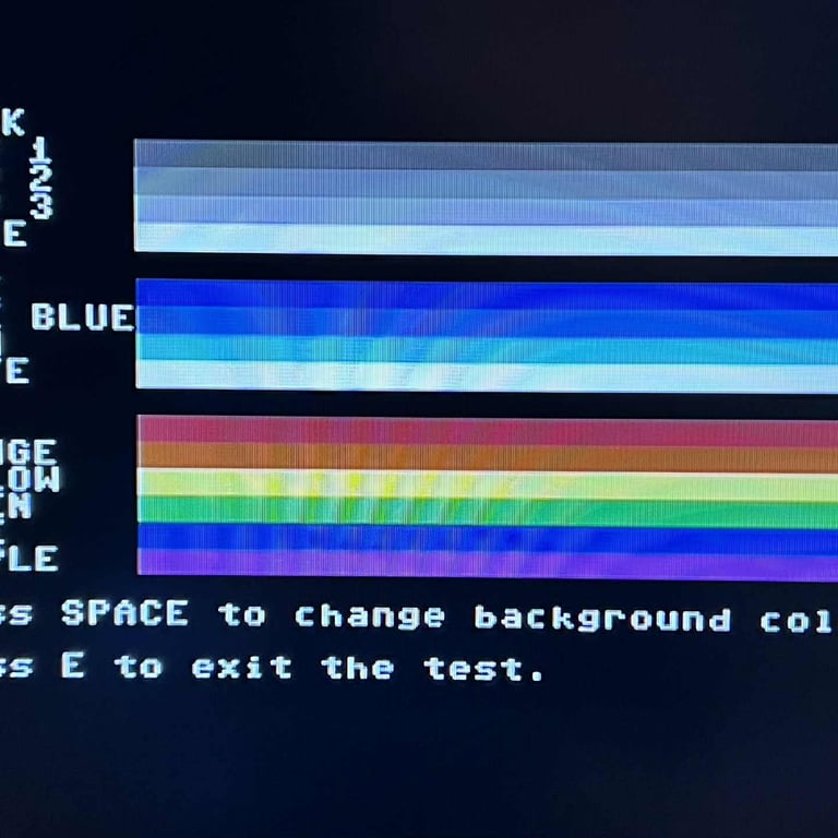
The basic functions of the VIC-II, SID and RAM is tested with 64 Doctor, Commodore 64 SID tester and MemTest64. Note that this is to be considered as basic functionality - more advanced (?) functionality such as sprite handling / collision detection / advanced audio will be tested later. But the basic tests pass without any detected faults (click to enlarge).
Diagnostics test with harness
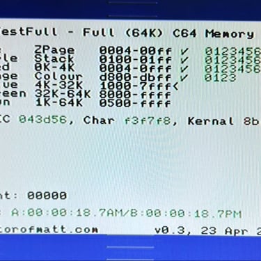
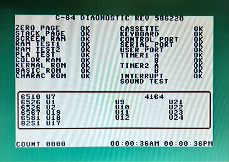
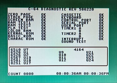
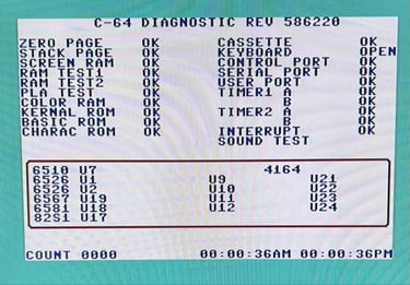
To test all the custom ICs, and I/O ports, the Diagnostics cartridge is used. The Diagnostics cartridge is very valuable when the complete test harness i installed as in "everything" is tested formally. As can be seen from the picture below, no issues are identified.
Extended testing
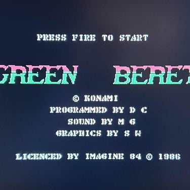
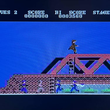
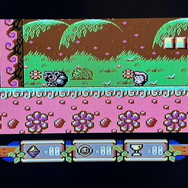
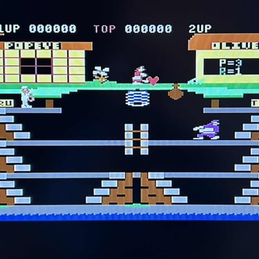
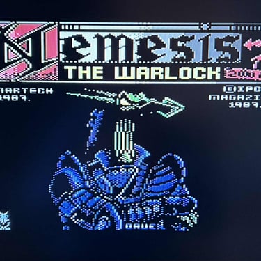
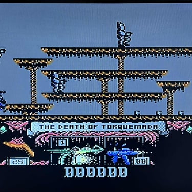
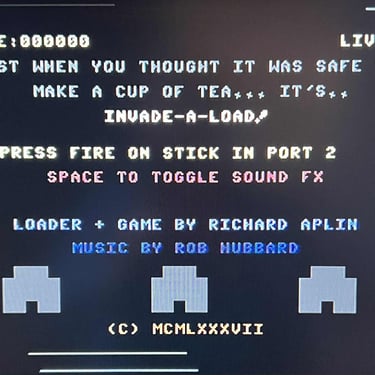
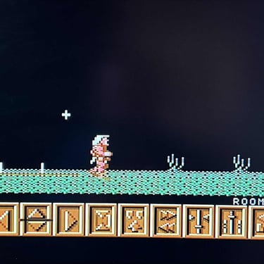
Knowing that the basic functionality of the machine works I continue the testing by using the Commodore 64 for normal operations; playing some games, watching demos, loading from datasette and floppy and using a cartridge. I can not find any issues with this machine. I also pay special attention to the video to make sure that there are no glitches in the graphics - I can´t see any abnormalities. Below is a gallery with pictures from the testing.


Final result
"A picture worth a thousand words"
Below is a collection of the final result from the refurbishment of this C64 breadbin. Hope you like it! Click to enlarge!


"Are you keeping up with the Commodore? 'Cause the Commodore is keepin up with you!"
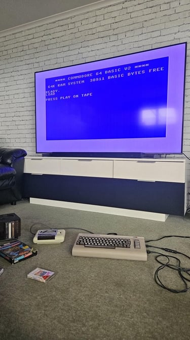
Below are some pictures of the Commodore 64 back at the customer´s home!

Banner picture credits: Evan-Amos