

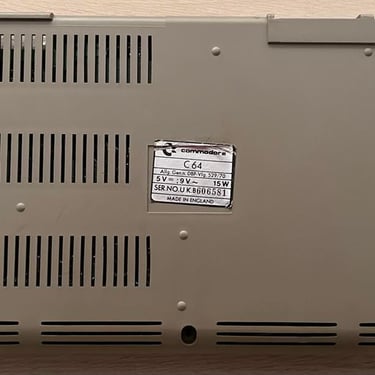
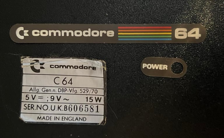
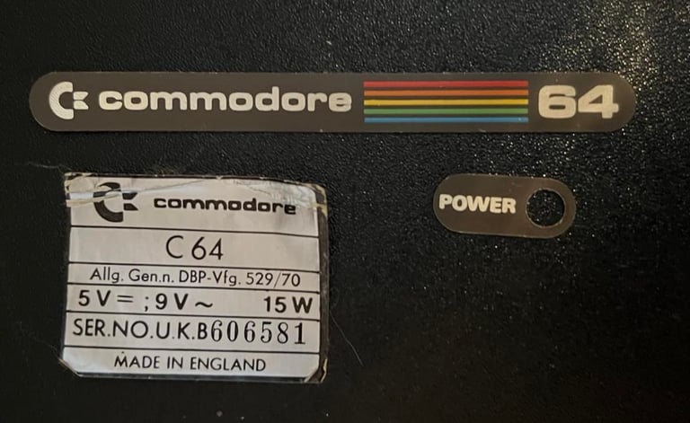
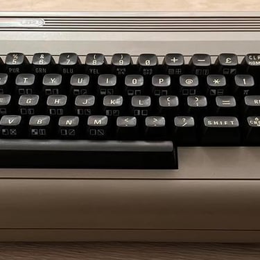
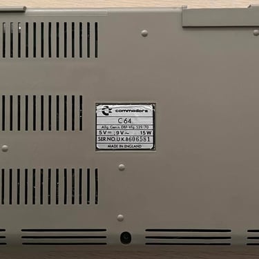
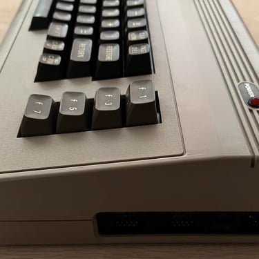
C64 Breadbin
Ser. No. 606581
Assy 250407
Artwork 251137 (REV C)
Refurbishment plan
To refurbish this C64 breadbin the plan is to do this trough the following steps (some of them in parallell):
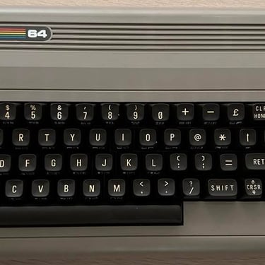
- Clean and restore the keyboard
- Clean and remove stains from the chassis
- Refurbish main board (cleaning, checking, repairing, replacing capacitors and voltage regulators etc.)
- Recap RF-modulator
- Verify operation by testing
Below you will find some pictures before I begin the refurbishment (click to enlarge). It is quite dirty, but otherwise looks intact.
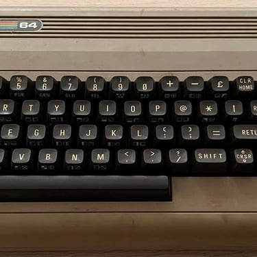
Keyboard
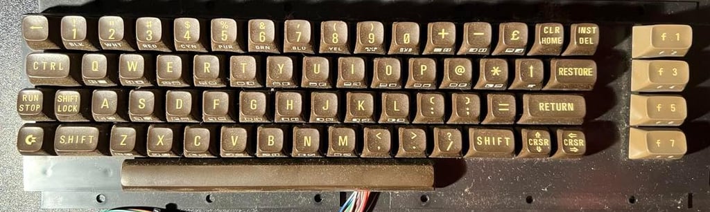
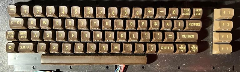
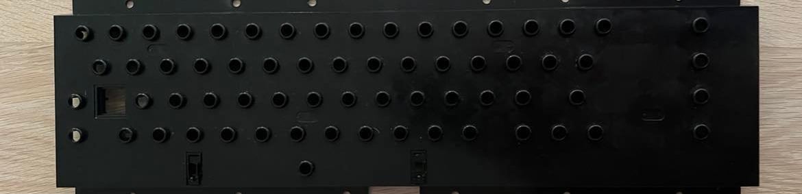
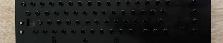
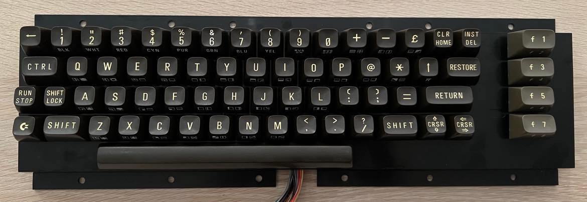
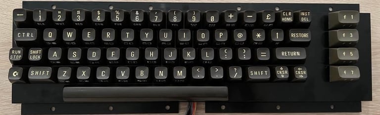
The keyboard looks fine. It´s very dirty, but it is complete and I can´t see any damage to it. So this will probably work fine after a thorough cleaning. Below is a picture of the keyboard before the cleaning.
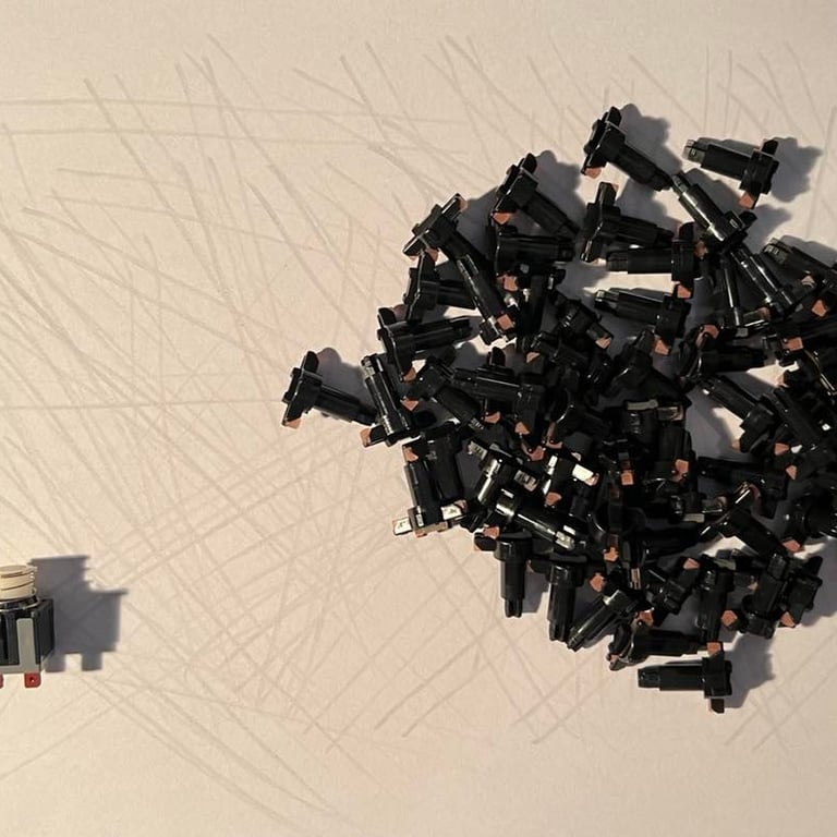
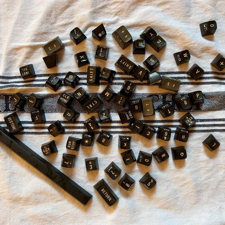
All keys are removed with the keycap puller. I´ve removed the keys from keyboards quite a few times, but I´ve never before experienced keys that are so hard to remove. They are really hard to get off. Nevertheless, all keys are removed and no plungers broke in the process. Note that the spring for the spacebar is different from the rest!
To further disassemble the keyboard all screws at the backside are removed, and the two wires connecting Shift Lock are desoldered. Note that you need to push from the backside to get the Shift Lock key out from the case.
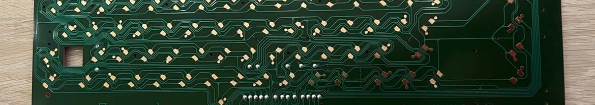
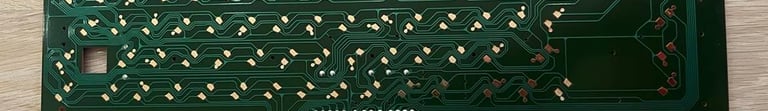
When all parts are disassembled I clean the keys and the plastic bracket with mild soap water only, and the PCB with isopropanol. After cleaning the PCB looks very nice and no sign of corrosion so this C64 looks to have been stored in a dry environment.
The keys are cleaned with luke warm soap water. The grease come off quite easily. The Shift-Lock key is cleaned with a micro fibre cloth. All the plungers are gently dragged over a clean paper sheet. I do this to remove old dust and residue. Other "refurbisher" might clean them with water and/or isopropanol, but my experience is that this could damage the plungers. That said, both methods can damage the plungers if they are marginal. I always check the keyboard during the testing phase and if any plunger is damaged new ones will be ordered.
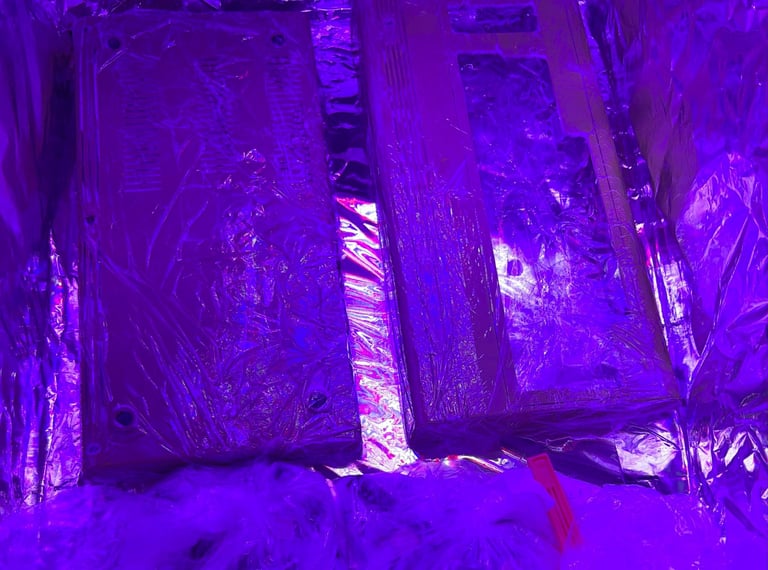
After the keys are cleaned I put them in a bag filled with 12 % hydrogenperoxide (cream) and expose the bag to UV light for about 7 hours. I find it hard to get them back completely to the original white color, but I think the result is quite good nevertheless.
Below is a picture of the restored keyboard in all it´s glory. Click to enlarge.
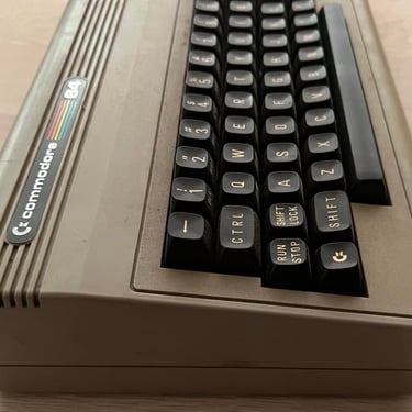
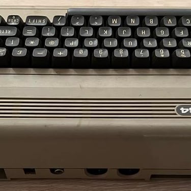
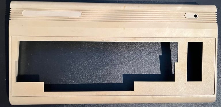
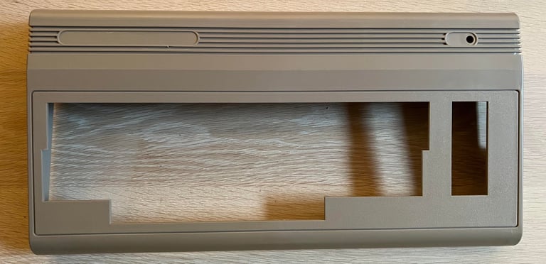
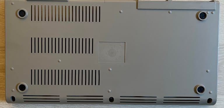
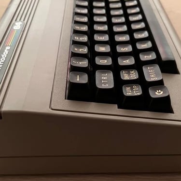
Chassis
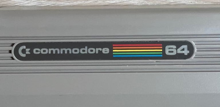
The chassis is very dirty, but otherwise intact as far as I can see. While investigating the chassis I notice something funny: the Commodore 64 badge is too large (?) to fit the area. Never seen this before, but I can only guess that someone have removed the original one and replaced it with a new (but original) badge. But when replacing the badge the new badge is a couple of millimeters too large... Don´t quite now how to fix this yet. Either grind down a bit on each side, or try to get a new one which fits.
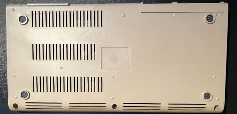
Top cover is removed by unscrewing the three screws at the bottom. This reveals that two of the brackets at the end is partially broken, and the last bracket is completely broken. This is more or less the normal situation for these old machines. My opinion is that this is not any big problem at all. As long as the screws are in place, and that some of the brackets are partially there the chassis locks enough to the bottom cover.
The LED is carefully removed but removing the small clip from the bottom side of the top cover, and the rubber feets at the bottom cover is also removed. The both the logo- and the power badge is removed. The way to remove these are to apply some heat from a hair dryer and then gently lift then away with a sharp knife. An advice here is to not rush this operation. Blow hot hair in circular motion from a distance around the badges and let the heat allow to melt the glue. If you rush it you could either bend the badges or overheat the plastic. The bottom sticker is also removed. This already looks quite withered but no further damage is done while removing it. Pictures of the removed badges and stickers below (click to enlarge).
Below you will find pictures of the top- and bottom cover before the cleaning process start. Click to enlarge.
The top- and bottom cover is placed in luke warm soap water for about two hours, and then cleaned with a non-scratching dish brush and left to dry. This is just to remove the worst dirt. After this I continue cleaning the chassis with a combination of isopropanol, baking soda and glass spray (used separately) to remove the toughest stains. The top- and bottom cover is also quite yellowed in some areas so I decide to retrobright it. In this process I use 12 % hydrogenperoxide cream and UV light (the keys are also put in a plastic bag filled with cream to lighten them also). The process takes about 7 hours.

I´m very pleased with the result. As far as I can see all the major discoloring are gone.
I can´t find a new metal badge from the online shops (at least to a reasonable price). So instead, I decide to grind it down with a small metal file tool which works just fine I think! See picture below for the result of this small grinding operation.
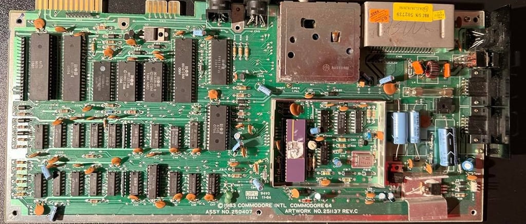
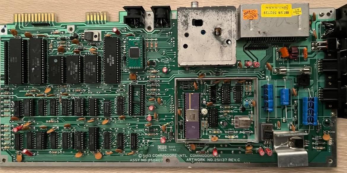
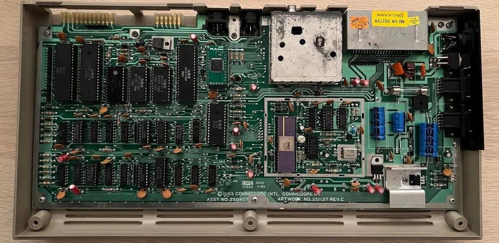
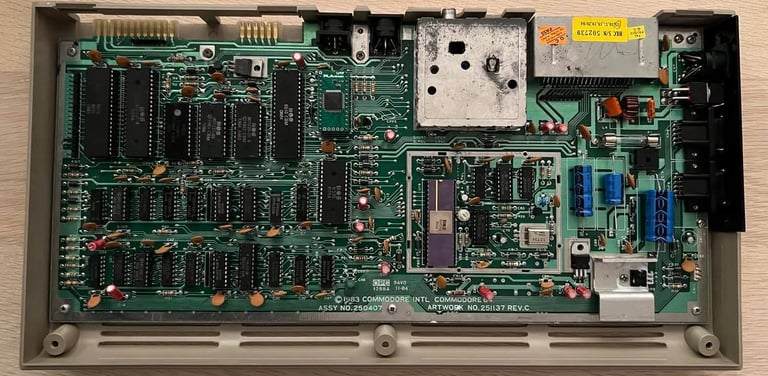
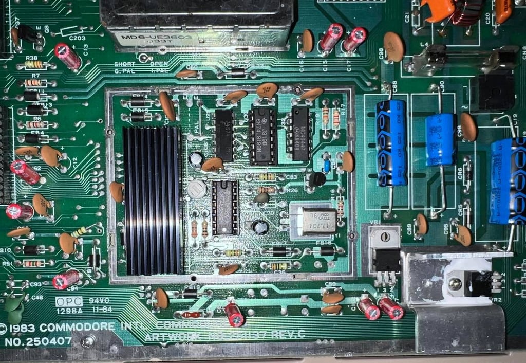
Main board
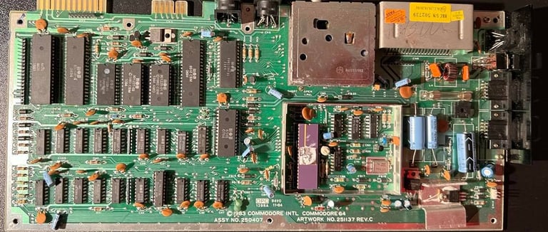
The main board is assy no. 250407 artwork no. 251137 Rev C. If you are interested you can find details about this main board at Retro Rewind.
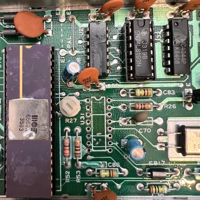
Before powering up the board I do a visual inspection and noticing:
CIA #1 is socketed, but CIA #2 is not. The CIA #2 is from week 04 in 1984, and CIA #1 is from week 15 in 1983. To me this points in the direction that CIA #1 was replaced at some time
Character and Kernal ROM are socketed, but the BASIC ROM is not. Indicates that these two have been replaced at some time (?)
Many different RAM chip vendors; MT, NEC, Hitachi(?) and Mitsubishi. Typical Commodore to use all kinds of RAM vendors. But, MT RAM chips are notoriously bad. They might work, but the are famous for failing when old. Should be replaced.
Two MOS 7708 and one MOS 7711 logic chips. These chips are also quite famous for failing with age. Should be replaced.
All electrolytic capacitors looks ok (not leaking). Nevertheless, they are almost 40 years old and are likely to have dried up.
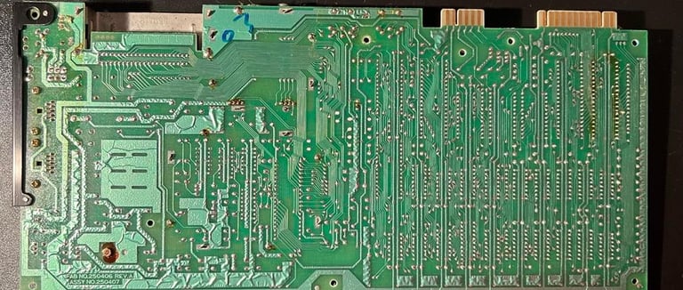
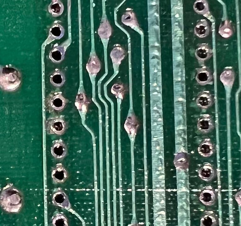
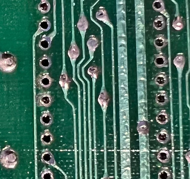
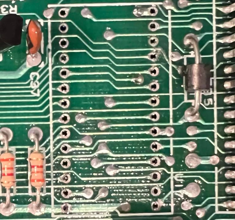
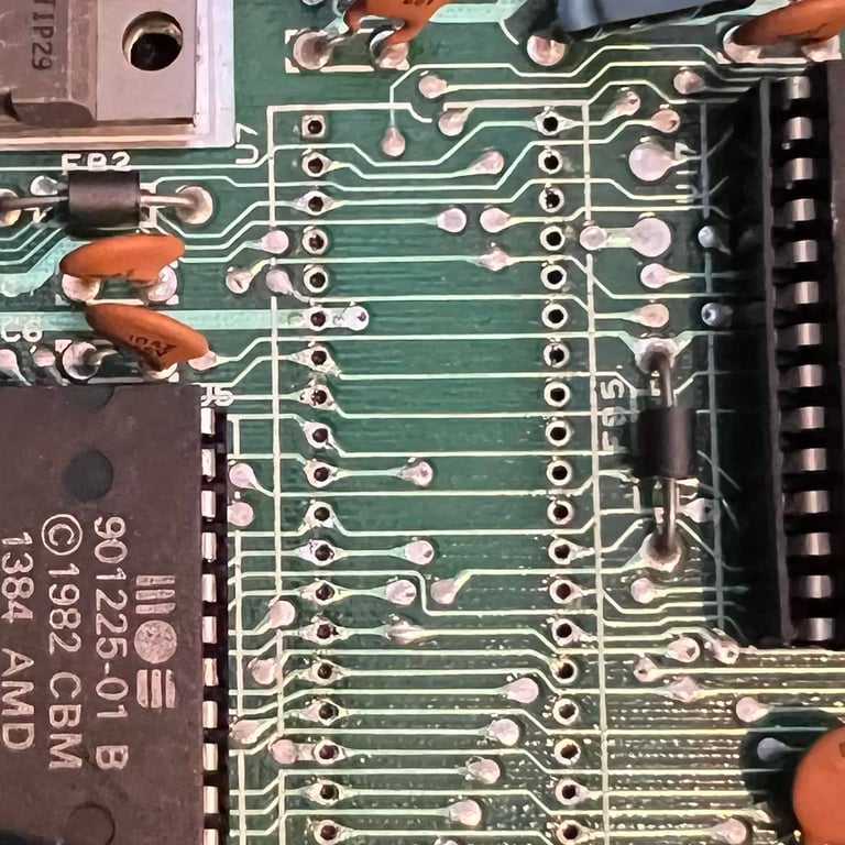
Backside of the main board looks ok. It´s quite dirty, but I can´t see any corrosion. I see quite some flux residue around CIA #1 so this has definitely been replaced. At the same time I see that the area around the Kernal- and the Character ROM looks mint. Maybe these were socketed at production actually?

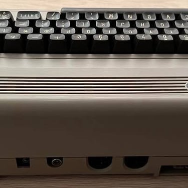
The last thing I check before power up is to check for shortcuts:
Between 5 V CAN output and ground (7805)
Between 12 V output and ground (7812)
Between 5 V DC and ground (user port)
Between 9 V AC and ground (user port)
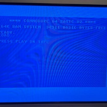
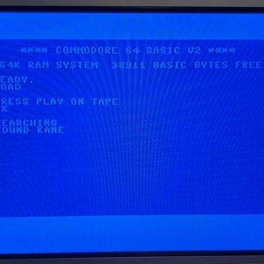
None of these show any sign of shortcuts - so it´s time to power on (but I remove the SID chip - this is not required for the C64 to start).
What a surprise! BLACK SCREEN! Well, this is also quite normal - so I need to do some fault finding. Before I start this process I wash the main board with luke warm soap water and a paint brush. This will make it way easier to detect any broken traces or corrosion, but also a bit more nice to fault find a clean board than a dirty one. I let the board dry for 48 h before starting fault finding.
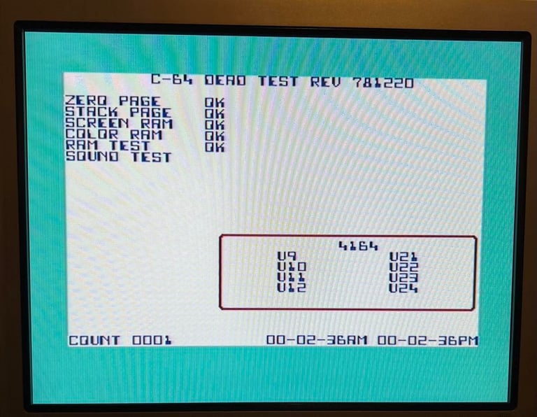
Voltages looks ok, but I notice that the Kernal ROM gets quite hot. It´s not super-hot, but still I think I need to remove this out of the socket. It´s time for the Dead Test Cartridge to see if we can detect anything.
The Dead Test reveals nothing. The Kernal might be bad, but there is obviously something else bad here. There is video signal because I can see on the TV that it gets some kind of signal. I will do some testing with my oscilloscope and multimeter. My prime suspects are:
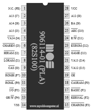
MOS PLA (906114-01)
MT RAM chips
MOS 7708/MOS 7711
MOS 6510 CPU
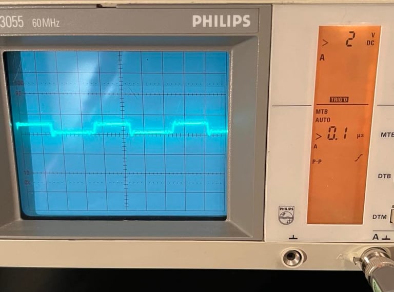
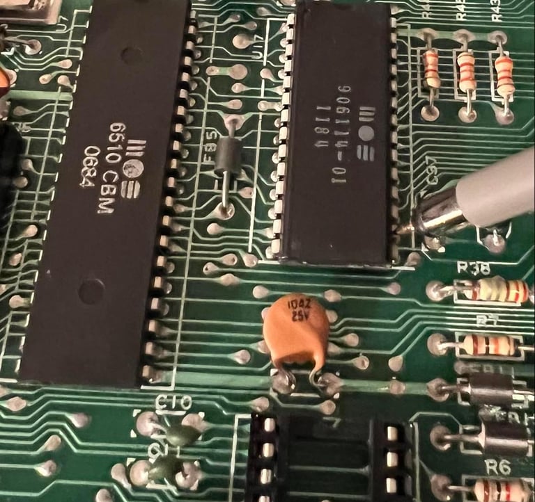
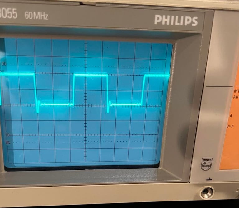
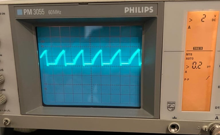
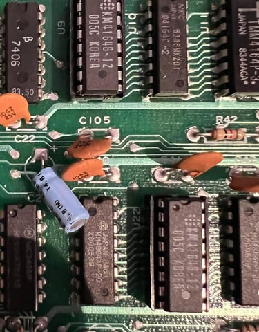
I use the oscilloscope to probe the pins of the PLA. What I´m looking for are signal levels which are "stuck" on odd levels: signals that are something else than high (~5V), low (0 V) or oscillating between 0V and ~5V. And I notice that pin 16 is looking odd. Could this be the problem? It looks to be a pulse with voltage levels between 0V and 1V which doesn´t look correct. See picture below.

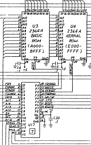
When checking the PLA pinout I see that this pin is used to control the Kernal chip select (CS). Could this strange behavior also cause the Kernal ROM chip to heat up? This points me in the direction that the PLA is bad. As far as I can see from the schematics pin 16 on the PLA (Kernal CS) is connected directly to the Kernal ROM (CS). So there are no other chip than can pull this line down.


There could of course be several problems with this board, but I will first try to desolder and replace the PLA to see if that has any positive effect. I desolder using a combination of both the desoldering gun and hot air. I manage to remove the chip without (as far as I can see) lifting any pads or traces. See pictures below.

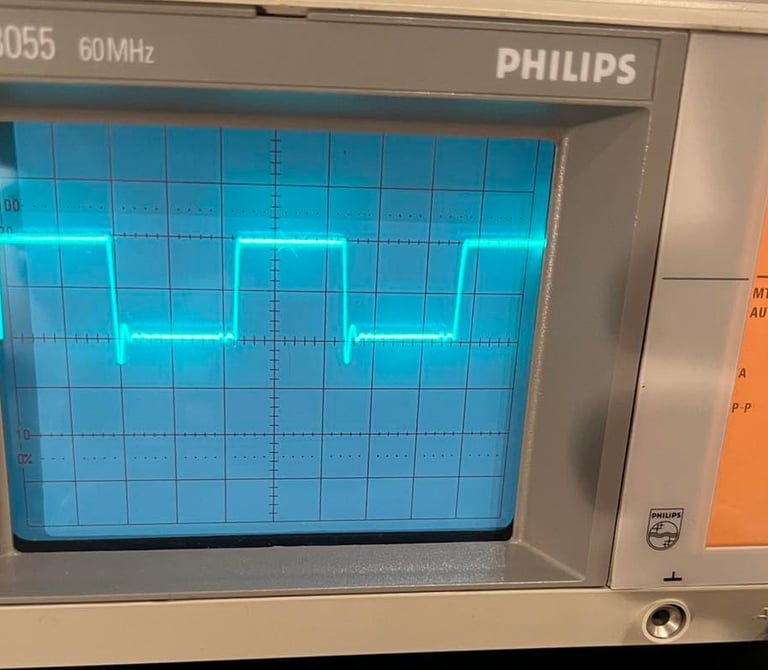
A new socket is soldered back in, and I test with a known good PLA to see what happens. And the result is ... eh... a semi-black screen. It´s black but with some flashing lines and colors. Looks completely random. But I check with the oscilloscope and see that the voltage levels at pin 16 looks good know!
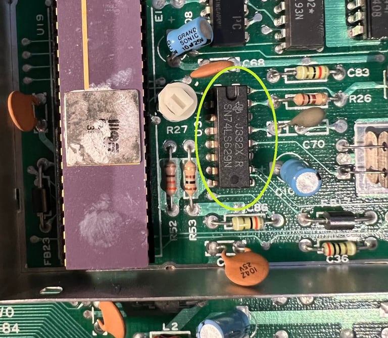
I test the old PLA in another C64 and get the confirmation that this old PLA is dead (black screen). So I need to order a new PLA and keep on the fault finding! It might be a red herring, but I read the following on retroleum.co.uk when a 74LS629 is failing: "Common issues when faulty: Black screen, rolling rainbow colour patterns in both screen and border".
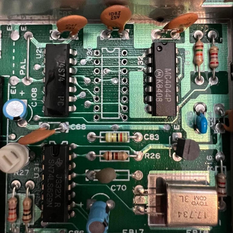
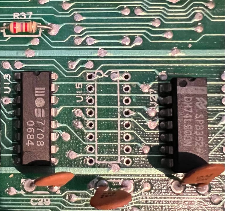
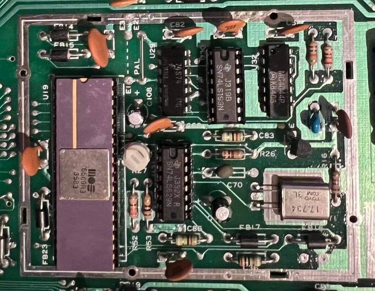
It could be that there is something wrong with the circuitry around the VIC-II chip. I will use the scope and compare the signals on this 74LS629 with a known working C64. If I see anything different I will desolder and replace this. See picture below for the position of this chip.


I use the oscilloscope to measure both the 74LS629 and the circuitry around the VIC-II. I compare the signals with a good known working C64 with the same assy number. I can´t really see anything that looks wrong. That does not mean that it´s not wrong, but I will wait with the desoldering to see if I can find anything more suspicious.
Who you gonna call? Ghostbusters! Well, no... But when in trouble ask for help! So I post a message at the Commodore/Amiga Norwegian Facebook page (https://www.facebook.com/groups/CommodoreNorge) asking for advice! The value of having an arena to ask for help and discuss these matters are invaluable. It´s not always that you get THE answer, but when people are working and thinking together magic occur. Some takeaways from the discussion:
Verify that the VIC-II works
Test both the CIAs
Check RF-modulator
Verify connections from PLA to the board
I start with the first one checking the VIC-II chip. I remove it from this board and put in a known working board. And the VIC-II works! So that is ruled out for now. I will remove the RF-modulator at some stage also (to recap it). But I´ll wait for that operation later. One of the CIA chip is socketed so I remove that also, and test it in another C64. And this also works. I will also wait with desoldering the 2nd CIA chip.
While using the scope I notice something: the IRQ pin on the VIC-II chip doesn´t send interrupt requests to the CPU. The reason why I think this is strange is that I actually thought that there was ALWAYS a signal on this pin. The function of this IRQ signal is to say to the CPU: "hey, I´ve reached a certain raster line". And which raster line this is will be set by writing the value to memory address $d012. So let´s say we would like the VIC-II to send an interrupt request at rasterline 120 we could do this in assembly like this:
lda #120
sta $d012
But does this mean that the VIC-II on power on will NOT send ANY interrupt request by default? Like it´s complete silent until a value is written to $d012? That seems to me very strange, but... could that point in the direction that the CPU never get in the position to actually write to the VIC? Is the CPU broken? Or the glue logic and/or RAM chips are bad? I could be on a wild goose chase here now, but a dead IRQ signal is telling me that there is something very broken here... Also it points in the direction that this is what I call a "digital" issue and not an "analog". It might look analog with the flickering screen, but it might be just the end result - the root cause is something completely else.
Now what? I really don´t belive that the CPU is broken, but I need to rule it out. In addition to the missing IRQ signal there is also another hint pointing in the direction of a broken CPU: the dead test cartridge requires three major chips to operate which are the PLA, VIC and CPU. We know the PLA and VIC is good so it makes sense to rule out the CPU also.
Below you will find two videos. One video showing the VIC-II IRQ signal on the broken C64 and one video showing the same signal on a working C64. In the working C64 you see that after initial boot the IRQ signal starts (sending the "hey! you´ve reaced the raster line" signal each 1/50 second).
Link to YouTube clip: IRQ signal on VIC-II pin 8 (Non working C64)
Link to YouTube clip: IRQ signal on VIC-II pin 8 (Working C64)
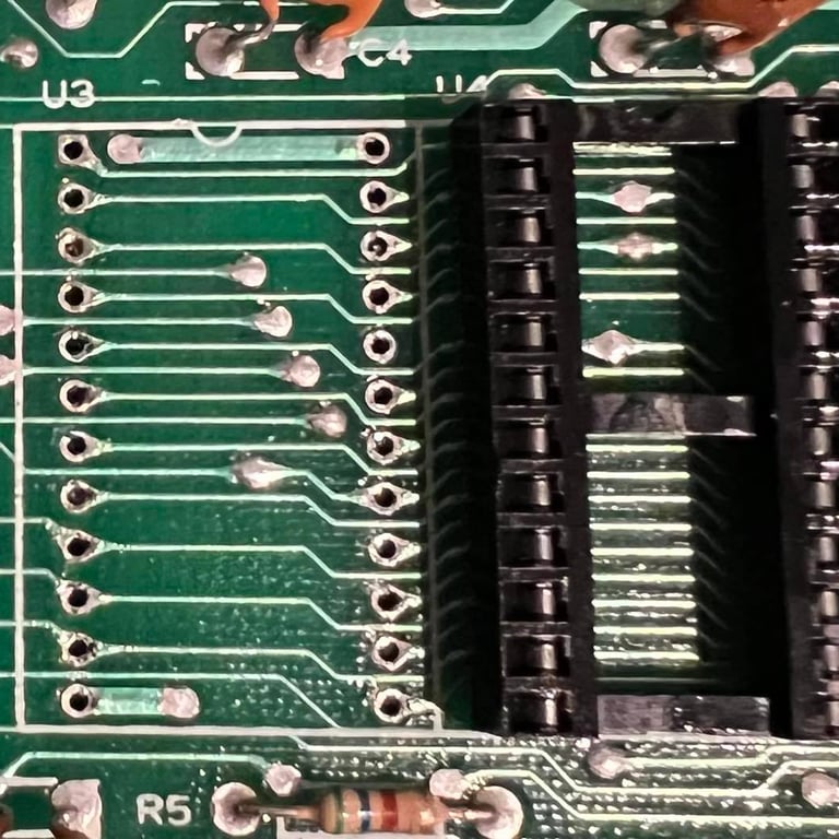
Ok, done quite some intensive testing here. Short story is that both the 6510 CPU and the BASIC ROM are ok. I do have a feeling that it´s the Kernal ROM that locks the IRQ signal. Anyway, it´s good to have the BASIC and CPU in socket anyway. The chips are desoldered without any pads or traces lifted. See pictures below (click to enlarge).
In an attempt to narrow the problem down, I remove both CPU, CIA#1, BASIC, Kernal, Char ROM and PLA. And the flickering is STILL there... My guess now is that there are something wrong with the circuitry around the VIC-II.
I start probing with oscilloscope around the voltage controlled oscillator (74LS629) and the up/down counter (74LS193). I really can´t see anything odd here while comparing these signal to a working C64 board (with same assy and artwork, but a REV B). Nevertheless, I try to replace these chips with two known working to see if the strange flickering disappear. Below you will find pictures where these two chips are desoldered. As far as I can see no traces or pads were lifted.
Now a strange thing happens. It turns out that both of these chips works fine. But when I put the old 74LS629 back in a socket, the flickering disappear? What?! I check every trace to see if I accidentally broke a trace in the operations, but connectivity are fine for all points. This is VERY weird! So now I have a black screen only - no flickering colors... Not sure if I like that better or not...
I check with the oscilloscope again around all pins on the VIC-II. And I can´t see anything obviously wrong. All clocks looks ok, there´s activity on the address/data bus and the IRQ is still stuck low. So to me it looks like the problem is still the same, but without the missing flickering colors.
So to continue my fault finding I choose to:
Desolder CIA #2 chip. This was a tip from the Commodore/Amiga Norway community.
Desolder the Character ROM. I´ve never experienced that these chips fail, but I´ve experienced that Kernal ROM fail.
Below you will find pictures of these two desoldered.

And it turns out that none of these are broken either. But it´s good to have them ruled out, and also to have sockets for these for future maintenance.
Next step is to desolder the two MT RAM chips. These are also good candidates for black screen. The only thing is that if a RAM chip fail it´s often visible by using the Dead Test Cartridge (it will flicker a number of times). And as of now the Dead Test shows nothing. Anyhow, I desolder these two (see pictures below from the desoldering).

Feels like I´m on a wild goose chase here now... But I need to keep pushing forward. As mentioned previously the MOS 7708/7711 are also known to fail. I do some checking with the oscillocope on the 7711 and I see that on pin 17 (B enable) there is a constant value of 5 V. On my working C64 this pin have a tiny pulse set to 0 V regularly. Could this be the culprit? Or could the source of this input be the culprit? The next step is to desolder the 7711 and replace with a new 74LS139 demultiplexer. Below you find a picture of the 7711 desoldered - no traces lifted.
It turns out that replacing with a new 74LS139 does not solve the problem either... Before desoldering any further I spend some time trying to use the oscilloscope to see if I can see what´s happening / what the status is in the machine. What I see is:
The IRQ still goes low->high->low. So that means that the CPU is in a constantly interrupted not being able to do anything else then trying to run the IRQ handler.
The EN1 and EN2 pin on 74LS139 does not "tick". It´s hard to see on the analog oscilloscope, but I notice a difference on these pins compared to a working C64. It is like the C64 won´t start just like an old car. See pictures below for the schematics for these two (taken from Zimmers.net).
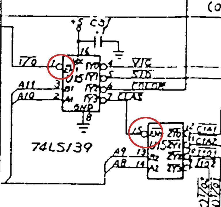
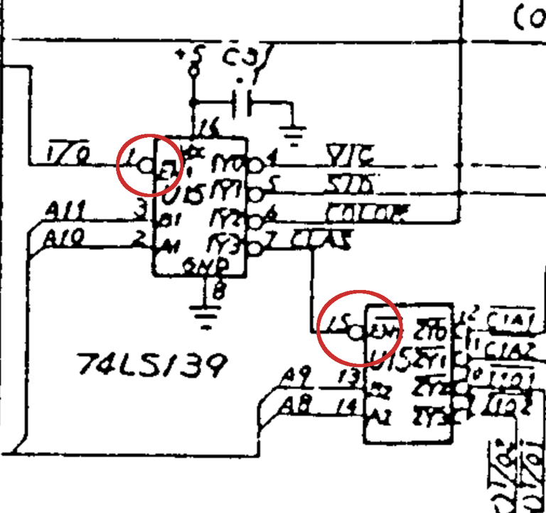
So why doesnt´t the 74LS139 tick? The EN1 input is used to enable the chips selection of input/outputs. And this output is connected to the I/O output of the PLA chip. But I do know that the PLA chip works and have sufficient power. So is it the PLA that does work - but that does not tick? The PLA is used to select the proper chip based on the input address lines A12-A15. See schematics below.
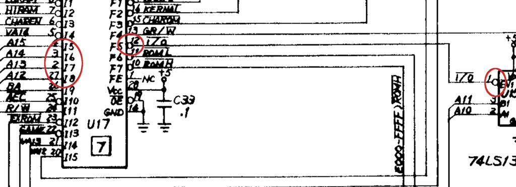

And on these four address lines i discover something that might point me in the right direction. There are activity on these four lines, but the look to be a little low on amplitude? Using the oscilloscope the maximum voltage level is approximately 3 V, and not close to 5 V as I would expect. That said, this not necessarily so that this is wrong I guess. It could be that the address traffic at the moment is just wrong. But this I will need to investigate further. See picture below for the signal on these address lines on the PLA. Does not look right?

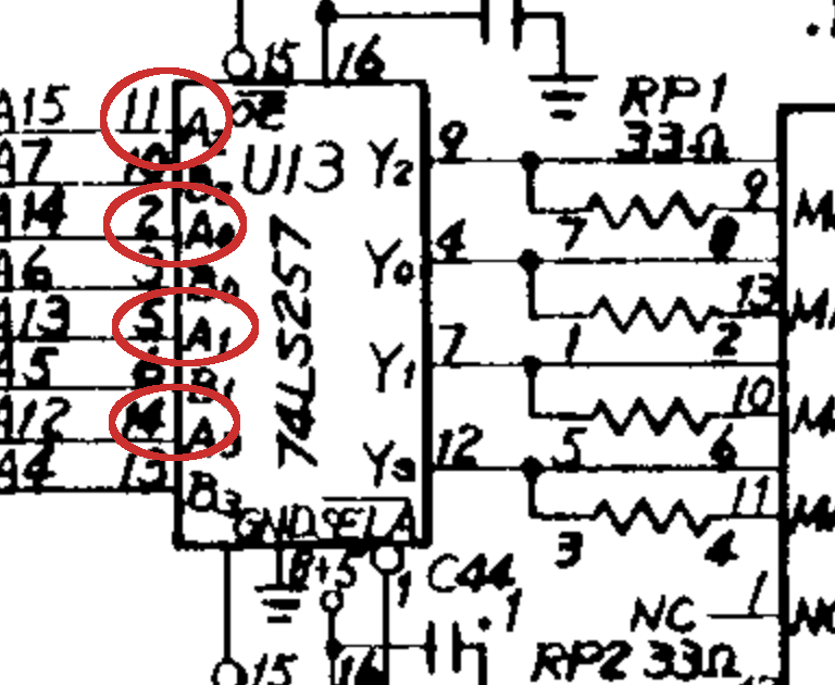
These four address lines A12-A15 are connected to both the CPU and the MOS7708 (aka 74LS257). See schematics below.

I use the oscilloscope to measure the eight address lines on the MOS 7708 on this C64, and also compare these with a known good working C64. And I get the results shown in the table below.
This could be a hint. Are the four address lines pulled down to an unrecognized voltage level? I´m not 100 % sure about this, because I do see some similarities when scoping the same address lines on a working C64. But on the working C64 these lines also have a maximum amplitude of 5 volts. So based on this I choose to desolder this MOS 7708 and replace with a 74LS257.

But... the result is still BLACK SCREEN! Oh my... this is not easy.
Ok, before I continue fault finding I make sure that the MT RAM chips are ok. I already have these two in sockets, and I test these two in a working C64. And both of the MT chips are OK also. This is starting to be a wild goose chase now - but I need to push forward.
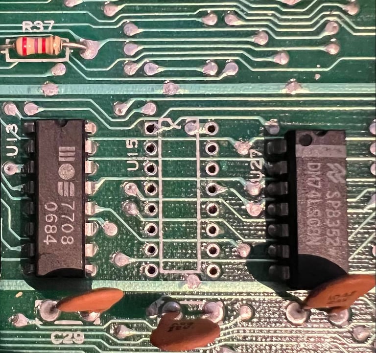
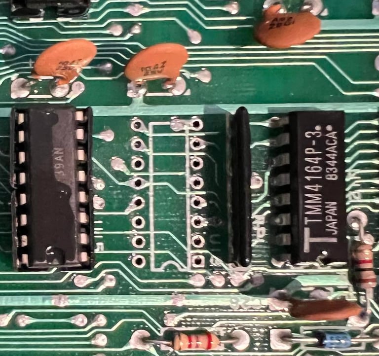
With my working C64 I remove CIA 1 & 2 and the Kernal, and I do the same with my non-working C64. This is sufficient to get the dead test to work. The working C64 starts ok with the dead test, but the non-working does not. I start probing with the oscilloscope to see if I can find any difference without the dead test cartridge installed. There are some differences on the address lines, but I think this is a result of something else. But... I now notice that there is a difference on pin 14 on the other MOS 7708. I wonder if this is the culprit? The other pins looks perfectly fine, but this single pin looks to be stuck to 5 V. These chips are prone to fail anyhow so I decide to replace it.
And LO AND BEHOLD! I think the picture below explains the result.
This was a long fault finding journey. And it was one of the prime suspect as described in the start of this fault finding. I´ve learned a lot - and perhaps the most important thing that even if a oscilloscope is very useful, it can sometimes lead you astray.
To summarize what was faulty:
A broken PLA
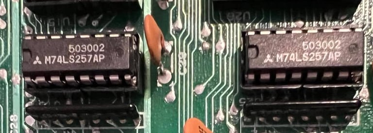
One of the two MOS 7708 was broken
I will order the following spare parts from https://www.retroleum.co.uk/:
PLAnkton replacement PLA module for breadbin C64
2 x 74LS257 to replace both the MOS 7708. This repair have shown that these can fail so better replace them with new chips from Texas Instruments
2 x 4164 C64 RAM. Even if both the MT RAM chips work in this C64 they are famous for failing so better replace these
Below you find pictures of these installed. Click to enlarge.

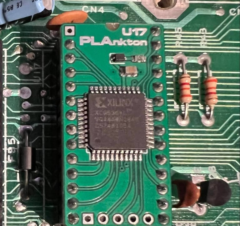


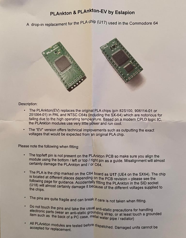
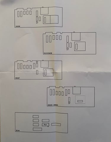
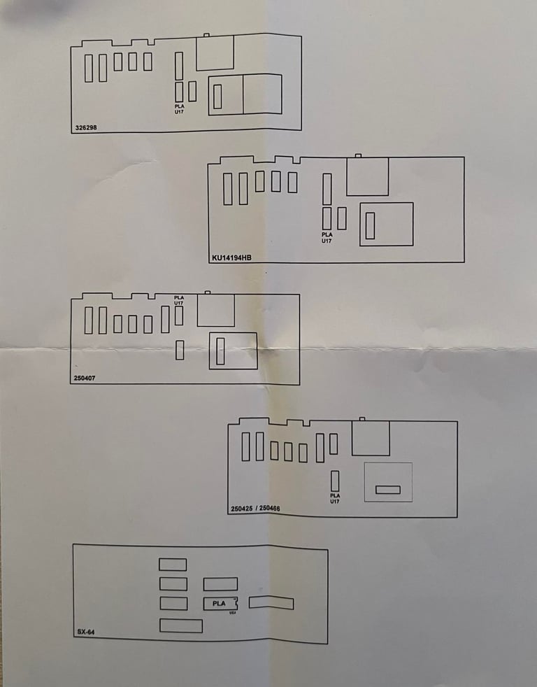
If you are interested you will find the installation manual for the "PLAnkton" chip replacement for the 906114-01 PLA chip. Click to enlarge.
Mainboard - Recap and voltage regulators
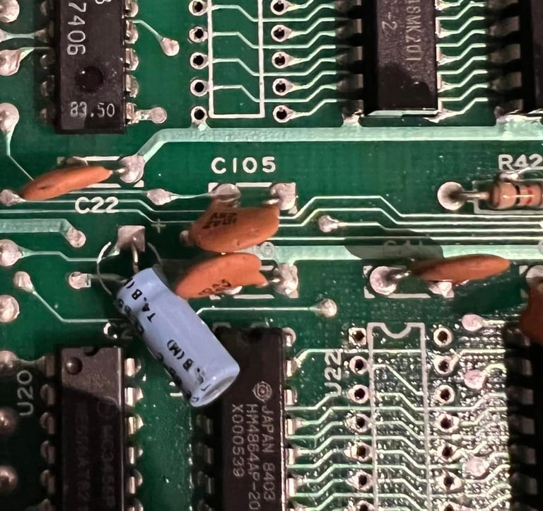
All the electrolytic capacitors are replaced with new ones. I use quality capacitors from Panasonic/Vishay, Kemet and Wurth electronics. The reason I change the electrolytic capacitors is that these can (or will) dry out due to old age. When they dry out their capacitance will change which can result in odd behavior in the Commodore 64. These faults are often intermittent and can be very hard to troubleshoot.
Below is a picture of the main board with all the new electrolytic capacitors in place. Click to enlarge.
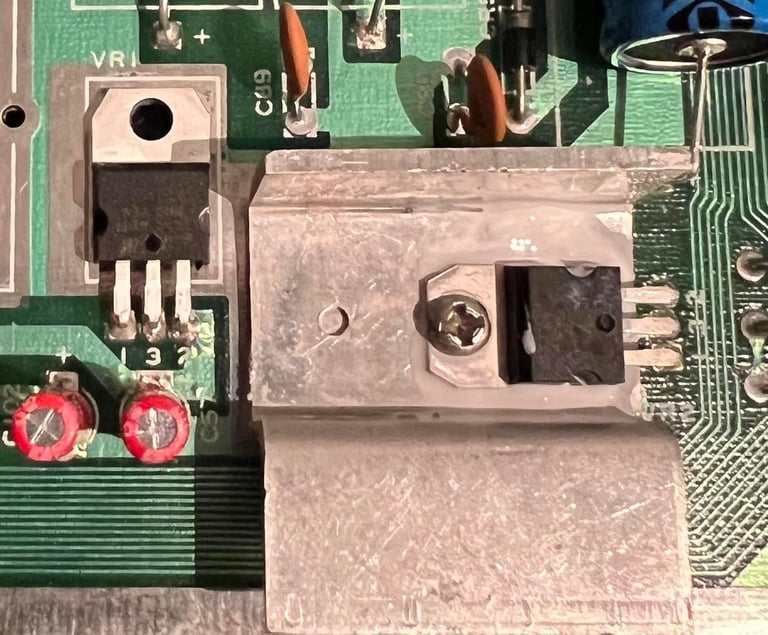
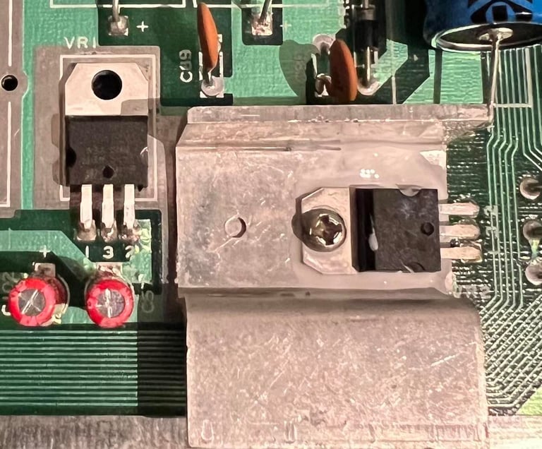
There are two voltage regulators on the board:
The 7805 5 V regulator for the VIC-II
78012 12 V regulator for the VIC-II and SID
It´s crucial that the 5 and 12 V levels are correct for these two to operate. Too low and the chip will not work, and too high the chip can be damaged. Therefore these two are replaced since the old regulators can be damaged due to age. Note that the 7085 is mounted on a heat sink with a screw, but that the 7812 is not. This is the correct way of mounting these from factory. Also, there are some cooling paste between the 7805 and heat sink.
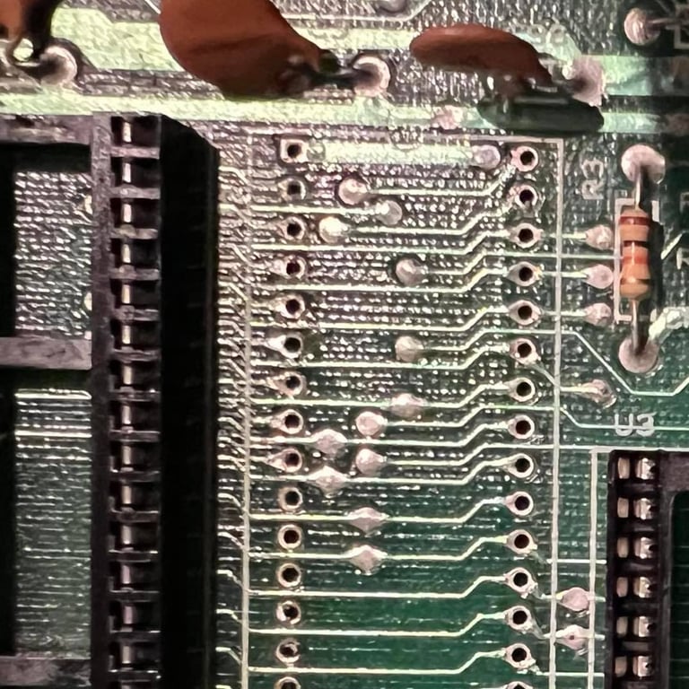
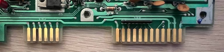
Before I move over to replacing the capacitors in the RF-modulator I give the datasette- and user port a thorough cleaning. I do this by using a combination of a rubber eraser and isopropanol. It´s important to not scrub too hard which could cause damage by removing the copper. My experience is that this is very important for the datasette to be operating properly. Below is a picture of the cleaned ports.

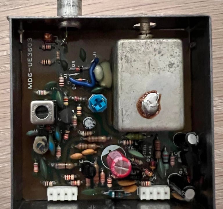
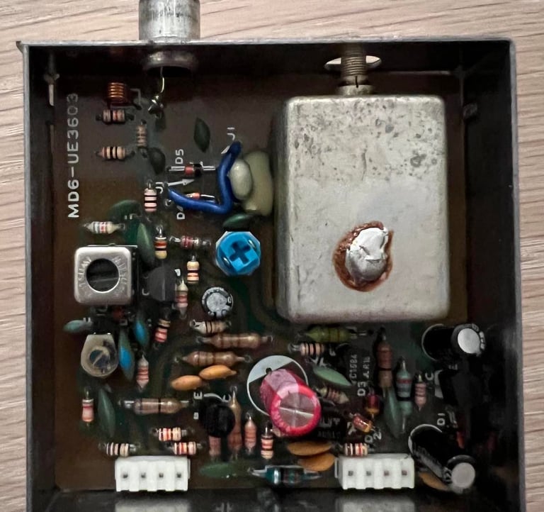
RF modulator
There are a few electrolytic capacitors also in the RF-modulator. But to replace these the whole RF-modulator case need to be removed from the main board. This can be tricky, but with some patience (and training) it can be removed. When removing the RF-modulator case patience is key; if you rush this operation you are very likely to lift some traces either inside the RF-modulator or on the main board. So keep calm and desolder on...
Before I desolder the RF-modulator case I choose to desolder and remove the remaining part of the RF shield for the VIC. I do this to make it easier to access the RF-modulator and the RF-shield for the VIC have no purpose anymore (only adding more heat). See picture below.
Here´s how I remove the RF-modulator:
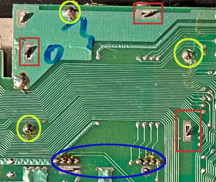
Bend the three clips to a straight angle (marked with red squares). Note that there is also a fourth clip (inside the blue circle), but this is already straight - probably never bendt in production.
Using both a soldering iron (set to about 450 degrees) and the desoldering iron I remove the solder in the three large pins (yellow circles). I hold the soldering iron on one side of the pin, and the desoldering iron on the other. When the solder is really floating I engage the vacuum to suck up the solder. Note that the fourth pin is not soldered either (inside blue circle).
Using the desoldering iron I remove the solder from the eight input/output pins (inside blue circle).

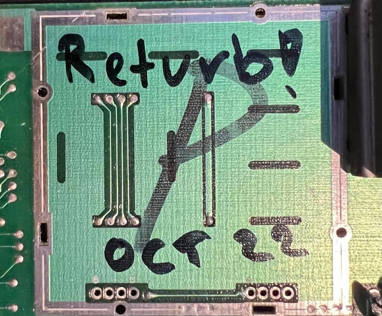
Now, with "all" the solder away I start to carefully remove the RF-modulator case. I say "all" since there is always some solder residue which prevents the RF-case from coming loose. To carefully lift it off I use the hot air gun and a small screw driver to pry the case off. This often takes quite some time since I need to be careful not to break anything. But with some patience this operation is a success - no traces lifted! Note that someone has written a "P" below the case (not me!). See picture below.

Below is a picture of the RF-modulator with the new electrolytic capacitors; all quality caps.
When the RF-modulator is soldered back in all voltages are checked and updated in the table in the "Main board" chapter. I do this to verify that everything looks fine - seen from a voltage perspective - with new capacitors and voltage regulators. And yes, all looks fine!
Heat sinks


As a preventive measure heat sinks are added to the most critical custom MOS chips: the 6581 SID, the 6569 VIC-II and the 6510 CPU. You can argue that adding heat sinks are not strictly required, but I do believe that this will decrease the probability of a chip failure of these valuable chips. Below you will find two pictures (click to enlarge). The first the complete refurbished main board without the heat sinks, and the second is with heat sinks applied.
Testing
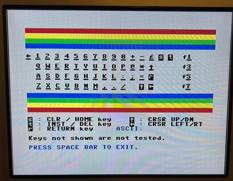
Next the keyboard is checked to verify that all keys are functioning as expected.
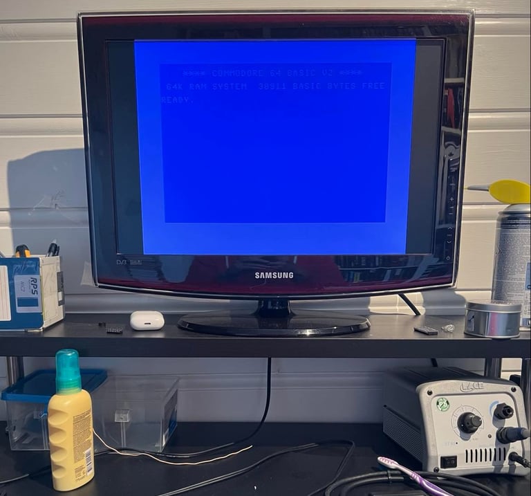
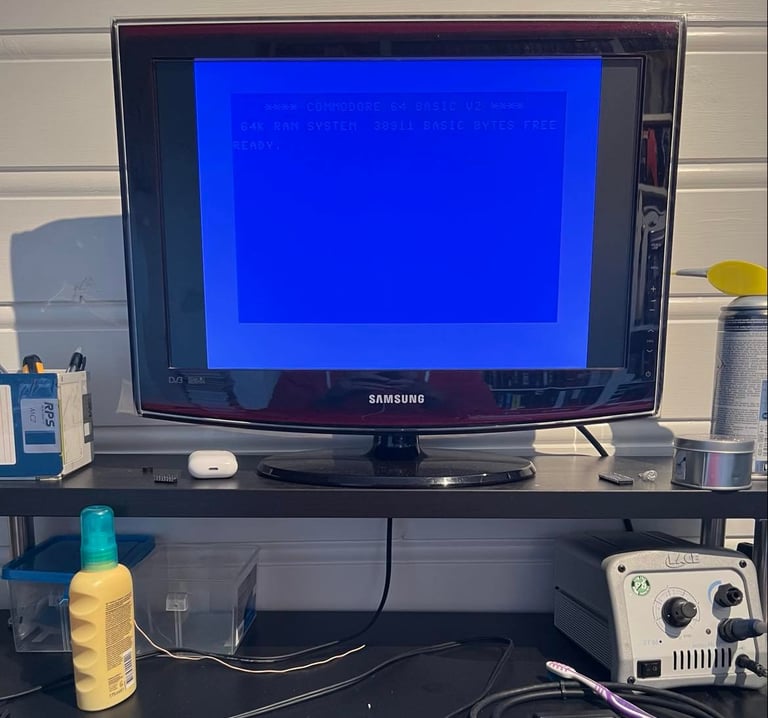
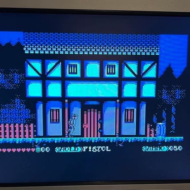
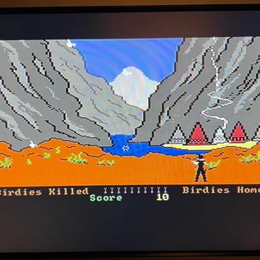
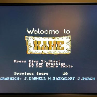
It´s time for the grand finale! It´s time to test that everything works - and let´s be honest: PLAY SOME AWESOME C64 GAMES!
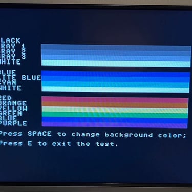
But first the machine is testet with the Dead Test cartridge. I do this just to make sure that the major chips such as the RAM, PLA, VIC, SID, CIA and CPU works. As the picture below show all works fine and pass this test without any issues.
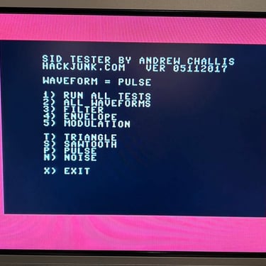
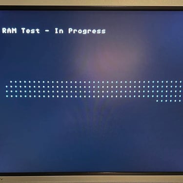
The SID is also tested. The same is RAM and video. And I can´t hear or detect anything wrong.
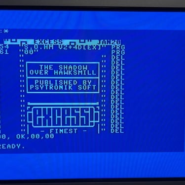
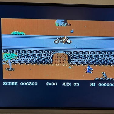
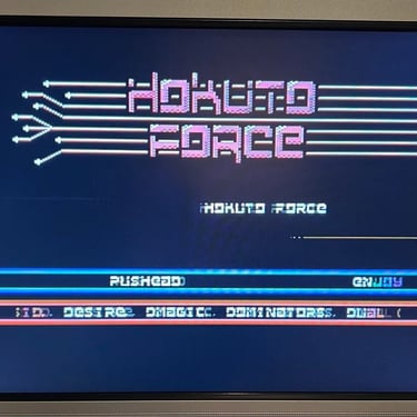
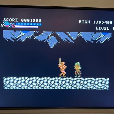
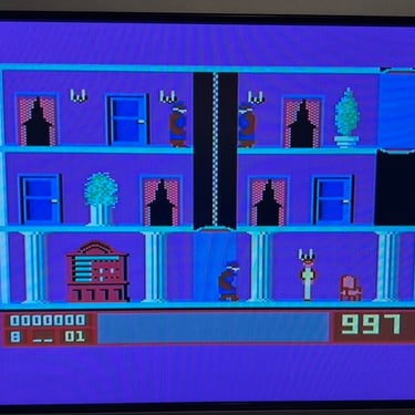
And now, with all the basics checked ok, it´s time for games and demos! I test this with Ultimate-II+ cartridge which emulates floppy and datasette very accurate. Below are some pictures from the testing. Everything works fine as far as I can see.


Final result
"A picture worth a thousand words"
Below is a collection of the final result from the refurbishment of this breadbin C64. Hope you like it! Click to enlarge!
Update
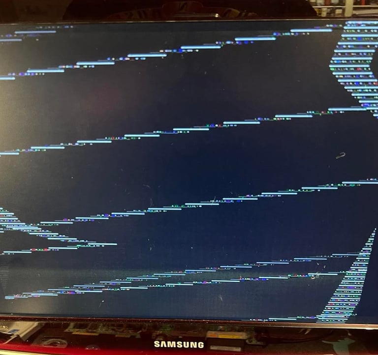
After the machine had got a new owner and home it was noticed that the graphics didn´t always look "normal". Unfortunately, I didn´t take a picture of it but when playing games such as Great Giana Sisters and Green Beret I noticed that small parts of the graphics got corrupted when the screen was scrolling. This is was not the normal bugs which are sometime common in games such as Great Giana Sisters.
A small test is done by using the VIC-II chip from C64 Ser. No. 2154273. With this VIC-II chip in place the "bug" seems to disappear. And the "old" VIC-II is then switched to C64 Ser. No. 2154273. And in this one the graphical error is not visible at all. Why? I don´t really know. It could be that some of the surrounding components in the VIC-II area (oscillators etc.) are marginally different between the machines. And that one the VIC-II chips are a bit "fragile" when it comes to exact frequence values etc.
Below is a picture of the "new" VIC-II chip installed.

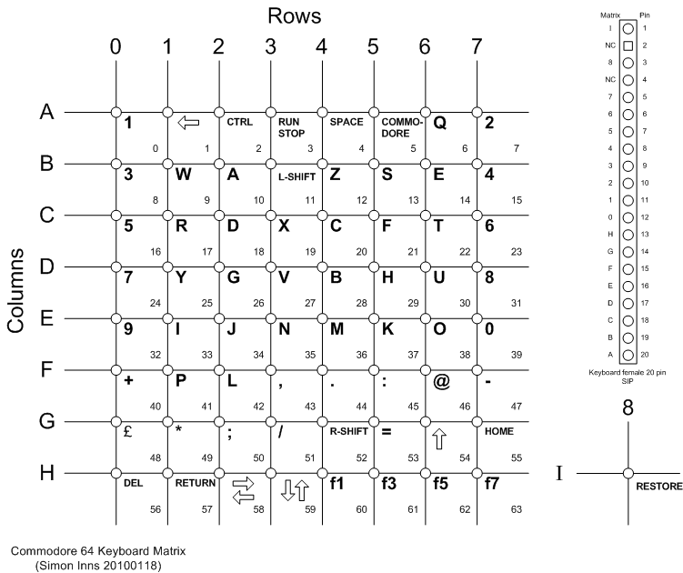
Also, during this update I notice that some of the keys doesn´t work anymore. It´s keys such as N,M,J and K. Spraying the keyboard connector with contact spray solves the problem. The problem was probably due to oxidation on PIN 16 on the connector. The schematics below shows the keyboard matrix for the C64. Notice column "E" which is on PIN 16 - here you see that the same characters which didn´t work are connected to the same column/PIN.

Banner picture credits: Evan-Amos