

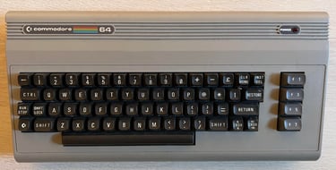
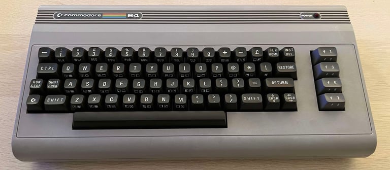
C64 Breadbin [PAL]
Ser. No. UNKNOWN
Assy 250425
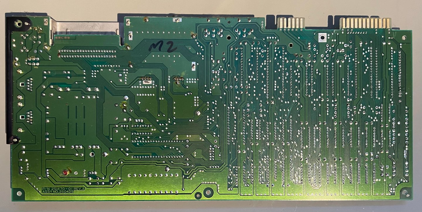
P/N 251470-01 (REV A)
Starting point
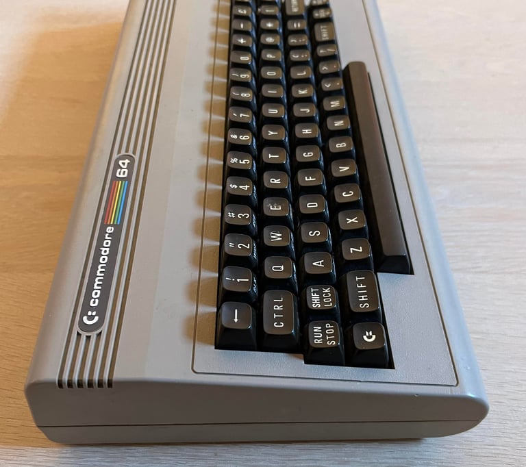
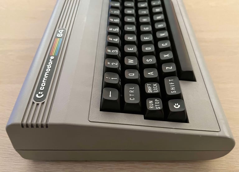
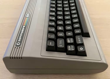
This Commodore 64 breadbin looks quite good from the outside - but it does not work unfortunately. So the machine need some repair and refurbish. It is reported to not display anything beside some very weak vertical lines.
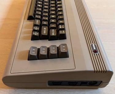
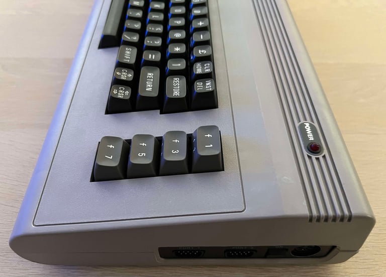
Even if it does not work the exterior is very good. There are some dust and dirt, but its very little considering the age. The only thing missing is the official serial number sticker. Instead there is another very faded sticker where you can barely ready "542407". Could this be some kind of serial number? I am not really sure.


Refurbishment plan
The refurbishment plan for this C64 breadbin (several of them in parallell):
- Refurbish the casing (cleaning, repairing and retrobrighting)
- Refurbish the keyboard (cleaning, reviving the plungers and retrobrighting)
- Refurbish main board (cleaning, checking, repairing, replacing capacitors and voltage regulators, adding heat sinks etc.)
- Recap RF-modulator
- Verify operation by testing
The plan can be updated during the refurbishment process. Sometimes I discover areas that needs special attention.
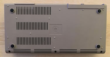
Disassembly
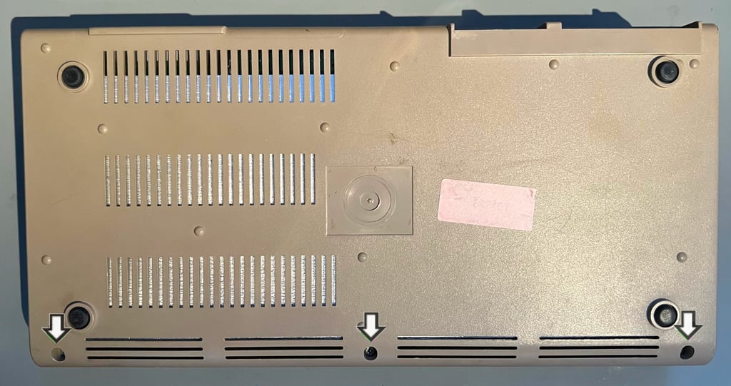
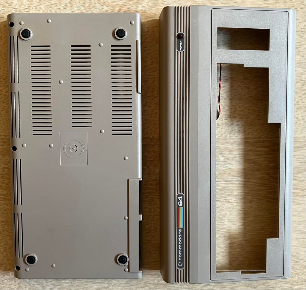
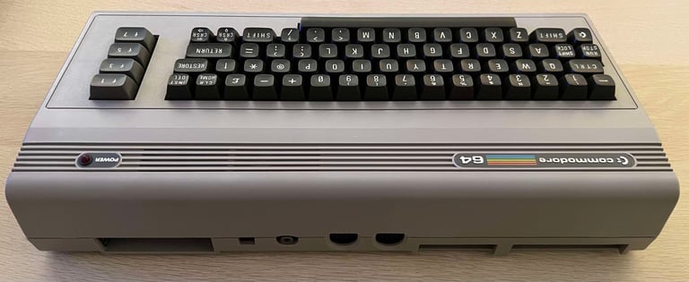
The Commodore 64 breadbin consists of a top- and bottom cover. These are held together with a few rear clips and three screws. To disassembled the Commodore 64 the three screws are removed first.

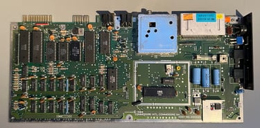
Top remove the top cover from the bottom cover it is lifted carefully about 30 degrees and then gently wiggled back and forth until it is loose. The first sight is very good. There is very little dust and grease on the cardboard RF-shield.

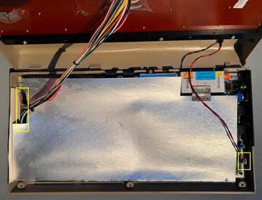
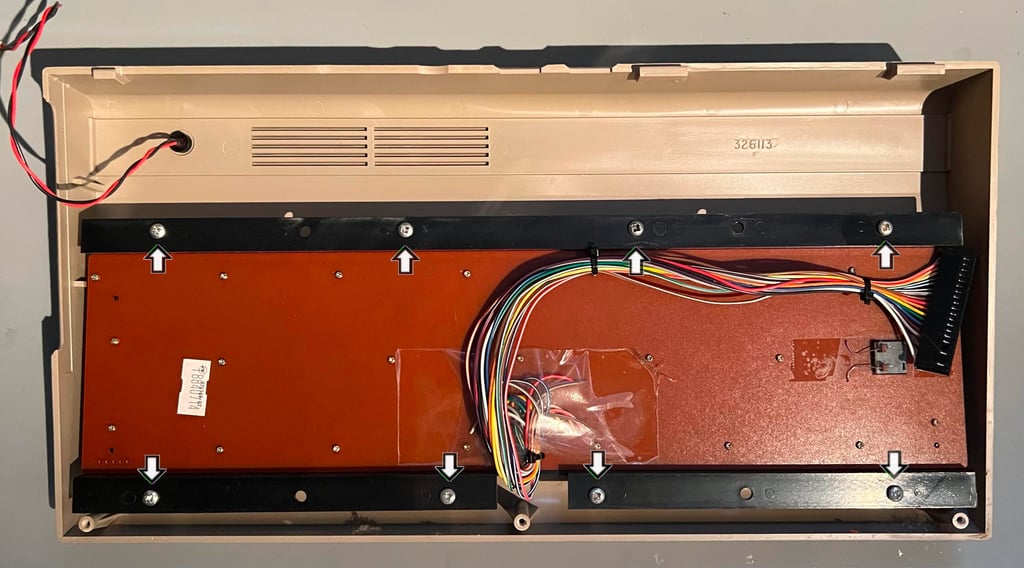
Next the keyboard and LED connector are removed (yellow squares). The cardboard RF-shield is removed and the mainboard is revealed. At first glance it looks to be in good condition. A little dust, but otherwise appear to be in good condition. I notice that several of the ICs are in sockets. This could be from factory, but I need to check later if there are sign of rework.

The PCB is attached to the bottom cover by seven screws (see above). When these are removed the PCBA can be lifted from the bottom cover.
The keyboard is mounted to the top cover by eight large screws (see picture below) which are removed. Note: the plastic standoffs holding the screws can be fragile so it is important to be very careful both when disassembling (and assembling).
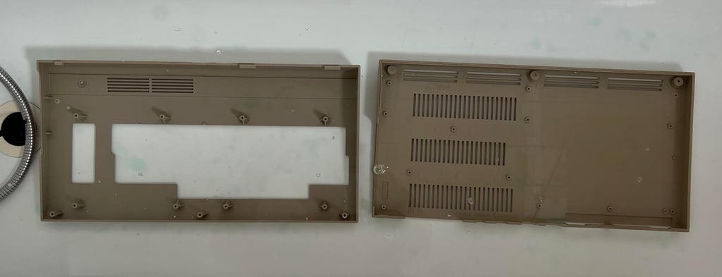
Exterior casing
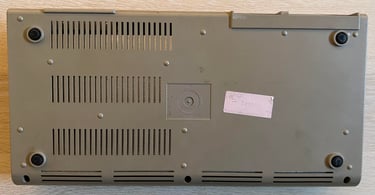
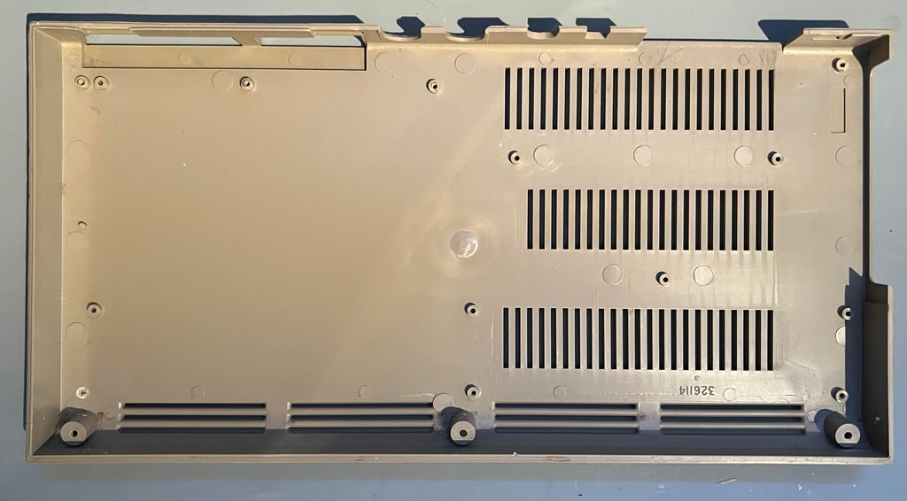
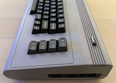
As previously mentioned the exterior casing is in good condition. There is of course some grease and dust but no severe "burn" marks or damage of any kind. The only thing to notice is that the label on the bottom cover with the serial number is missing.
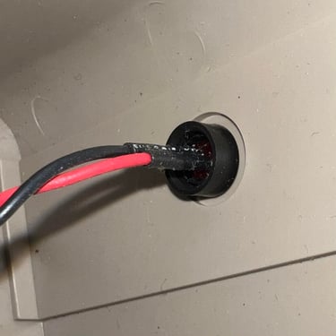
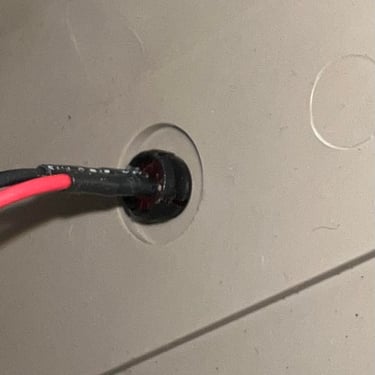
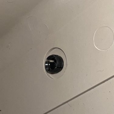
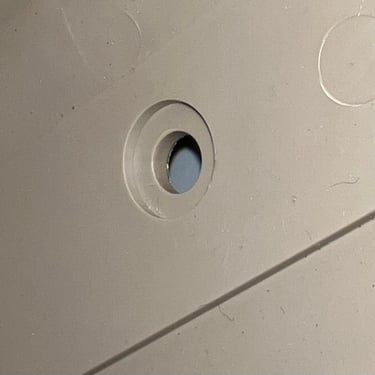
Nevertheless, both the top- and bottom cover will benefit from a good cleaning and some retrobrighting. But before this can commence the LED is carefully removed. To do this the small plastic ring surrounding the LED is removed first from the backside of the top cover. Then the LED is firmly pressed from the outside towards the inside of the cover until it pops out. Finally the inner plastic clip is squeezed out from the backside towards the frontside. Below is a small picture gallery from the process (click to enlarge).
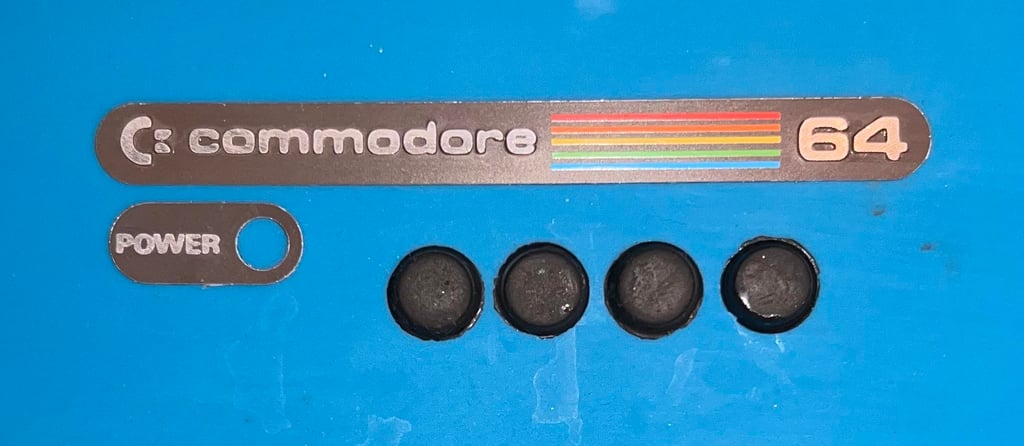
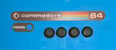
By using some hot (h)air from a hair dryer applyed to the metal badges they are carefully pried off with a scalpel. No damage is done either to the badges or the covers. Also, the four rubber feets are removed. The reason for removing these is to avoid the badges and rubber feets being damaged during the cleaning and retrobrighting process.
Both the top- and bottom cover are soaked in mild soap water for about 48 hours. This will dissolve most of the grease and fat from the covers which is crucial for a successful retrobrighting later.
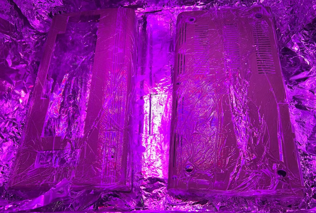
The covers are retrobrighted for about 12 hours. This is done by using 12 % hydrogen peroxide cream which is applied frequently while the covers are exposed to UV light. Also, the covers are wrapped with cling film to avoid the hydrogen peroxide cream from drying out.
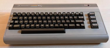
After retrobrighting and a final cleaning the result is clear: the covers looks very good! The metal badges are attached back on the covers by using some double sided tape.
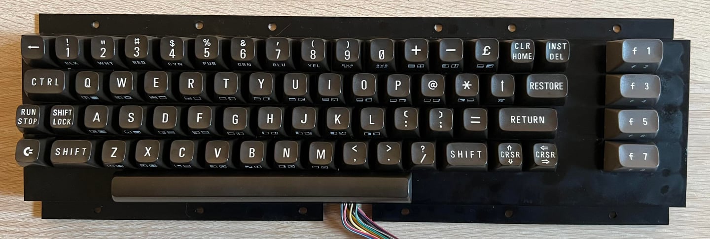
Keyboard
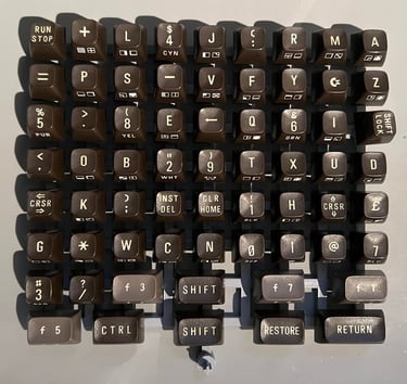
The keyboard looks to be in quite good condition. There are quite some dust and grease beneath the keycaps, but aside from that it looks very good.
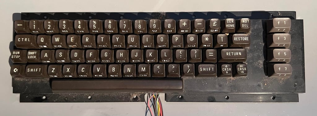
All the keycaps are removed with a special puller. Using a keycap puller will reduce the probability of damaging either plungers or the keycaps. All keycaps are removed without any damage. Note that the spring beneath the spacebar is a bit taller than the rest of the spring. So it is good practice to keep this separately from the rest to avoid mixing them up

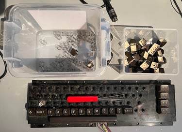
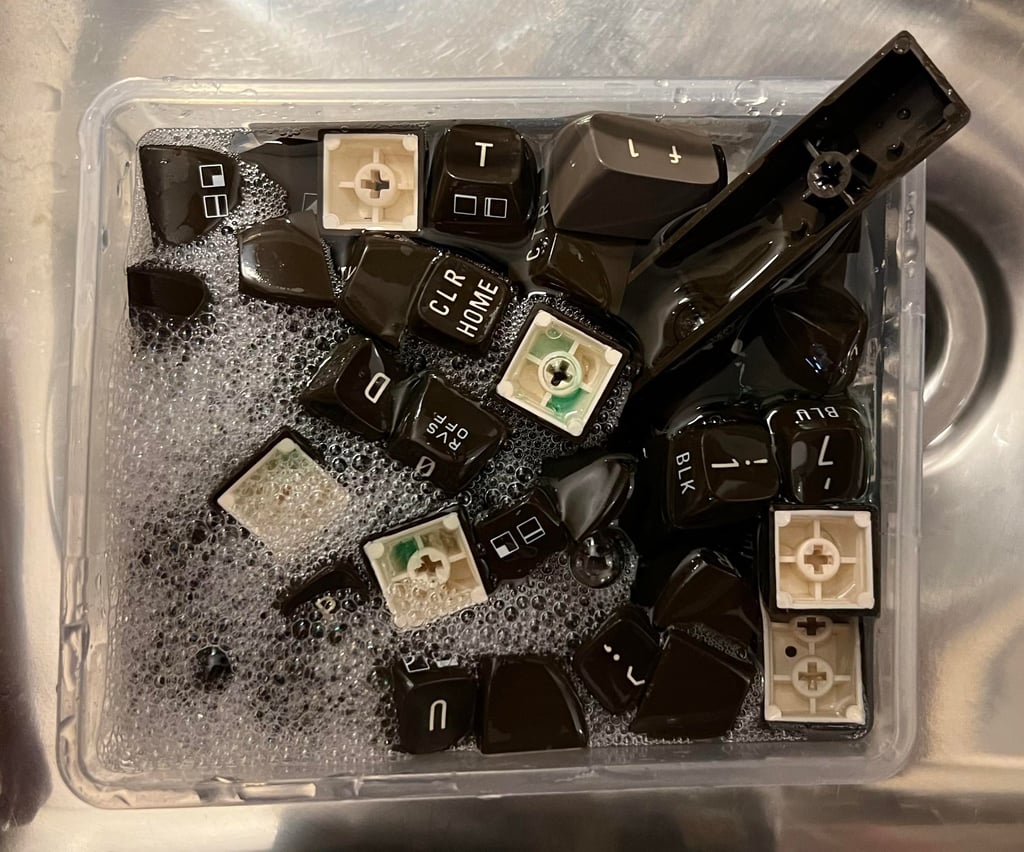
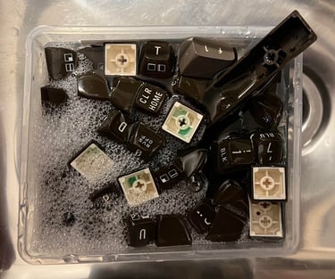
The keycaps are placed in a box filled with mild soap water for about 48 hours. This will remove most of the grease and fat which is crucial for the retrobright process to be successful later.
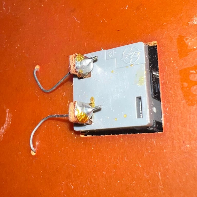
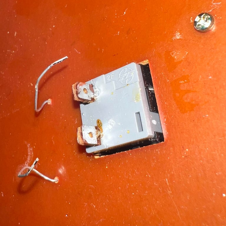
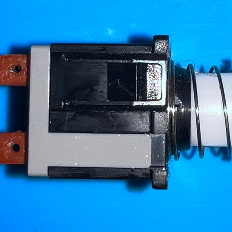
Before the SHIFT-LOCK key can be removed the two uninsulated wires are desoldered. When these are desoldered the SHIFT-LOCK key is pushed firmly from the backside of the keyboard towards the front. This will make the SHIFT-LOCK key pop out of the plastic holder. The SHIFT-LOCK key is cleaned properly with some isopropanol. See picture gallery below (click to enlarge).
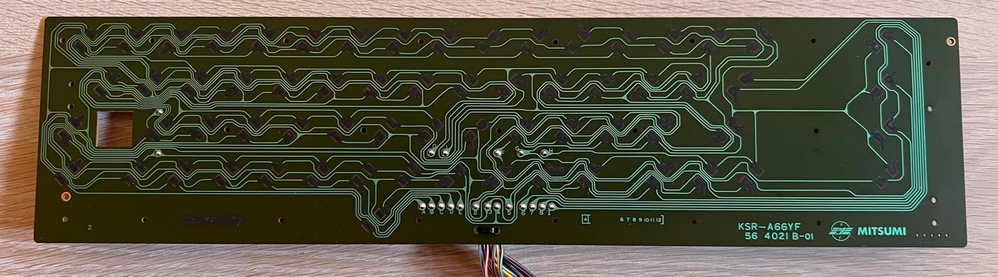
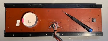
With the SHIFT-LOCK key the keyboard PCB can be removed by unscrewing all the 23 (!) small screws. The keyboard PCB is a Mitsumi KSR-A66YF 56 4021 B-01. Notice that the last "B" in the version number indicates that this PCB use carbon pads, so to clean the PCB I use only pure distilled water - no isopropanol which can damage the carbon pads. Below are some pictures of the disassembly and the cleaned keyboard PCB.
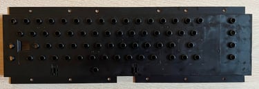
The plastic holder, for the plungers and the keyboard PCB, is cleaned properly with mild soap water. After cleaning it looks as new.
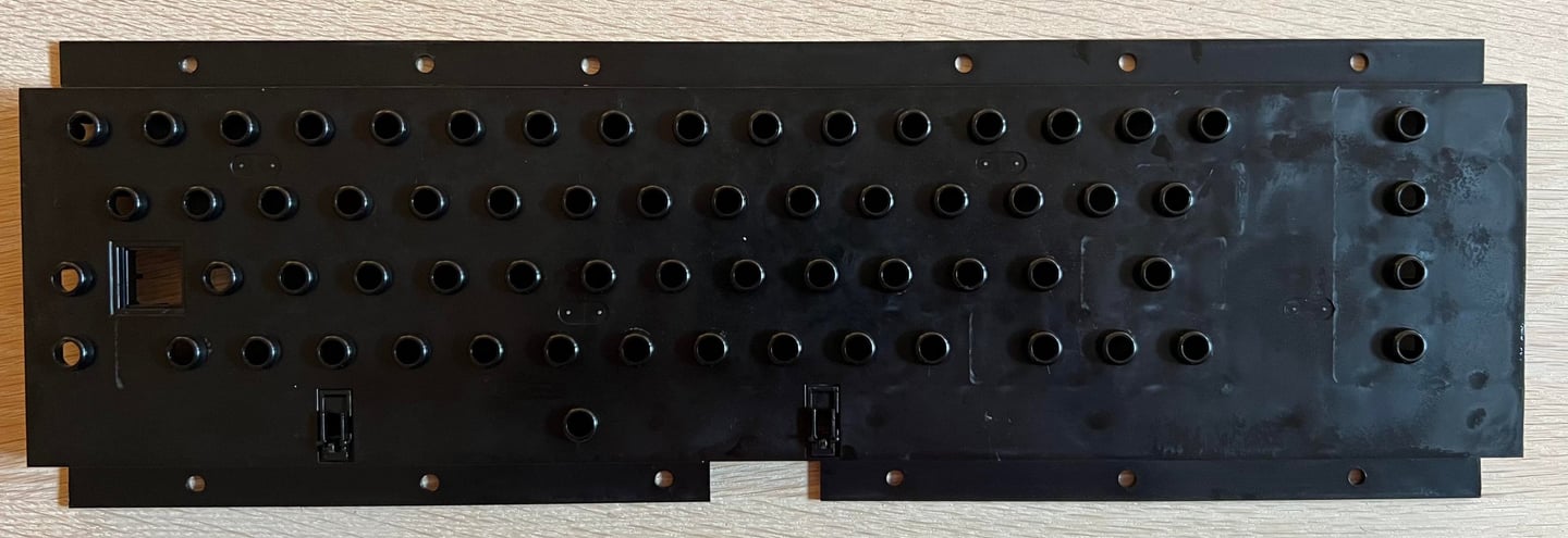
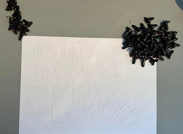
A common, well known, issue with 40 year old Commodore 64 keyboards is that the keys needs to be pushed REALLY hard to make any response. Luckily this can very often be fixed easily. The reason for this is issue is that dust and grease covers the conductive rubber at the end of the plungers. This will reduce their conductivity, so when they are pressed towards the carbon pads the resistance is too high which prevents the plungers making good contact. The easiest way to deal with the problem is to carefully rub the plungers across a clean sheet of paper. This will remove most of the dust and grease and most often bring the plungers back to their original glory.

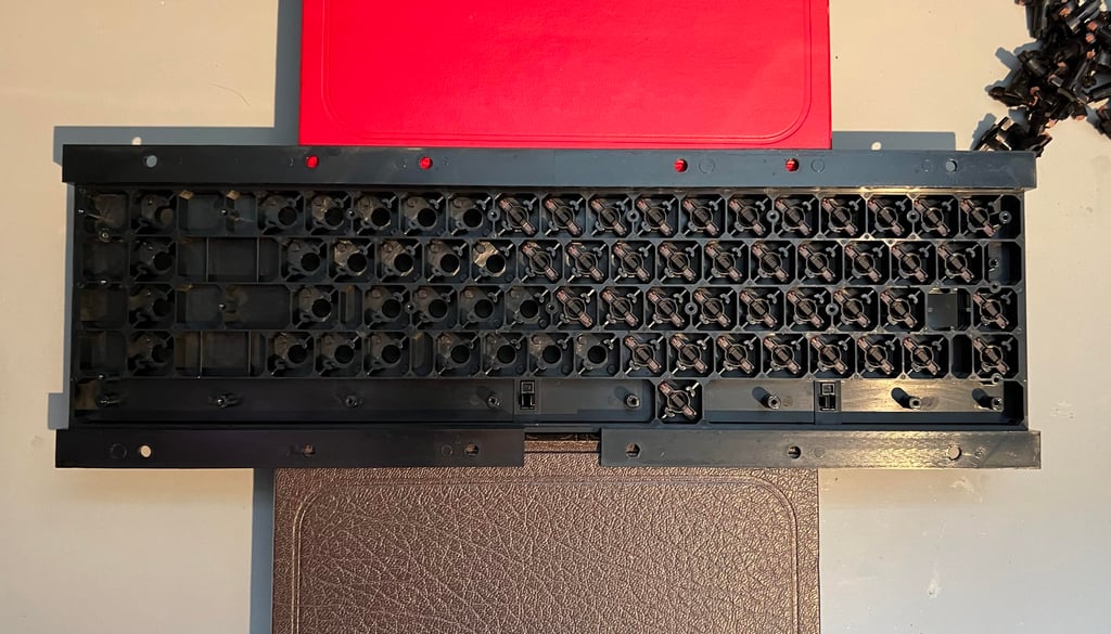
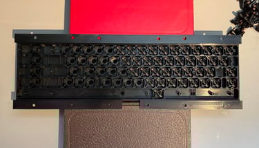
To make the re-assembly process putting all the plungers back in the plastic holder it is wise to use a few books to lift it from the table. All the plungers are put back in and the keyboard PCB is mounted.

The keycaps looks good after cleaning, but they are slightly yellowed still. All the keycaps are placed on a 3D printed keycap mount to make the retrobrighting easier.
All the keycaps are covered with 12 % hydrogen peroxide cream and exposed for UV light for approximately 12 hours. Note that hydrogen peroxide cream is added frequently (about every hour) to make sure that the cream does not dry out. Also, the keycaps are covered with some plastic cling film.

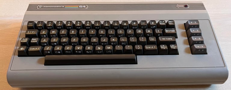
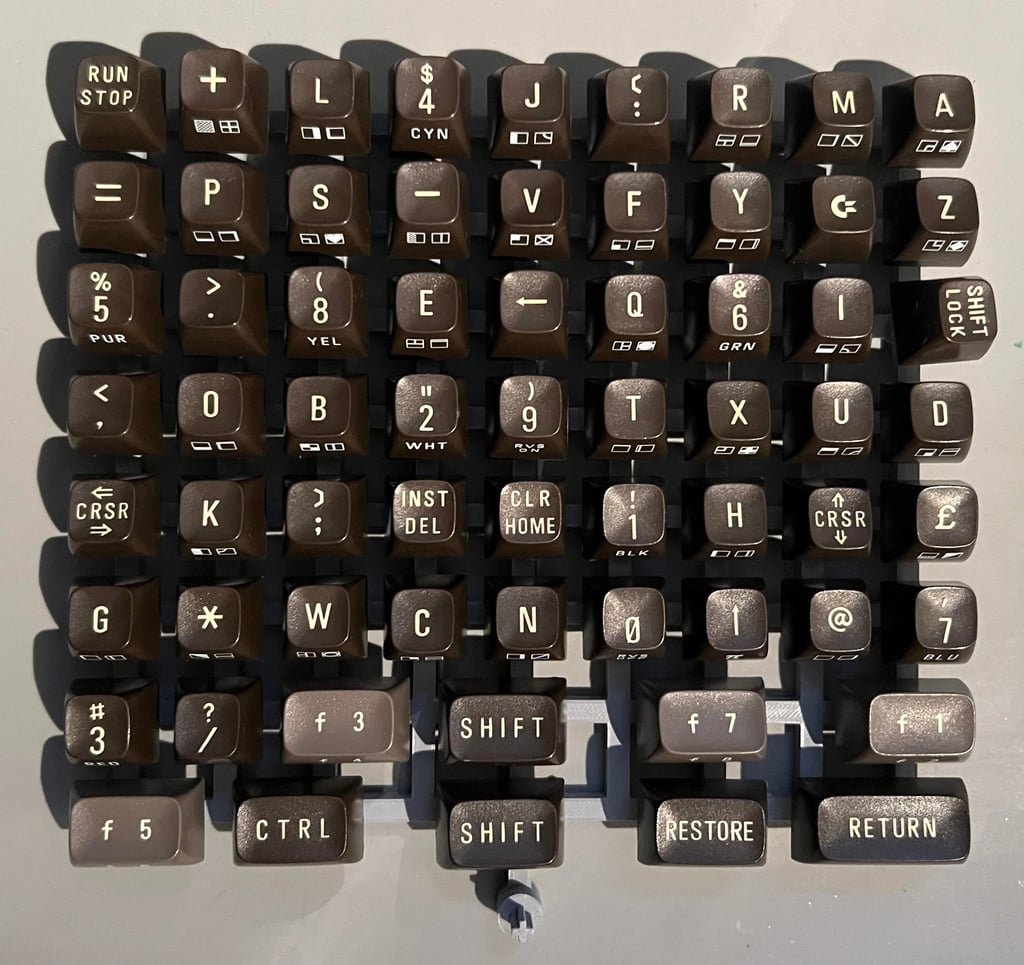
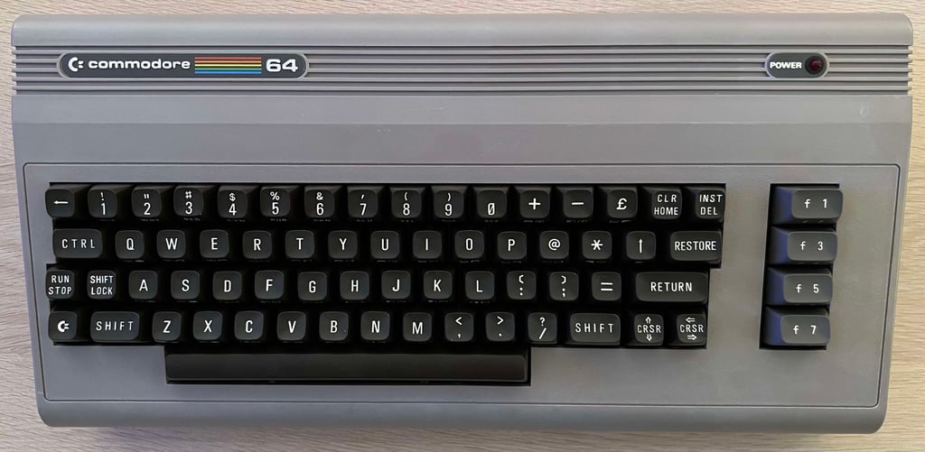
The result after retrobrighting, and re-assembly, is very good - see picture below.
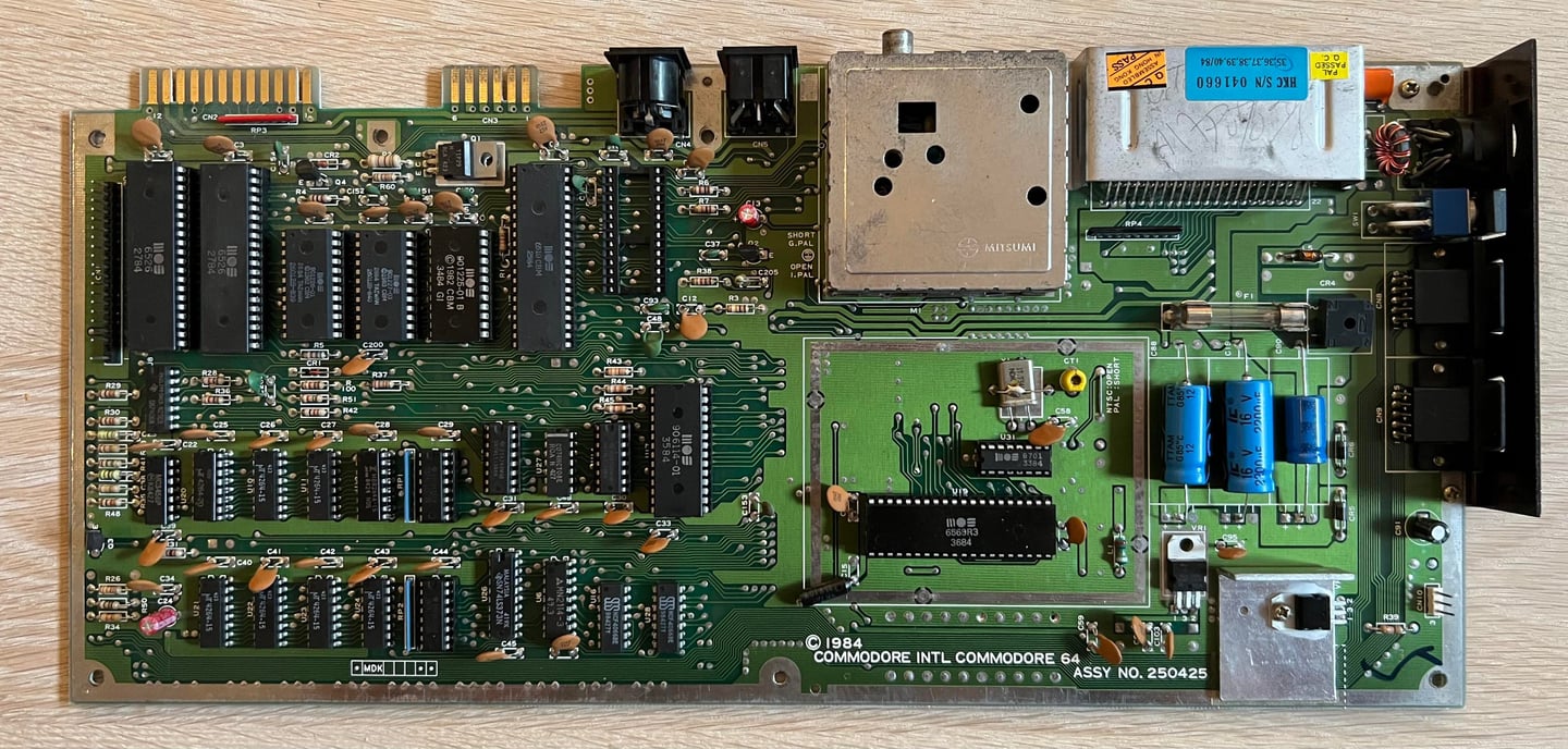
Mainboard
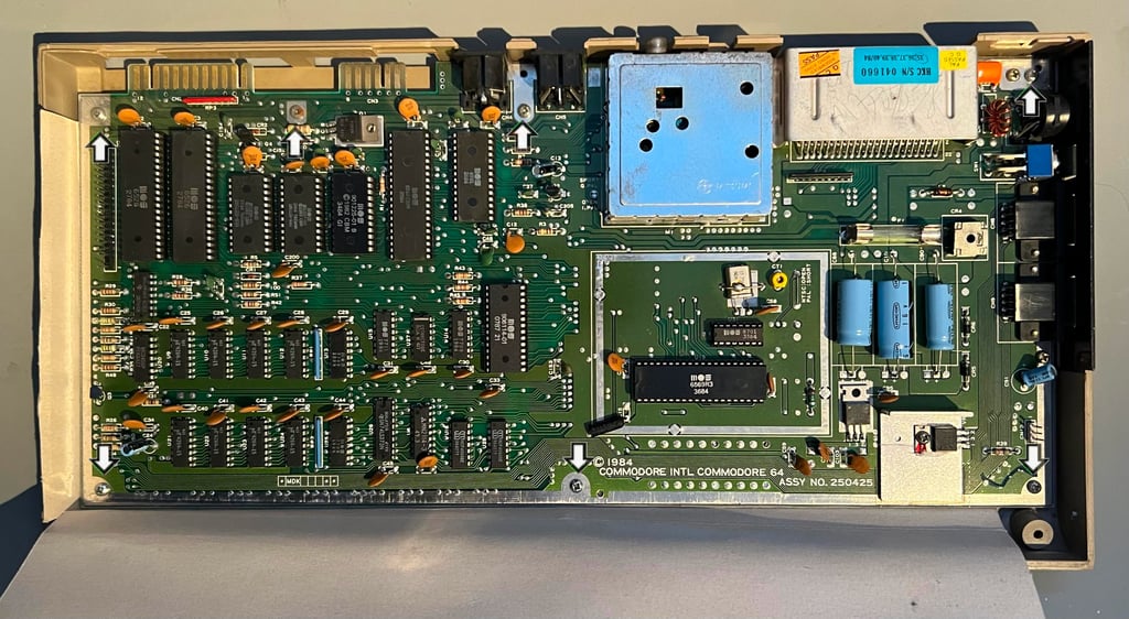
This is an Assy 2504250 / PN 251470-01 (Rev A) longboard. It is really nice to see how clean this mainboard is - almost no dust or grease. This is quite uncommon as most old Commodore 64 are very dirty after almost 40 years.
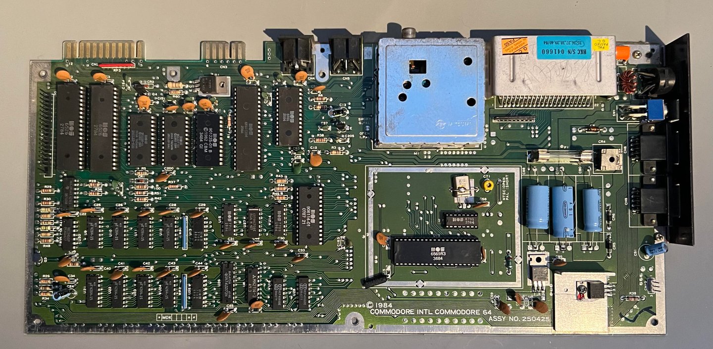

Visual inspection
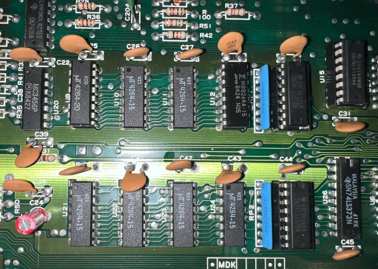
The first thing I notice is all the socketed chips - but is probably since I know that this machine is not working. But I can see absolutely no signs of rework so my assumption is that all these chips were socketed at the time of manufacturing. What I also notice are:
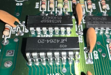
All the eight RAM chips are from Micron MT chips 4264-15. These are notorious for failing.
The MOS 906114-01 (PLA) in U17 has been replaced. The date code on this week 07 in 1987 while all of the other custom chips are from 1984.
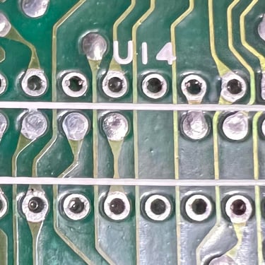
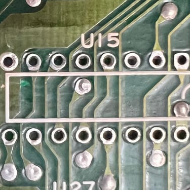
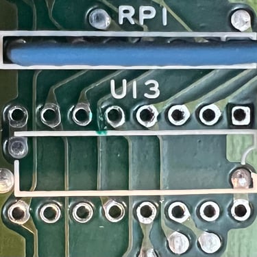
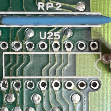
There are four MOS 77xx logic ICs: 2 x 7708 (U13,U25), 1 x 7711 (U15) and 1 x 7709 (U14). These are also notorious for failing, but can be replaced with modern TTL 74LSxx series ICs.
In the table below the custom ICs are listed. As can be seen from the table this machine was probably manufactured late summer of 1984.
Initial testing
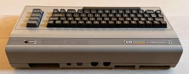
Before the machine is powered on for the first time a check for short circuit on the +5V DC and 9 V AC power rail is performed. This is easy to check at the user port – see the article of Checking the C64 voltages for the position of these. Luckily, there are no short circuit so it should be safe to power on.
Powering on the Commodore 64 results in a: BLACK SCREEN
No big surprise there as this was known in advance.
Checking the voltages
For the Commodore 64 to work flawlessly all the different voltages need to present and within acceptable tolerances. A detailed article on the subject can be found in the HOWTO - Checking the C64 voltages. In the table below all the measures voltages are listed (this list will also be updated after refurbishment). All the required voltages are present and within tolerances, so there are nothing obvious wrong in that area. NOTE: for those who follow my refurbish project you may notice that many of the voltages appear lower than seen before. I am now using a modified C128 PSU which outputs a bit lower voltages.
But the voltage on the 5 VDC at the user port is a bit too low I think. With only 4.56V this could be a problem, and needs to be investigated.
Mainboard - Repair
Hot ICs (and Dead Test Cartridge)
A good starting point for fault finding is to check for hot ICs and to run the Dead Test Cartridge. The Dead Test Cartridge is a very handy tool since it does not require all the custom ICs such as the ROMs, CIAs and SID to function. But is does require the PLA, VIC-II and CPU to boot up (and most of the glue logic). The Dead Test does not produce any signal at all unfortunately.
But after about 5-10 minutes with the power on I notice that the MOS 906114-01 PLA is getting incredible hot. Thing is that I did not notice that at first, but this IC is way hotter than normal. The PLA is notorious for failing so could this be the problem?
A known working MOS 906114-01 PLA is installed and the Commodore 64 is powered on. Moment of truth... will it work?!
Powering on the Commodore 64 results in a: BLACK SCREEN
But there is something positive! The voltage at the user port (@ 5VDC) is now up to 4.798 V. You could argue that it is a bit low, but this is probably more due to the power supply and not the machine. Also, the PLA is not getting hot now.
The PLA is tested in another working Commodore 64 and it is confirmed: the PLA was dead.
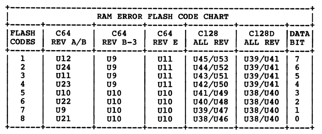
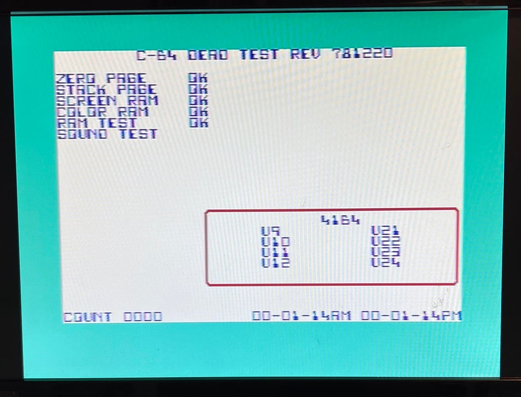
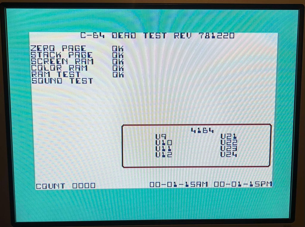
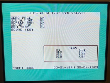
With a borrowed replacement PLA IC the Dead Test Cartridge is installed again. And this time something happens. The screen now flashes seven times. Flashing screen with the Dead Test Cartridge is pointing towards RAM issues. And this could make good sense. The mainboard contains eight MT RAM chips, and that one (or more) of these are bad is not unlikely.
According to the Dead Test Cartridge manual the seven flashes points towards the RAM chip at U9. See table below.

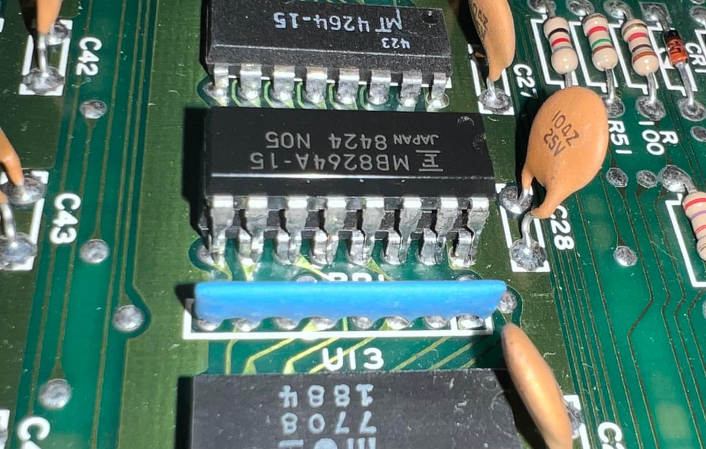
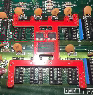
A very quick, but not always successful, method of checking bad RAM chips is "piggybacking". By placing a working RAM chip directly on top of the (potential) bad RAM chip the good chip can take over. In the picture below a known working RAM chip is placed over the U9 chip.
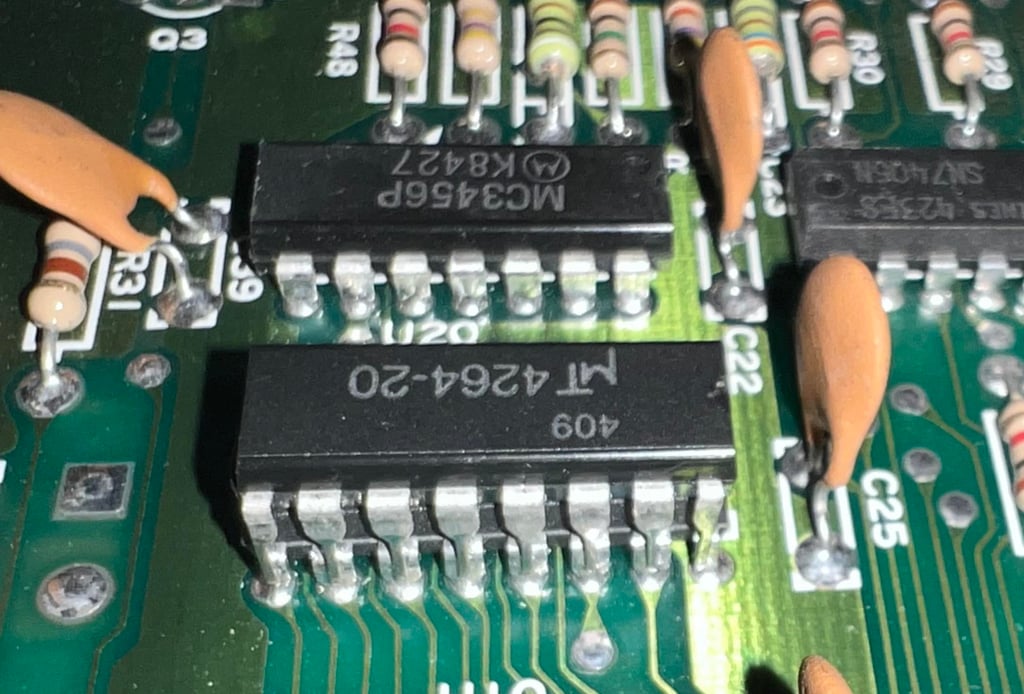
With the "new" chip piggybacked the machine is powered on again: BLACK SCREEN.
It is possible that this piggybacking method does not help. The Dead Test Cartridge is installed again, but now something else happens: one flash only! It is not always so that the Dead Test Cartridge produce correct results in this matter, but the one flash indicates a problem with RAM chip in U12. So again the piggybacking method is used with another known working RAM chip. See picture below.

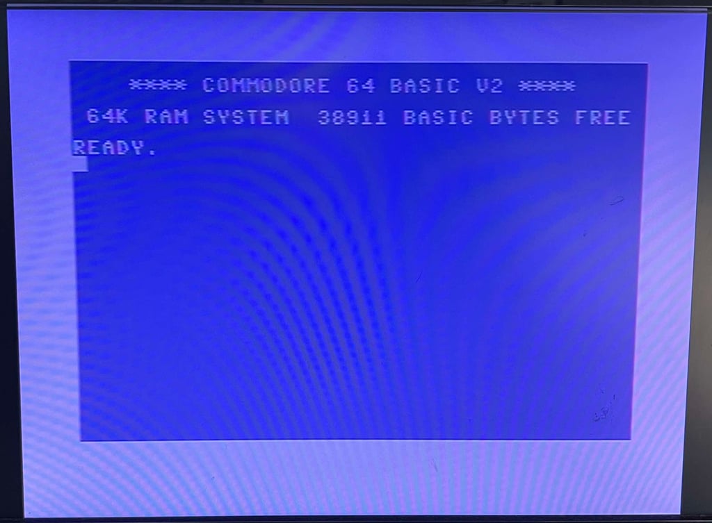
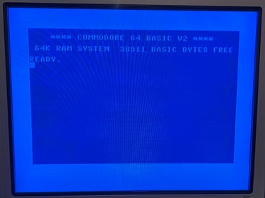
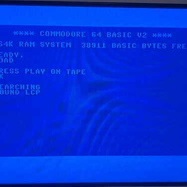
With the now two piggybacked RAM chip the machine is powered on again. This time the result is:
BLUE BASIC STARTUP SCREEN (38911 BASIC BYTES FREE)
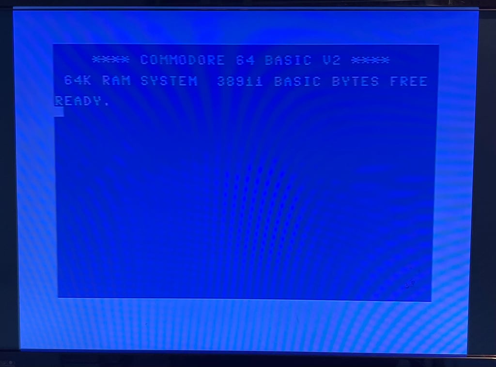
This is very good! There still can be other issues and problems with the machine, but now it is booting which is really good.
Initial test - Dead Test Cartrige
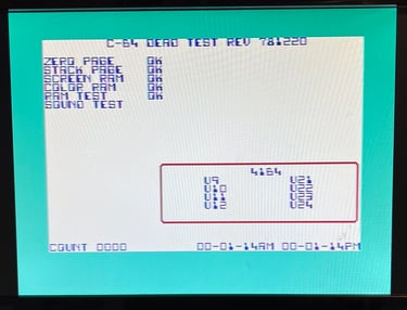
The machine is now tested quickly with the Dead Test Cartridge. This will not detect all issues, but it gives a very good starting point. As can be seen from the picture below all tests pass (and also the MOS 6569 SID chip sounds ok to me).
Mainboard - Refurbish
Replacing the 78xx voltage regulators
There are two voltage regulators on the mainboard: a 7805 and a 7812 supplying 5 VDC and 12 VDC respectively. A detailed description on how these voltages are sourced and used can be find the in HOWTO article Checking the C64 voltages. But in short these voltage regulators supply the power to the MOS 6569 VIC-II, MOS 6581 SID and the clock circuitry. The other ICs and components on the mainboard get their power directly from the power supply.
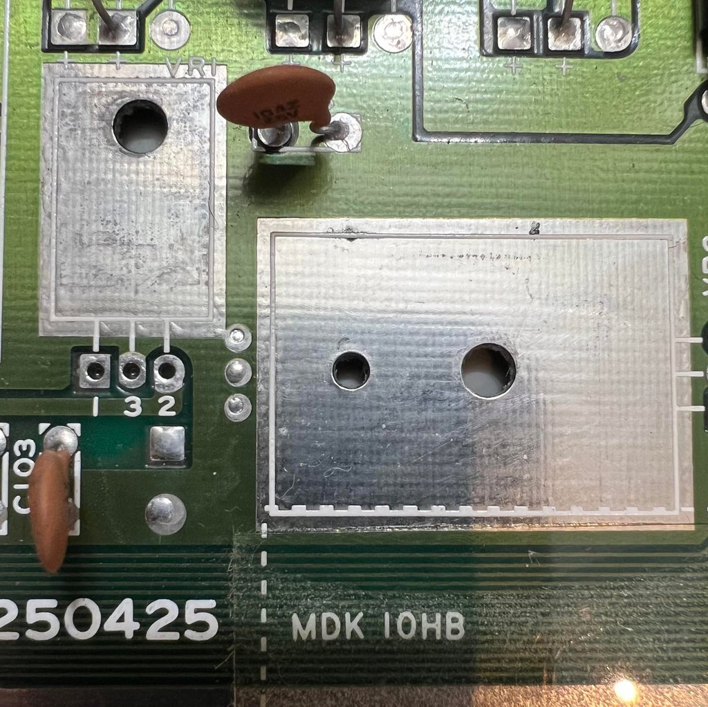
Both the 7805 and 7812 voltage regulators are desoldered without any damage to traces or pads. See picture below (the picture got cut on the right hand side unfortunately, but no pads were damaged).

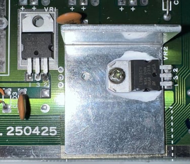
New modern 7805 and 7812 voltage regulators are installed. Note that only the 7805 (5 VDC) regulator is mounted on a heat sink (this is normal). Also, some thermal paste is put between the regulator and the heat sink for optimal heat transfer.

Replacing the MOS 77xx glue logic
Commodore was famous for making incredible custom chips such as the VIC-II and SID, but they also made their own glue logic which is another story... these are notorious for failing. Luckily, these can be replaced with modern TTL 74xx logic. There are four MOS 77xx logic ICs on the board:
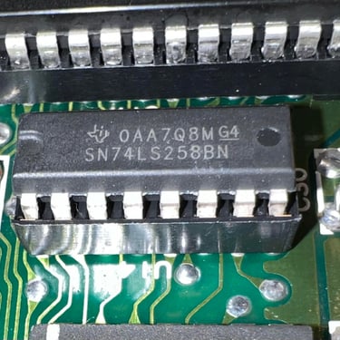
MOS 7709 (U14) equivalent with 74LS258B
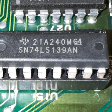
MOS 7711 (U15) equivalent with 74LS139A
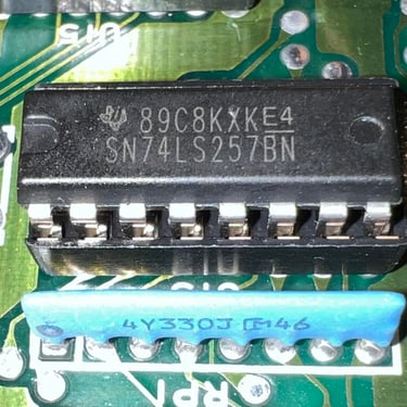
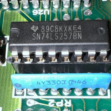
MOS 7708 (U25) equivalent with 74LS257B
MOS 7708 (U13) equivalent with 74LS257B
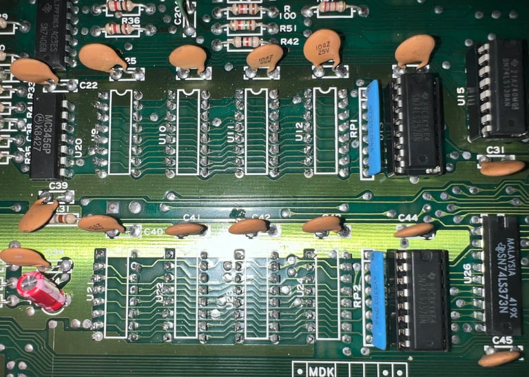
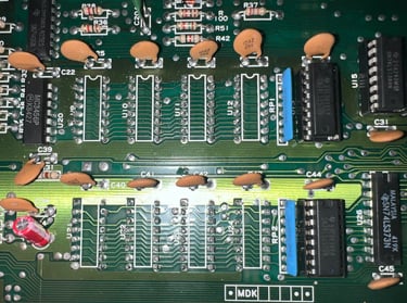
All the MOS 77xx glue logic ICs are desoldered without any damage to traces or pads. Also, a socket is installed for each of the new replacement 74xx ICs. Below is a picture gallery from the process (click to enlarge).
Replacing the electrolytic capacitors - Mainboard
The electrolytic capacitors on the mainboard are 40 years old. Even if they can still be ok it is good practice to replace these since they can have dried out. A dried out capacitor can result in a machine not working properly due to analog issues (noise, ripple etc.).
As can be seen from the capacitor list there are six electrolytic capacitors on the mainboard. All the electrolytic capacitors are desoldered without any damage to traces or pads. Below is a picture of the mainboard with the new capacitors installed.
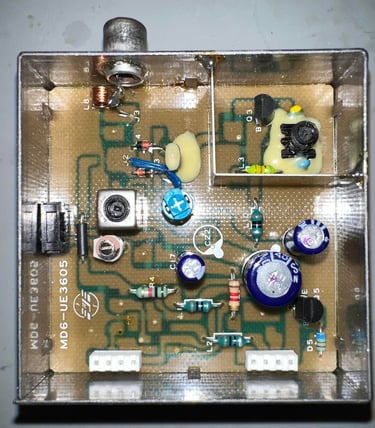
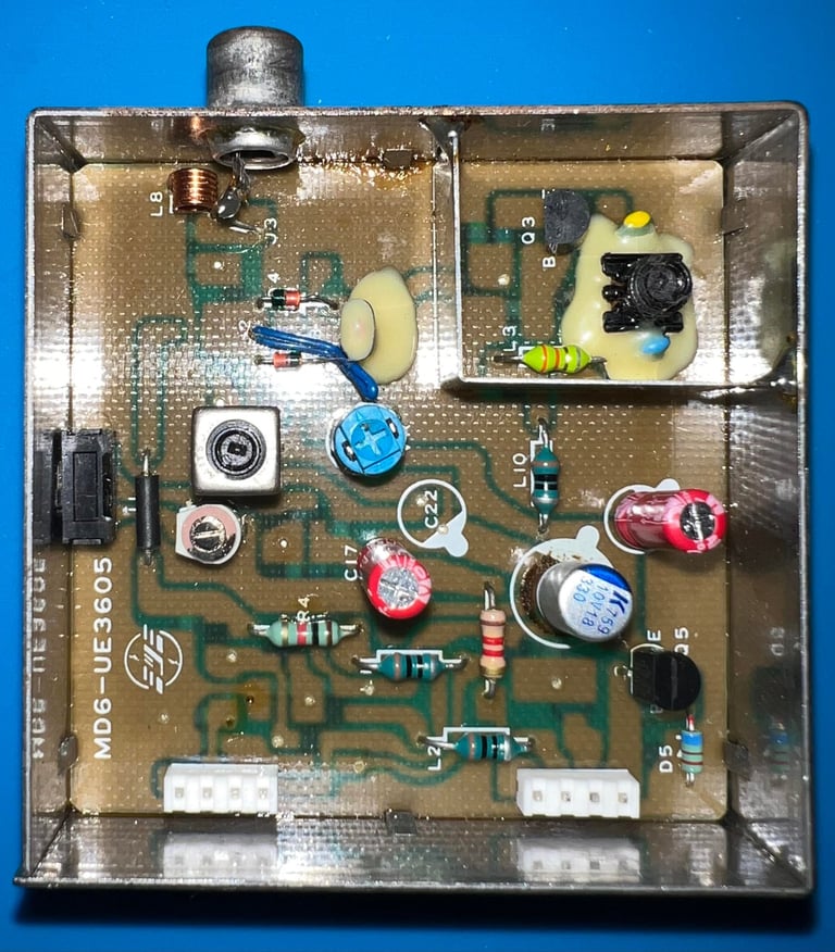
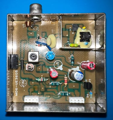
Replacing the electrolytic capacitors - RF modulator
Inside the RF-modulator (model MD6-UE3605) there are three electrolytic capacitors according to the capacitor list: 1 x 10 uF [16 V], 1 x 100 uF [10 V] and 1 x 330 uF [6.3 V/ 10 V].
Desoldering the electrolytic capacitors inside the RF-modulator are trivial, but desoldering the RF-modulator tin can from the mainboard is not. Not that it is complicated in any way, but if you do it wrong (or rush it) chances are that you will damage traces or pads on both the mainboard and the RF-modulator. On how to desolder the RF-modulator please refer to the HOWTO article Desolder the RF-modulator. When desoldering the RF-modulator on this Commodore 64 no traces or pads were lifted.

The three electrolytic capacitors are desoldered from the RF-modulator and replaced with new ones. Below are pictures from before (left/top) and after (right/bottom).

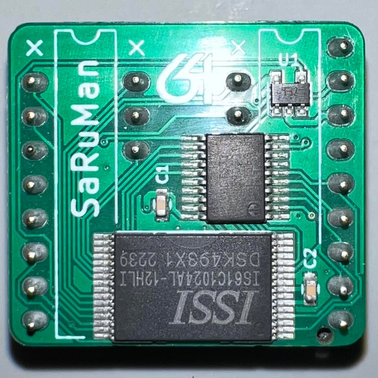
Replacing the MT RAM ICs with SaRuMan-64
The machine is equipped with eight MT RAM ICs which two are already faulty. It is very likely that several of the remaining six ICs will fail also. To try to "future proof" this machine a SaRuMan-64 SRAM replacement is ordered.
This RAM replacement is designed primarily for Commodore 64 machines with 2 x RAM chips, but can be adopted to work with older Commodore 64 revisions (such as assy 2504025) using the modification by the famous Ray Carlsen.
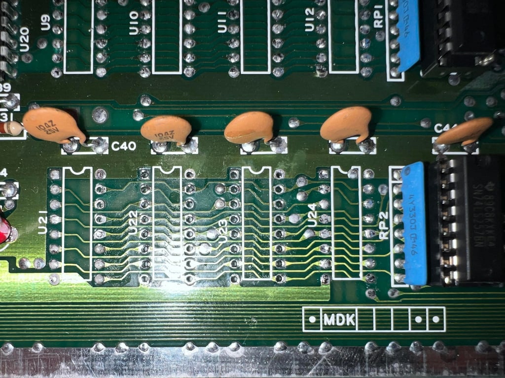
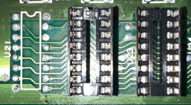
First the old MT RAMs are removed by carefully cutting the legs. Note that I do not use time to desolder each one of these. The old MT RAMs are so likely to fail that they will never be used in a refurbished machine. Below is a picture of the old MT RAMs (note that the piggyback ICs are still on in the picture) and a picture of the area with all the eight ICs cut.
The SaRuMan-64 module will be placed in to sockets in position U22 and U23. Below is a picture of the area where the solder holes are cleared - before the socket are installed.
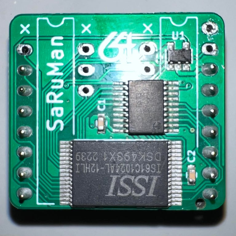
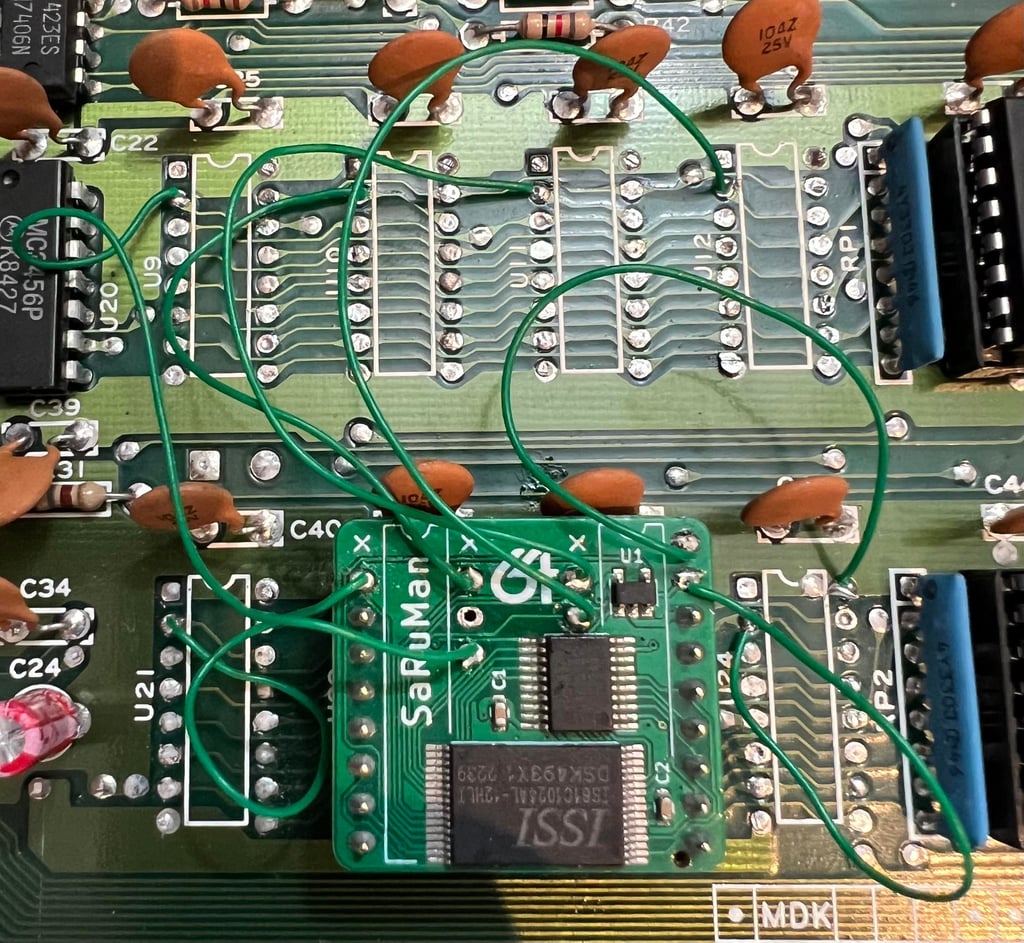
To modify the SaRuMan-64 to be used in a mainboard with eight RAM ICs some of the headers needs to be removed. This modification is described by Ray Carlsen (one of the best Commodore 64 repair men ever). Which pin headers to removed can be seen in the picture gallery below where both the original and the modified SaRuMan-64 board is shown.
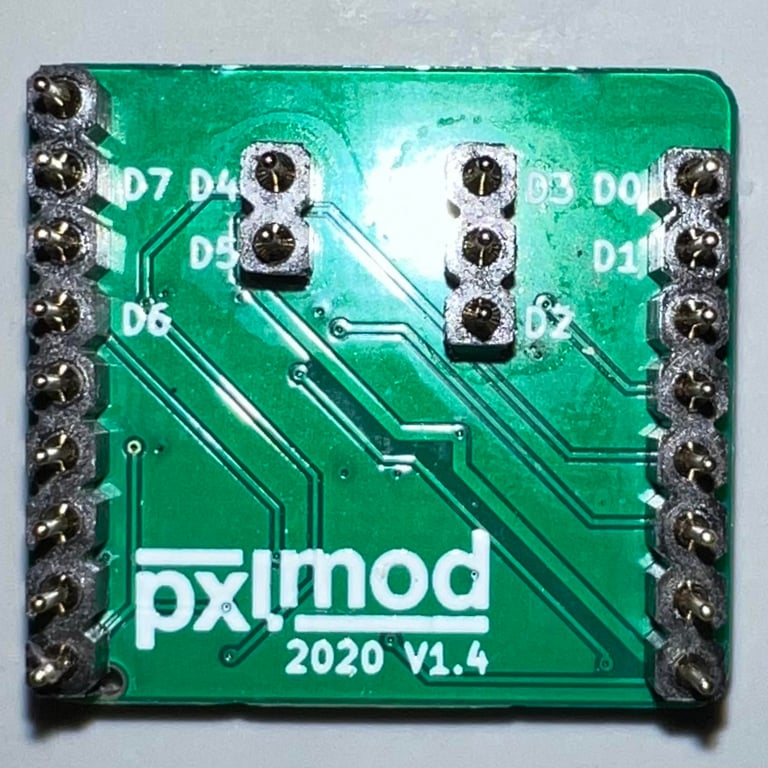
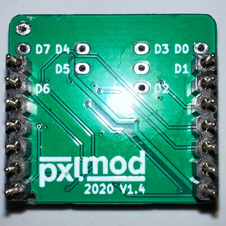
Note that when installing the SaRuMan-64 the eight data lines (D0-D7) on the SaRuMan PCB does not need to match the same data lines on the mainboard. As long as each of the data lines D0-D7 on the mainboard are mounted on a unique data line on the SaRuMan-64 it will work.


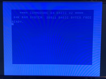
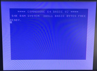
When powering on the machine with the SaRuMan64 installed trouble arise - it does not boot properly. When the blue screen appear everything is "stuck". The machine does not react to anything and the cursor is not flashing. Also, notice that there are signs of garbage on the screen which is a good indication that the data written, or read, are not correct. See picture below.
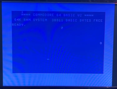
I check every connection for broken traces or short circuits, but I can not find any culprit. Also, I do not think that the SaRuMan-64 board itself is bad. It is brand new and without any damage - and modern boards and ICs are more robust than older ICs. So my hypothesis is that there is something else wrong on this machine...
After a long fault finding period
Conclusion: I do not get the SaRuMan-64 to work with this machine. It appears to be related to timing issues. Sometimes when the original MOS 7708 ICs are installed the machine boots fine, but these are prone to fail so I would not like to have it this way. New 74LS257AP and 74LS257BN are tried multiple times, but every time the machine boots with faults. In discussion with other Commodore enthusiasts at Lemon64 I try to use shorter and thicker wires - which does improve thing slightly. Sometimes it even boots to correct blue screen, but the whole thing feels "flaky". My take on this is that the SaRuMan-64 is probably compatible with this board, but to get it to really work properly the wires need to be "perfect" and probably using the old MOS7707 ICs (?). So I will save this SaRuMan-64 replacement for later.
A new attempt - Introducing the 250425 SRAM module from CBRetro.fi
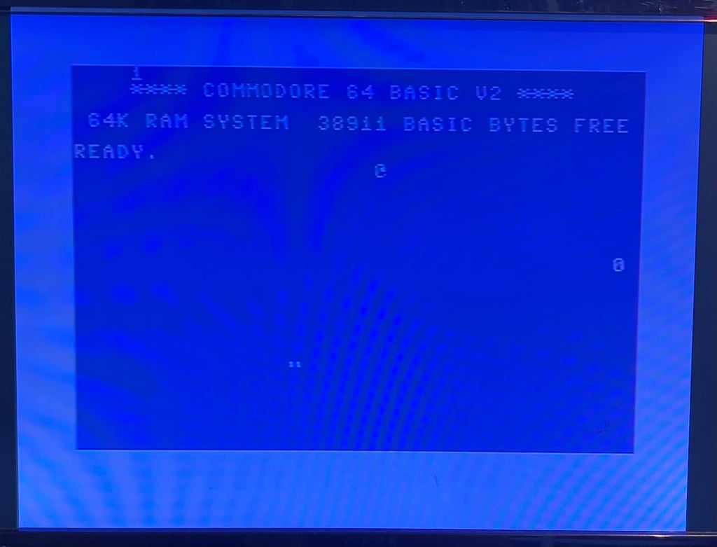
What I did learn from the SaRuMan-64 is that the Commodore 64 is depending on precise timing. And even if the SaRuMan-64 does work, in itself, the wires connecting it to the board are not really possible to get perfect in length/thickness. So, instead I order a SRAM module from CBMRetro in Finland. This module and PCB is designed to fit in 250425 motherboard. Below is a picture of the installed SRAM module.

With the new SRAM module installed the machine is powered on again. This time the result is:
BLUE BASIC STARTUP SCREEN (38911 BASIC BYTES FREE)
Replacing the PLA
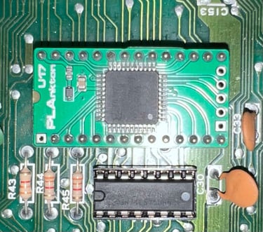
During the repair so far the faulty PLA has been replaced with a known working PLA from another machine. But a modern replacement is ordered from Retroleum - The Retro Spares Shop: the PLAnkton designed by Eslapion.
The PLAnkton is installed in the U17 socket. And as expected the machine boots to blue startup screen without any issues.

Replacing the crystal oscillator and clock generator
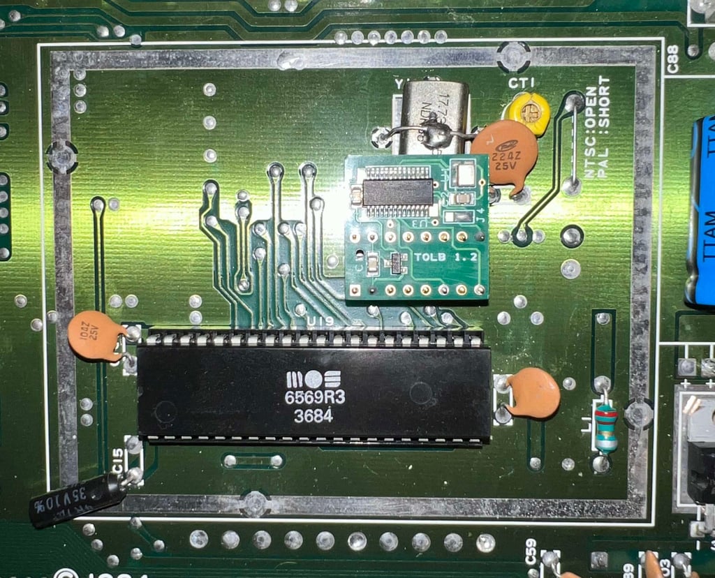
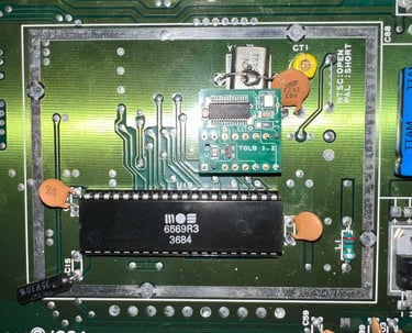
Eh? What? Well, in order to try to investigate a fault on another C64C the crystal oscillator, and the clock generator MOS 8701, is borrowed from this machine. And in return a brand new TOLB module (designed by Eslapion / sourced from Retroleum) is installed. This is a modern replacement for both the clock generating IC (the MOS 8701) and the crystal oscillator. Nice! Note that the old (now unused) crystal oscillator is faulty. But it is still in place for the looks of it.
In the picture below the newly installed replacement is shown.
Adding heatsinks to custom ICs
As an attempt to reduce the risk that custom MOS ICs become faulty due to heat heatsinks are added. The ICs which becomes the warmest are the CPU- SID- and VIC chip.
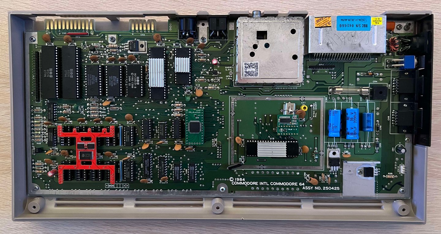
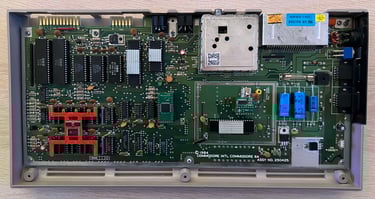
Below is a picture of the refurbished mainboard with the heatsinks mounted.
Testing
Proof is in the pudding - does it work?
Testing is done through two main stages:
Testing the basic functionality and chips
Testing by using the machine playing demos, games etc. accessed by both floppy and datasette to verify correct operation
Basic functionality and chips
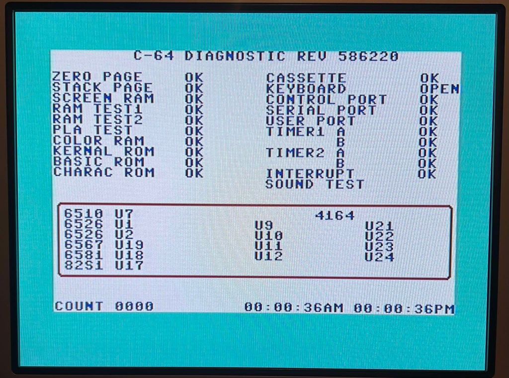
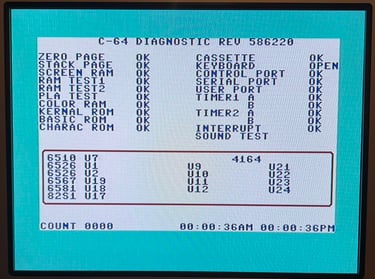
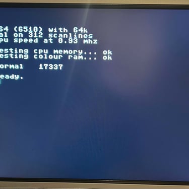
First test is done using the Dead Test Cartridge. This test doesn´t test all the functionality of the Commodore 64, but it does test the basic functionality of the major chips such as the CIA #1/2, CPU, VIC-II, PLA, RAM and SID. As the picture shows below the test is passed.
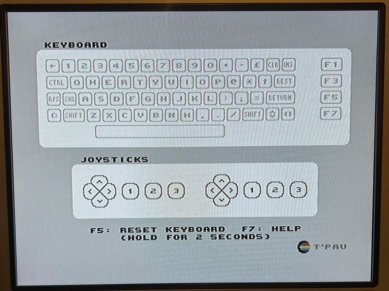
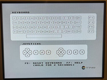
Next test is to power the Commodore 64 to the blue boot up screen and also check the keyboard to make sure all keys works as they should. The test is passed; all keys works and 38911 BASIC Bytes Free.

The Diagnostic Cartridge, and the test harness, is connected to perform a more thorough testing. The result is that all tests pass without any issues or problems.
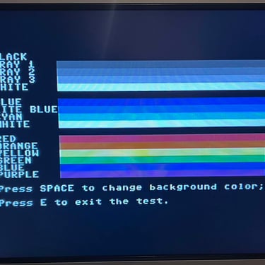
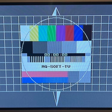
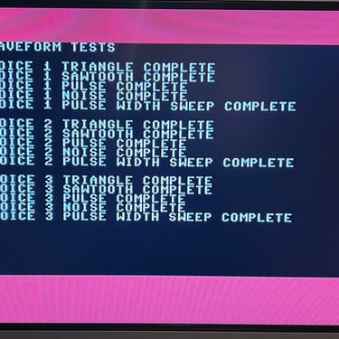
The basic functions of the VIC-II, SID and RAM is tested with 64 Doctor, Commodore 64 SID tester and MemTest64. Note that this is to be considered as basic functionality - more advanced (?) functionality such as sprite handling / collision detection / advanced audio will be tested later. But the basic tests pass without any detected faults (click to enlarge).
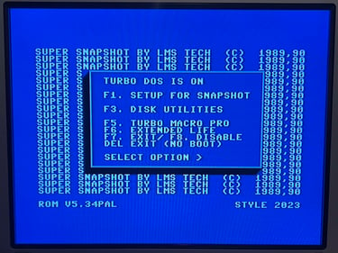
Last basic check before moving to more extensive testing is checking the cartridge. This is done by using the Super Snaphot V. Result is that the test is passed.

Extended testing
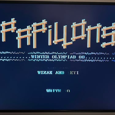
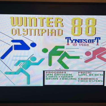
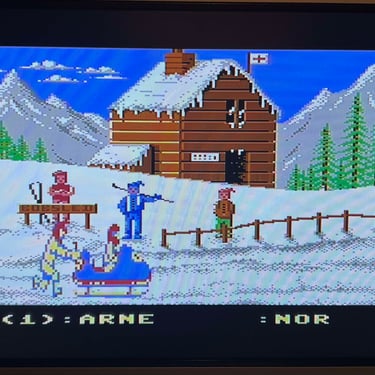
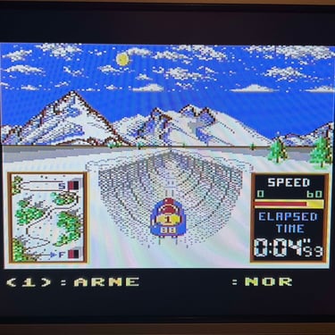
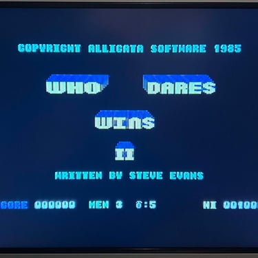
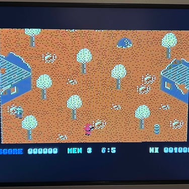
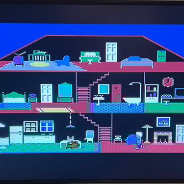
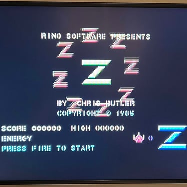
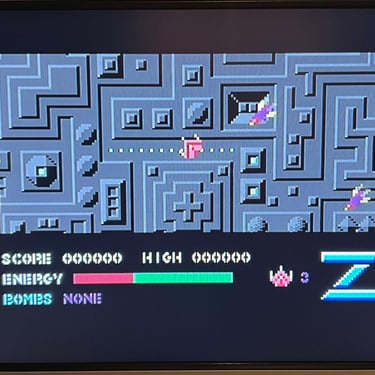
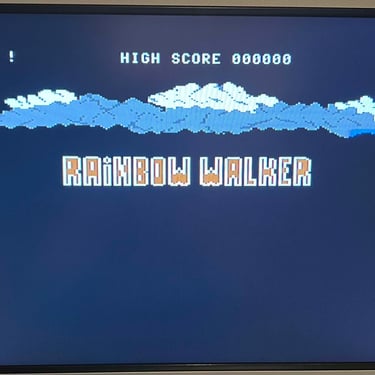
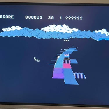
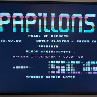
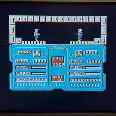
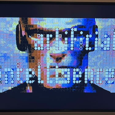
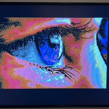
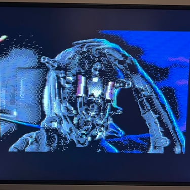
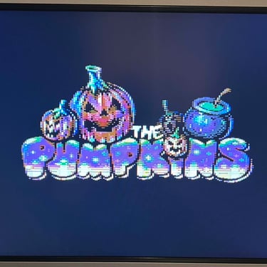
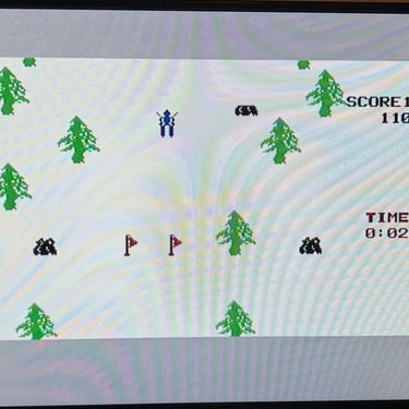
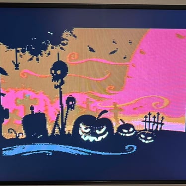
Knowing that the basic functionality of the machine works I continue the testing by using the Commodore 64 for normal operations; playing some games, watching demos, loading from datasette and floppy and using a cartridge. I can not find any issues with this machine. I also pay special attention to the video to make sure that there are no glitches in the graphics - I can´t see any abnormalities. Below is a gallery with pictures from the testing.


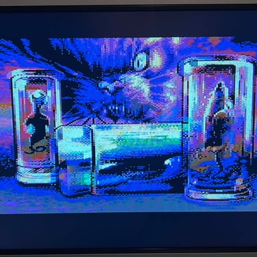
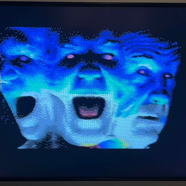
Final result
"A picture worth a thousand words"
Below is a collection of the final result from the refurbishment of this C64 breadbin. Hope you like it! Click to enlarge!

Banner picture credits: Evan-Amos