

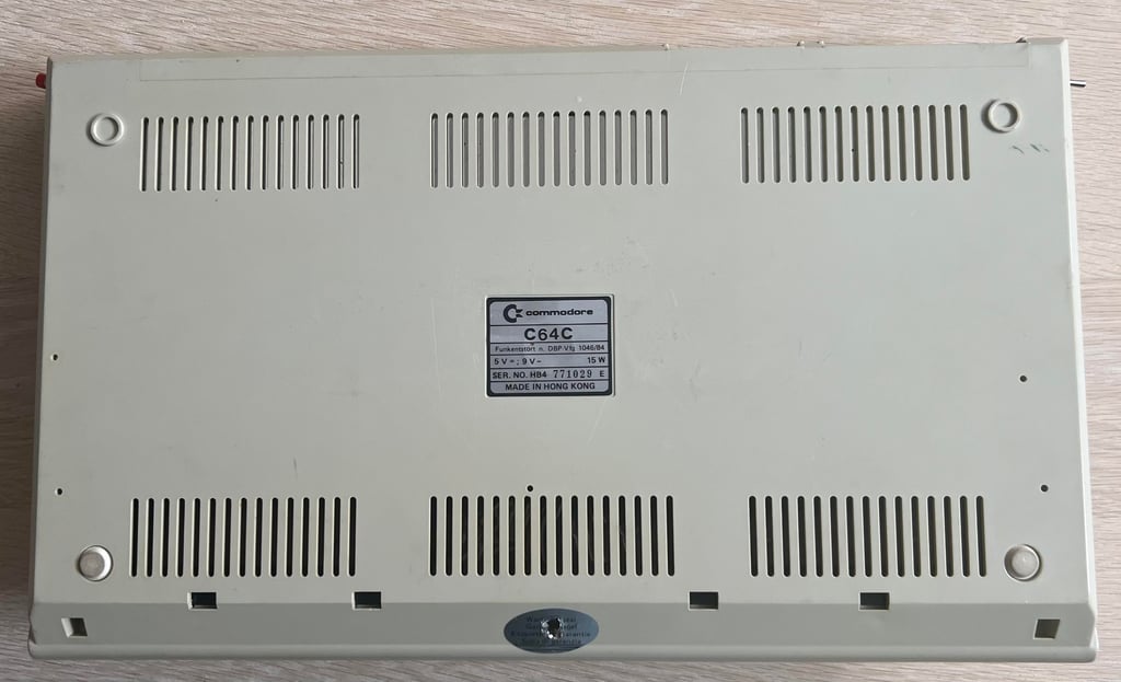
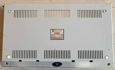
C64C [PAL]
Ser. No. 771029
Assy 250469
Artwork 252311 (REV 4)
Starting point
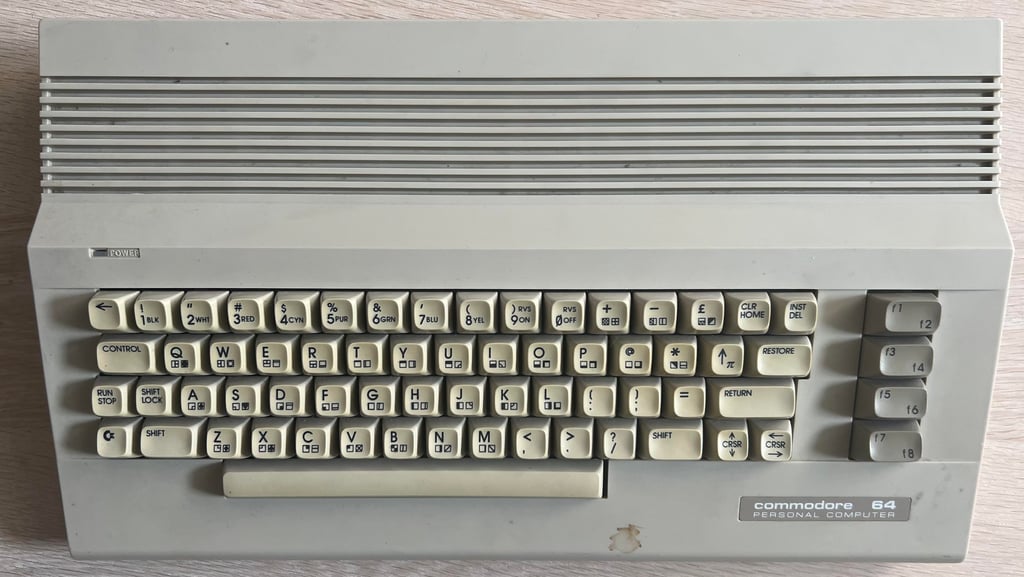
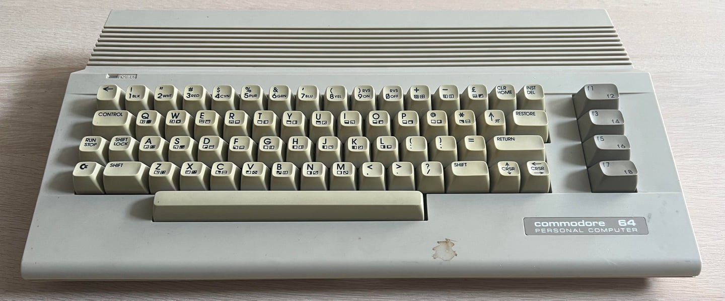
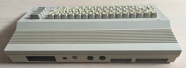
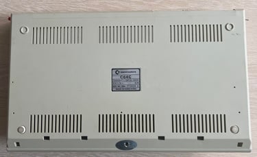
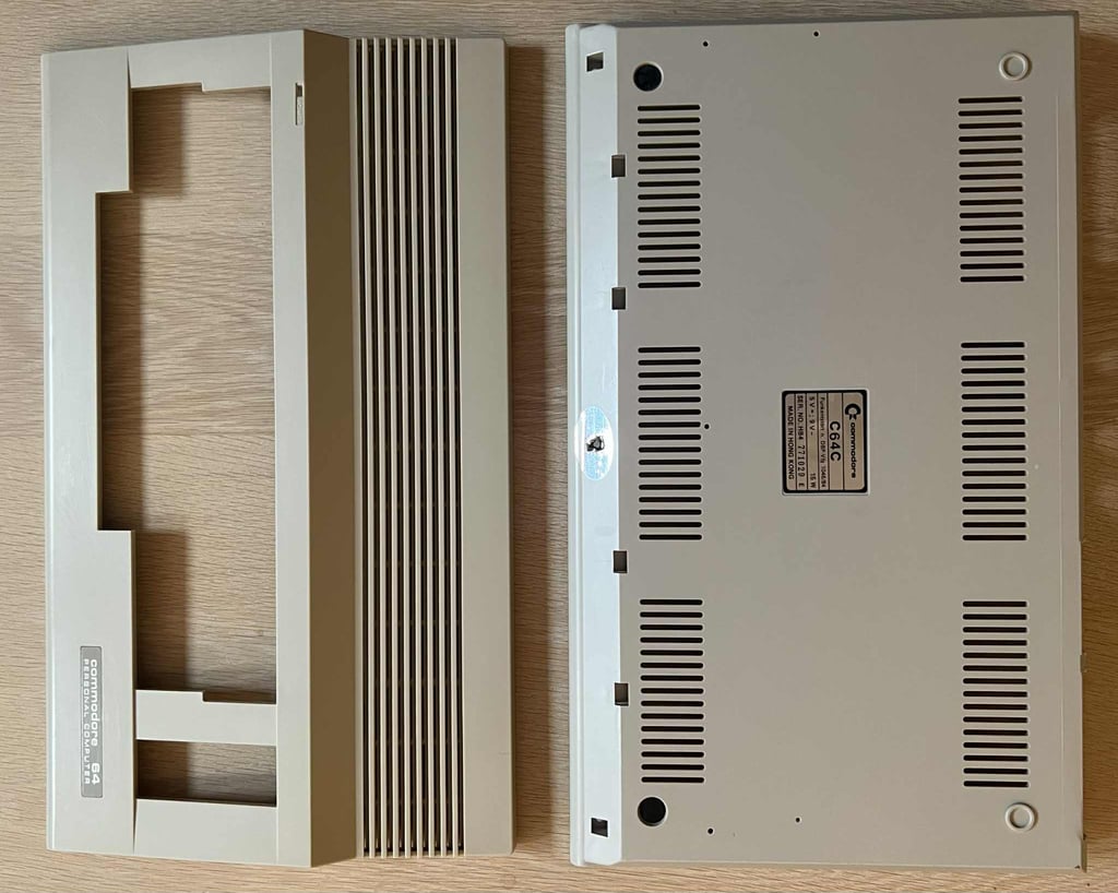
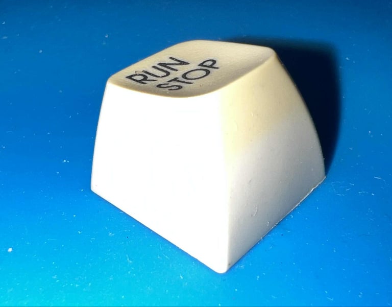
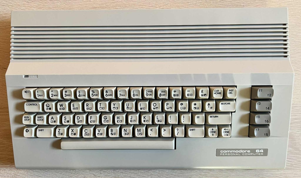
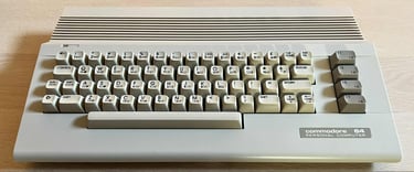
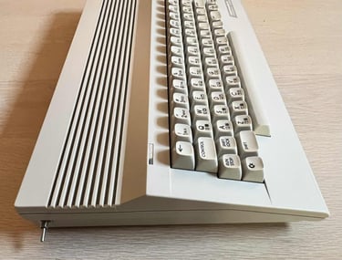
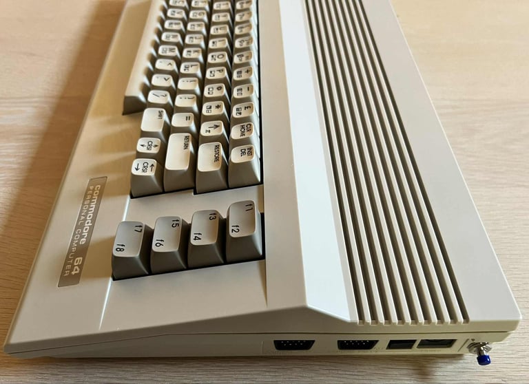
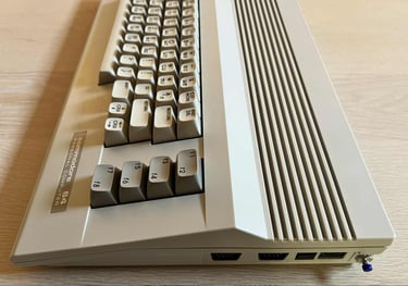
From an overall perspective this C64C looks to be in quite good condition. Yes, it is quite dirty, stained and yellowed - but aside from that it appears to be ok. I can not see any damage or cable "burn" marks on the covers.
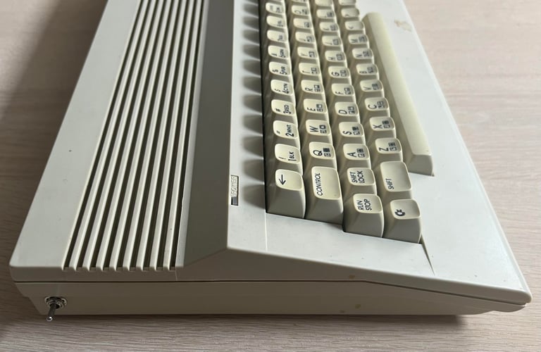
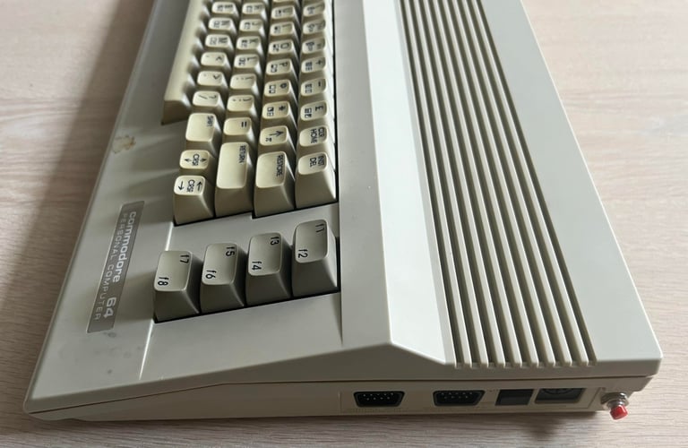
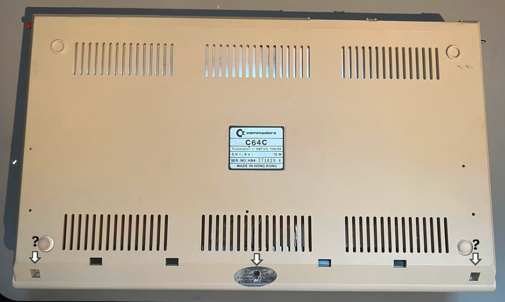
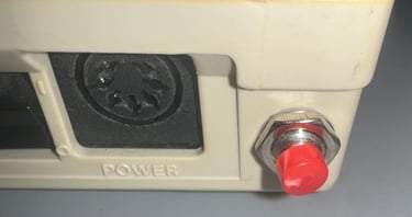
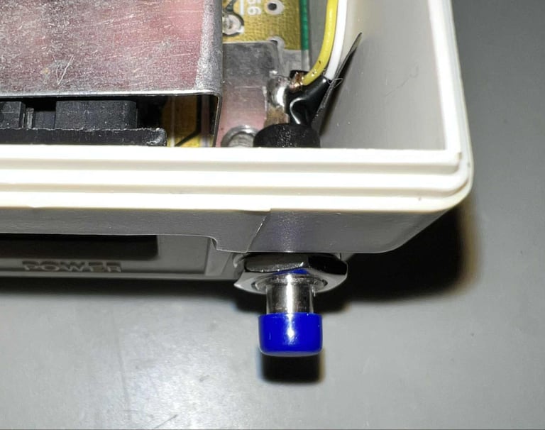
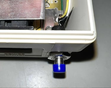
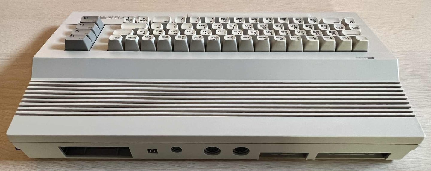
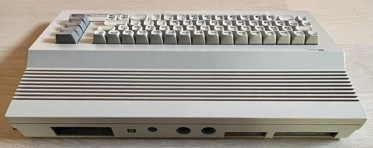
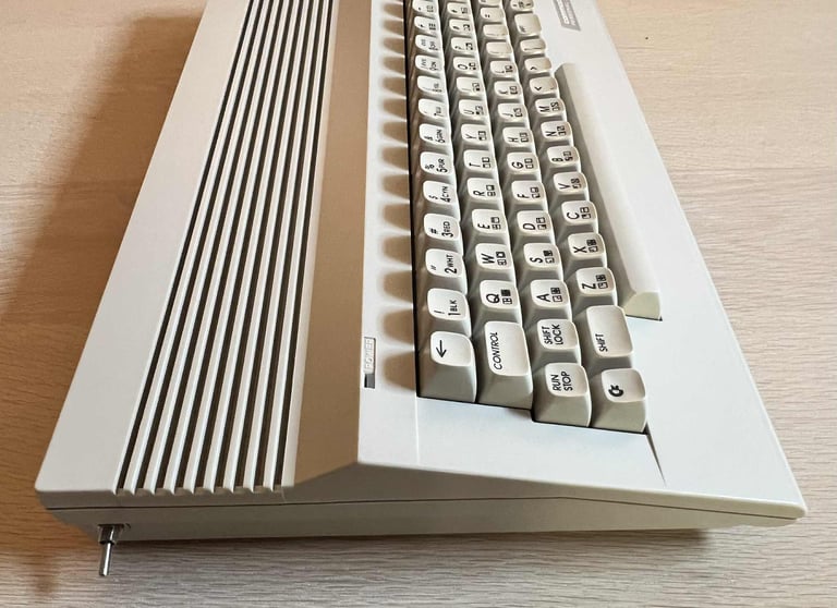
There are two unoriginal switches; a push button on the right side and a toggle switch on the left side. The push button on the right I assume is a reset switch, but the button is completely stuck. The toggle switch on the left I would guess is a Kernal switcher (toggle between an original Commodore Kernal and a 3rd party ROM). This switch appear to be in mechanical working condition.
As with the push button the power switch is also completely stuck in "OFF" position. It is not possible to move it at all (or more precisely: I do not dare to push it too hard damaging it).
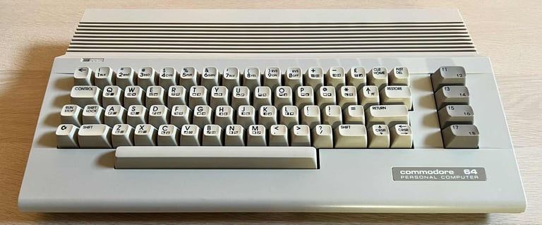
Regarding yellowing the covers are quite yellowed, but it is not completely Gouda cheese. The keycaps on the other hand has yellowed quite a lot.
Two out of the three screws at the bottom are missing.
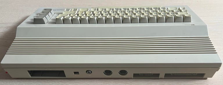
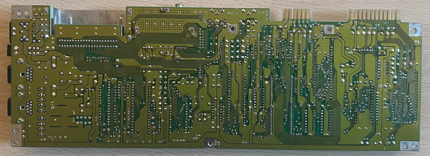
Below are some pictures of the Commodore 64C before refurbishment.


Refurbishment plan
The refurbishment plan for this C64C (order can vary and some of the tasks will be done in parallell):
- Clean and remove stains from the chassis
- Clean and restore the keyboard
- Refurbish main board (cleaning, checking, repairing, replacing capacitors etc.)
- Replace the RF-modulator with C64 Shortboard RF replacement V2
- Verify operation by testing
The plan can be updated during the refurbishment process. Sometimes I discover areas that needs special attention.
Disassembly
To open the C64C the three... eh... one... screw is removed from the bottom cover. The two missing screws will need to replaced during refurbishment.

The top cover is carefully lifted about 30 degrees and then wiggled back and forth until the rear clips leave the bottom cover. At first glance the interior appear to be in fine condition. Quite some dust, but after 30+ years this is to be expected.
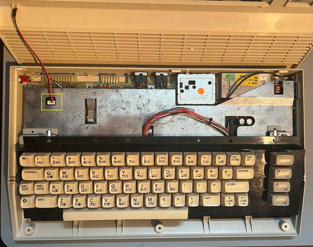

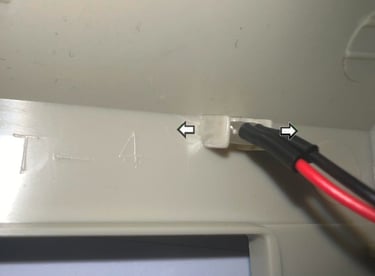
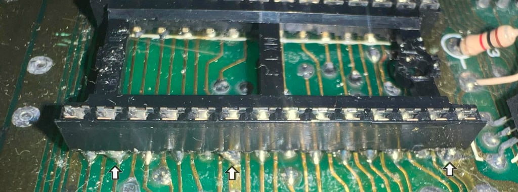
To remove the keyboard the two machine screws (see arrows) are unscrewed and the keyboard lifted away. The keyboard connector underneath is disconnected from the mainboard. Finally the LED connector is disconnected from the mainboard. The top cover, keyboard and bottom cover are now separated. There is very little rust on the RF-/heat shield.
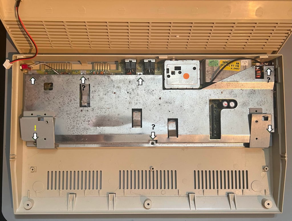
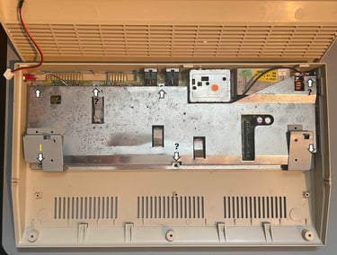
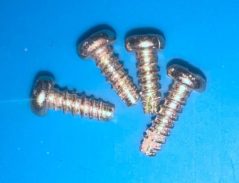
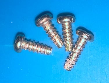
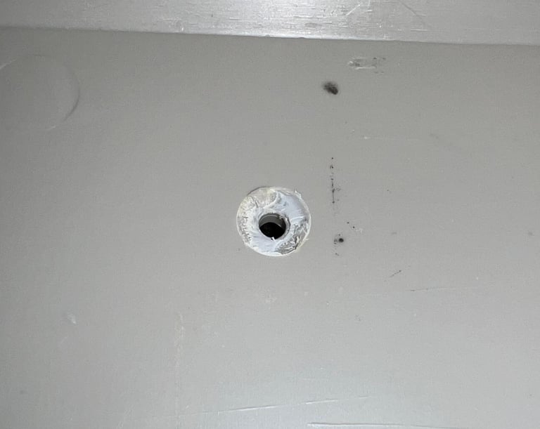
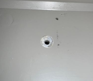
Three out of the seven screws fastening the PCB and shield to the bottom cover are missing. Also, it turns out that the screw at the left bottom corner is longer than the rest (10 mm vs. 8 mm). I am not really sure if this is correct or not (?). I makes sense that the screw at the bottom left and right side should have slightly longer screws due to the additional metal brackets at these places. But due to this slightly oversized (?) screw the plastic standoff beneath the PCB is broken is this place - needs to be glued back as part of the refurbishment.
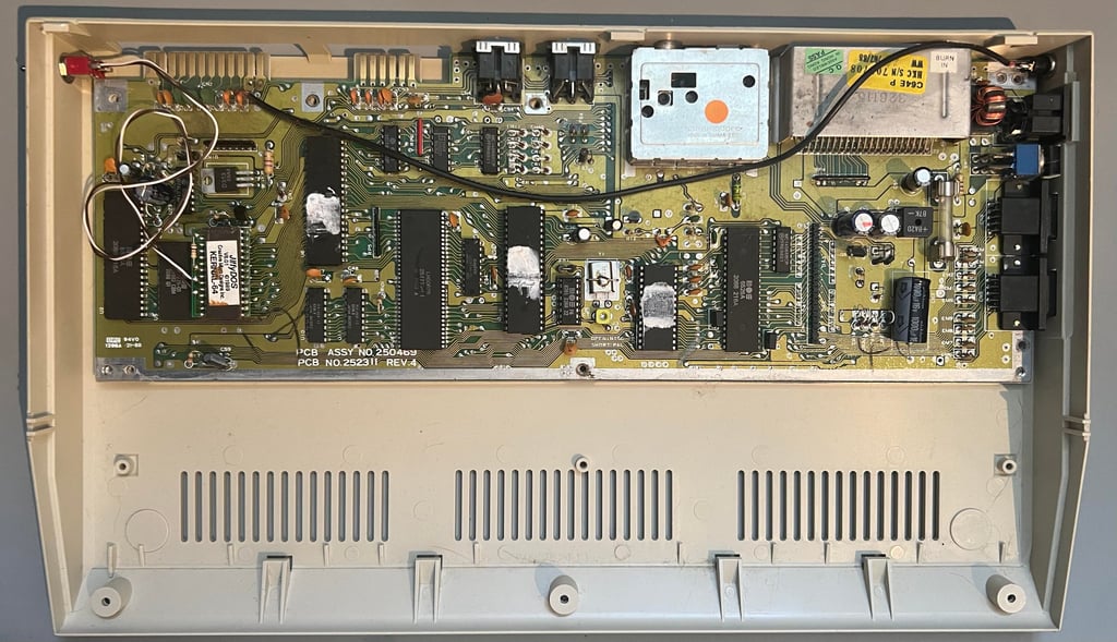
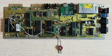
With the RF/heat shield out of the way the mainboard is exposed. It looks to be in quite condition - but it is quite dirty (the picture does not do justice as it is more dirty in reality). Now I also can see that the toggle switch controls a 3rd party ROM: JiffyDOS! And the push button is a good traditional reset button soldered to the user port. All the old heat paste have completely dried out (which is to be expected).

Exterior casing
In short: dirty, stained and yellowed, and with a broken stand-off. To start the cleaning process the LED is removed first by carefully push the small (brittle) plastic arms away from the LED.

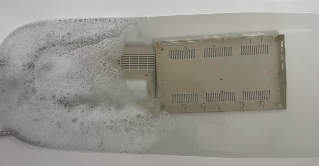
With the LED out of the way the covers are soaked in mild soap water for about 48 hours. This will dissolve most of the old dirt and grease. A perfectly cleaned cover is crucial for a later successful retrobright.

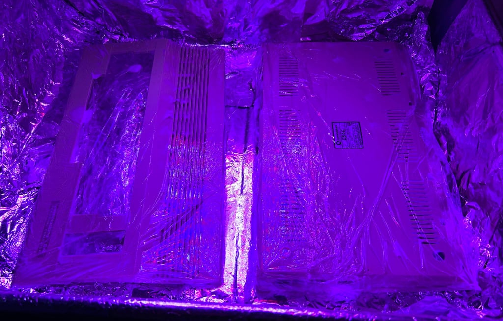
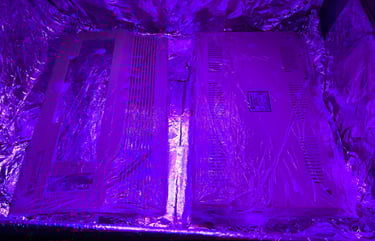
After cleaning the top- and bottom covers are retrobrighted. This is done by applying 12 % hydrogen peroxide cream to the covers and exposing them to UV for about 12 hours. The hydrogen peroxide cream is replenished frequently to avoid drying out - and in addition the covers are wrapped in cling plastic.
The result after retrobrighting is quite good. Most of the yellowing is now gone.

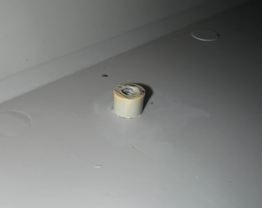
The broken stand-off is glued back to the bottom cover. This will probably not last forever, but it should be sufficient for now.

Keyboard
The keyboard appears to be in quite good condition. Apart from being a bit yellowed it seems to be without any damage.
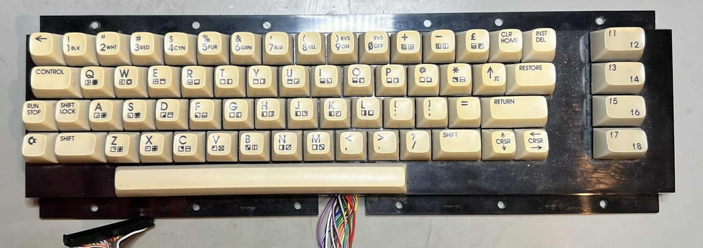
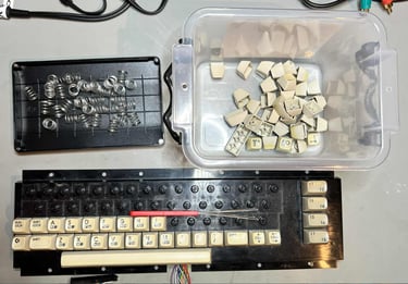
First, all the keycaps are removed. These are removed by using a keycap puller. The keycap puller will reduce the risk of damaging both the keycaps and plungers (and your fingers for that matter). Please note that the there is a spring beneath each keycap, and that the spring beneath the spacebar is slightly larger than the rest - so it is good practice to keep this in a separate plastic bag.
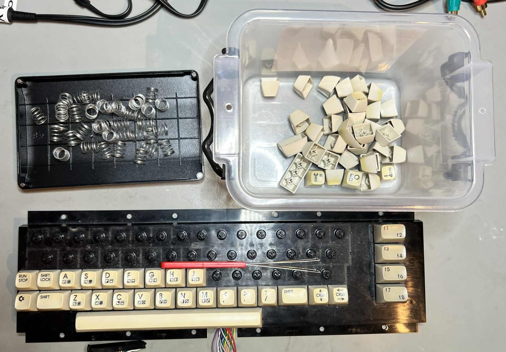
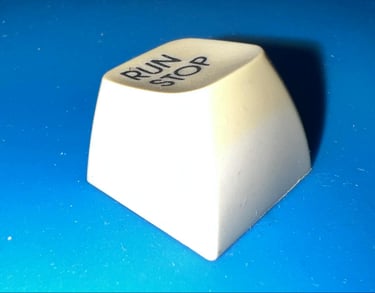
Only some areas of the keycaps are yellowed. Mostly the top side and front side (this is very common) as can be seen from the keycap below.
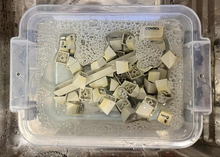
A prerequisite for a successful retrobrigting is clean keycaps. Therefor all the keycaps are placed in a box filled with mild soap water for about 24 hours. This will dissolve most of the dirt and grease covering the keycaps.

Removing the SHIFT-LOCK switch from the keyboard is not complicated, but it is very nice to know how to remove it: first the two wires at the back are desoldered from the switch, then the SHIFT-LOCK switch is pushed firmly from the backside of the keyboard towards the front. This will make the SHIFT-LOCK switch pop out. The SHIFT-LOCK key is cleaned properly with isopropanol.

With the SHIFT-LOCK switch out of the way the keyboard PCB can be removed. This is achieved by removing all the tiny small screws at the backside (with a PH2 screwdriver and low torque).

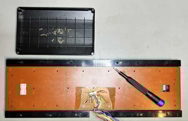
The keyboard PCB is a Mitsumi KSR-A66YF 56 4021 B-01 which is equipped with carbon pads. To clean the carbon pads some distilled water (and NOT isopropanol) is used to clean the keyboard PCB. After cleaning the PCB looks good as new.

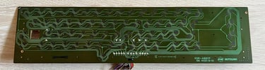
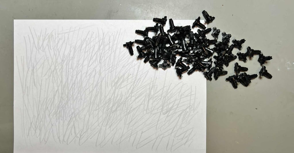
To revive the plungers a small trick is used: by carefully dragging the plungers across a clean paper sheet the dust and grease covering the conductive rubber is removed. This is the most gentle, and effective way, to revive the plungers.
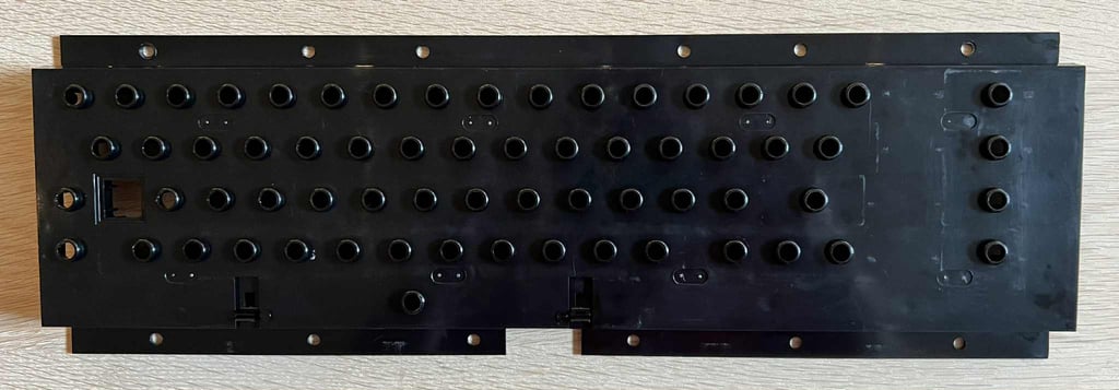
The plastic frame, holding all the plungers, is cleaned with mild soap water and a soft paint brush. After cleaning the plastic frame looks as new.
Mainboard
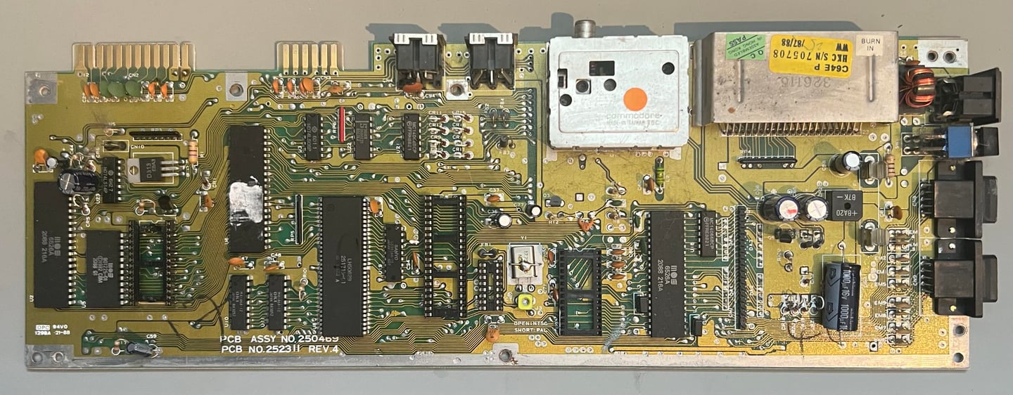
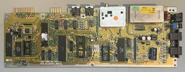
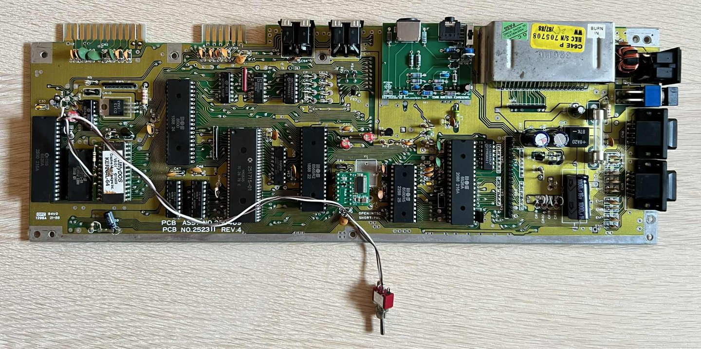
This is a Assy 250469 / Artwork 252311 (Rev 4) mainboard which is one of the common "shortboards". The shortboards have fewer components compared to the old breadbin (and "longboards") as several of the logic ICs are now part of the extended "PLA" IC. The latest revisions of the shortboard even has the color RAM integrated in the "PLA" IC. Shortboards also have the MOS 8500 CPU and MOS 8580 SID chip.
Before the visual inspection the needs to be properly cleaned. All socketed ICs are removed and both the push- and toggle switch are removed before cleaning. Below is a picture of the mainboard before cleaning.
Visual inspection
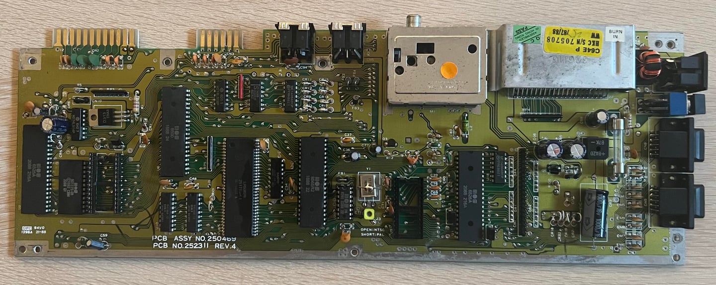
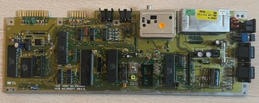
The mainboard appears to be in good general condition after cleaning. I do not see any major damages, corrosion, leaking capacitors or other oddities. Some other observations:
The power switch is as mentioned previously completely stuck. But there are no external visual damage to the switch that cause this jamming.
The Kernal socket is not very well soldered in place. It would probably work, but some of the solder points are not too good.
The reset push button is also stuck.
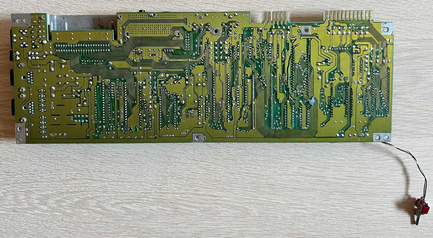
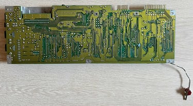
Below are some pictures of the Kernal ROM socket (on both sides of the mainboard). There are some poor solder joints here. If it turns out that the machine does work like this it is probably best to just keep it like this to avoid damaging traces or pads. If not ther Kernal socket needs to be replaced.

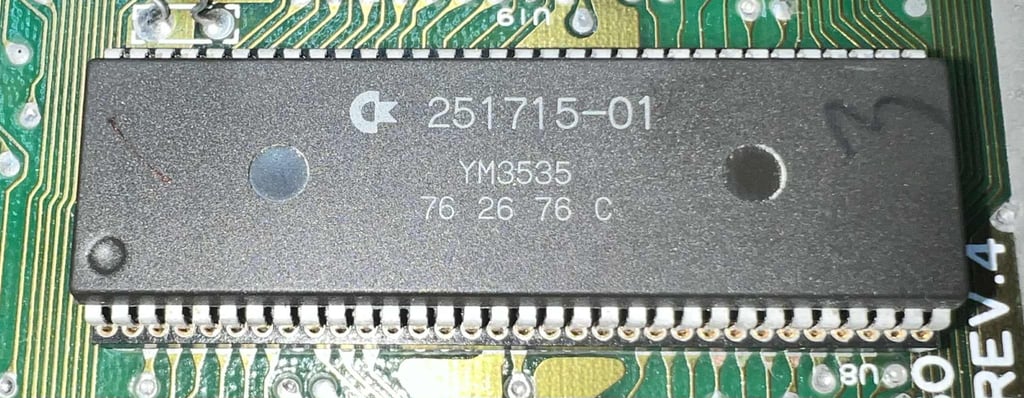
In the table below the custom ICs are listed. As can be seen from the table below it is likely that this Commodore 64C was manufactured during the summer of 1988 - just in time of the opening of the Summer Olympics in Seoul (?). Whether or not the owner of this Commodore 64C listened to the magnificent album Seventh Son of a Seventh Son from Iron Maiden the same year I leave for the reader to guess.
Repairing the power switch (SW1) and push button
Before initial testing can start the power switch needs to be fixed. Hopefully this can be done by refurbishing the existing switch. If not, a new power switch will be sourced.
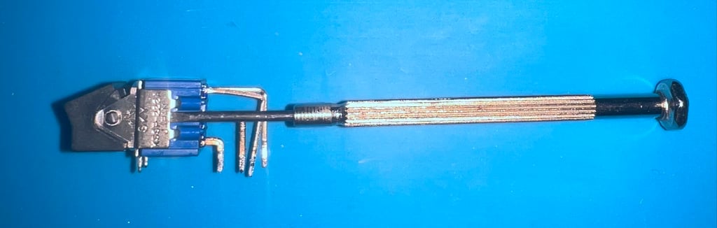
Refurbishing the power switch (SW1) is not very complex, but it is a bit fiddly. First the power switch is desoldered from the mainboard. No traces or pads were damaged during the desoldering.

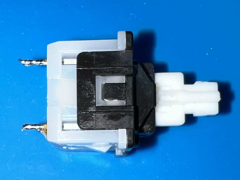
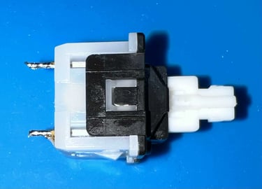
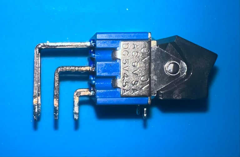
The desoldered power switch has no visual exterior damage which should case it to jam. Quite opposite, it looks to be in good condition. The power switch is used both for the AC and DC rail from the power supply (rated at 9 VAC (3A) and 5VDC (4.5 A)).
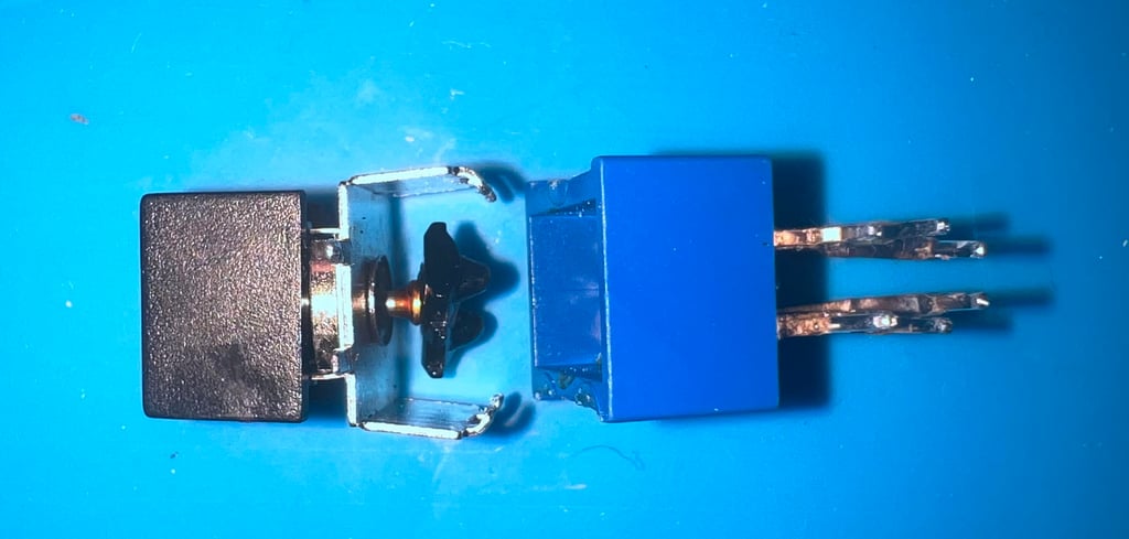
Since there are no exterior sign of damage the power switch is opened. This is done by carefully prying it open with a thin flat screwdriver. Make sure not to pry and bent more than absolutely necessary.
The "rocker" and the base is separated by gently dragging the parts away from each other.

All the tiny parts are cleaned individually with a cocktail of contact cleaner and isopropanol. Note that (I think) these switches are lubcrated with some kind of grease originally. But I do not know which kind of grease this is so I do not replenish this. Also, I think that the grease could cause a voltage drop in the Commodore 64 later if the metal plates inside the switch gets dirty. Below is a picture of the all the cleaned parts.
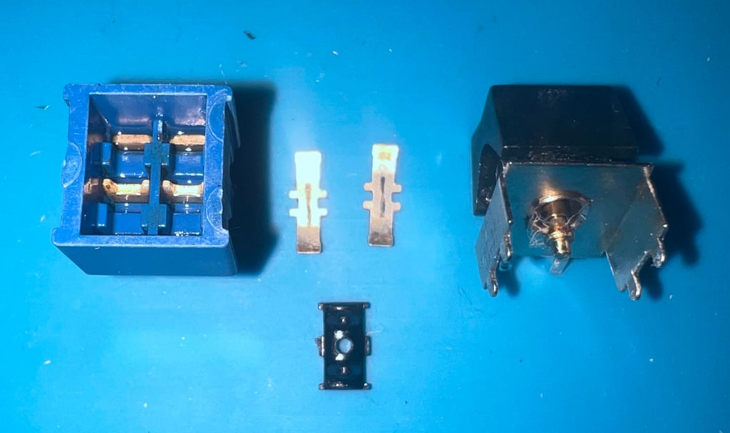

As can be seen from the picture above all the parts appears to be in very good condition (after cleaning). I can not see any obvious reason why the switch should be completely stuck. When the power switch is re-assembled it works fine, but now I notice that it is very stiff. It is possible to turn the switch ON/OFF, but it feels quite hard. Could this be due to some missing lubrication? Maybe, but I do not really think so. I actually think that the problem is that this switch has some marginally larger interior parts making it a quite tight space. This will then require the user to apply some more force to toggle the switch in ON/OFF position. Nevertheless, the switch now works and I will leave it like this for now. If it turns out that the switch jam again during refurbishment it will be replaced.
Repairing the reset push button
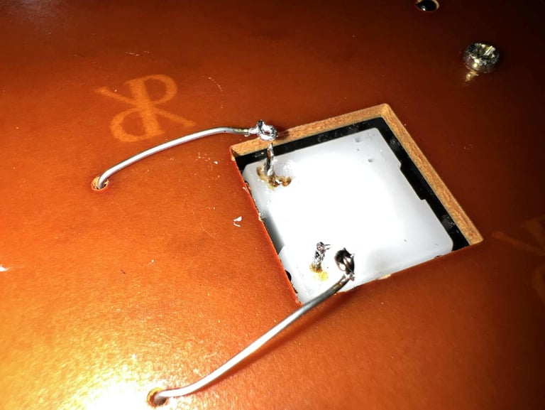
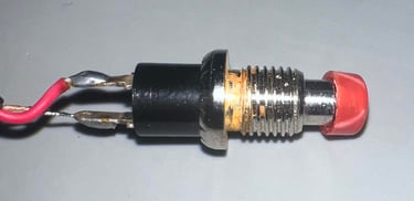
The push reset button is also completely stuck. With closer inspection it seems like the top of the button is slightly bent. See picture below (this is perhaps not so easy to see, but pay close attention to the top hat of the button).

To repair the push button the top is gently moved back to original position. This makes the button work again. I will try with this solution first to see if the button now works as it should or if the problem reoccur. Below is a picture taken during the repair prosess (about 75 % complete).

Initial testing
With the repaired power switch soldered back in it is time to do an initial test of the Commodore 64C. Now I feel that the power switch feels very stiff so it probably needs to be replaced, but it will work for now.
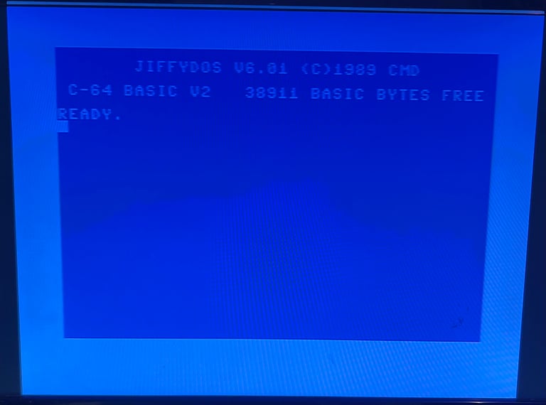
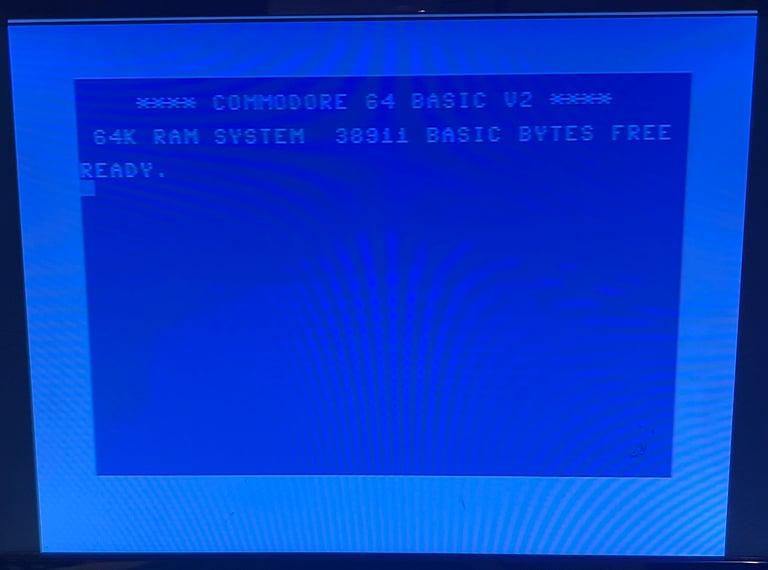
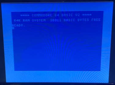
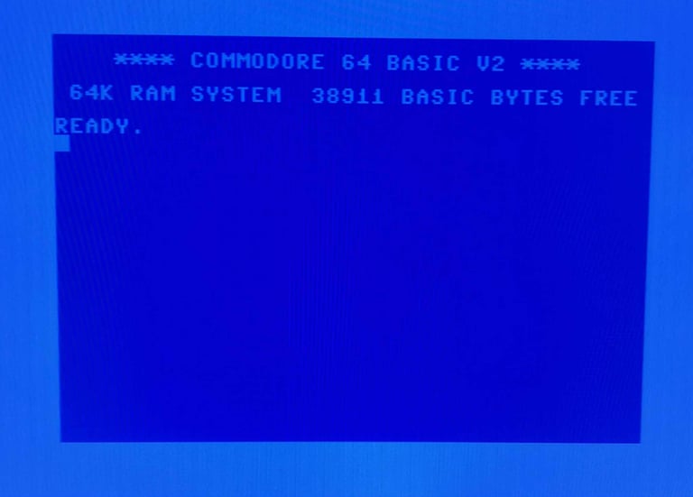
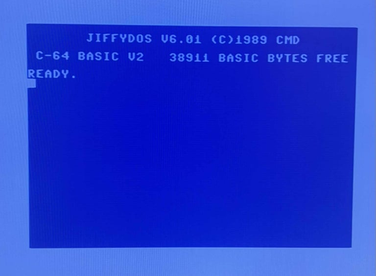
Powering on the Commodore 64 results in a: NORMAL BLUE BOOTUP SCREEN (WITH JIFFYDOS OR COMMODORE KERNAL)

Checking the voltages
For the Commodore 64C to work flawlessly all the different voltages need to present and within acceptable tolerances. The 5V at the user port is a bit low, but I think that is due to the power supply or the power switch. A detailed article on the subject can be found in the HOWTO - Checking the C64 voltages. In the table below all the measures voltages are listed (this list will also be updated after refurbishment). All the required voltages are present and within tolerances, so there are nothing obvious wrong in that area. NOTE: for those who follow my refurbish project you may notice that many of the voltages appear lower than seen before. The voltages are completely fine, but I am now using a modified C128 PSU which outputs a bit lower voltages - but it is well within tolerances.
Replacing the RF-modulator
From The Retro Channel:
"The RF modulator in the C64 handles amplification and filtering for all video signals (including the ones on the C64 DIN connector). Unfortunately it does a very poor job and this is even more apparent with modern displays and upscalers, even CRTs with their inherent softening can reveal issues with the original RF modulator. One way to signifcantly improve the video output is to replace the RF modulator with a more modern and finely tuned solution, and why not add a few quality of life features while were at it."
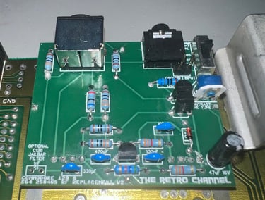
The Retro Channels have designed what is probably the best analog RF-modulator available. And the design is open-source. I order the PCB from PCBWay and components are ordered from Mouser Electronics. Below is a picture of the fully assembled RF-modulator replacement.

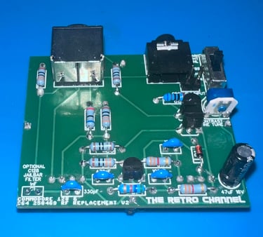
NOTE: I managed to purchase the a standing, instead of a flat, 500 Ohm potentiometer from Mouser. Adjusting the fine tuning can still be done with a thin flat screwdriver, but it is a bit awkward. Sorry.
To install the RF-modulator replacement the old RF-modulator needs to be removed obviously. Removing the old RF-modulator is not very complex, but I would recommend following some guidelines to prevent damaging either the old RF-modulator or the mainboard. Since the RF-modulator is a device in itself, and soldered directly to the mainboard, it can easily do damage if not careful. Please see this article on how to desolder the RF-modulator.
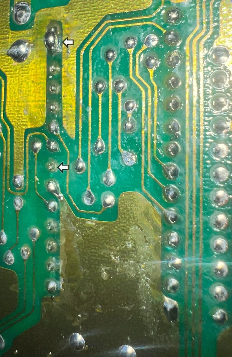
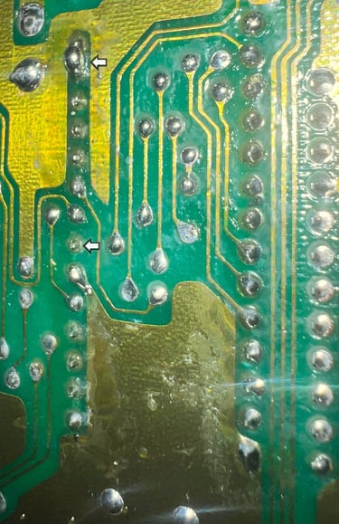
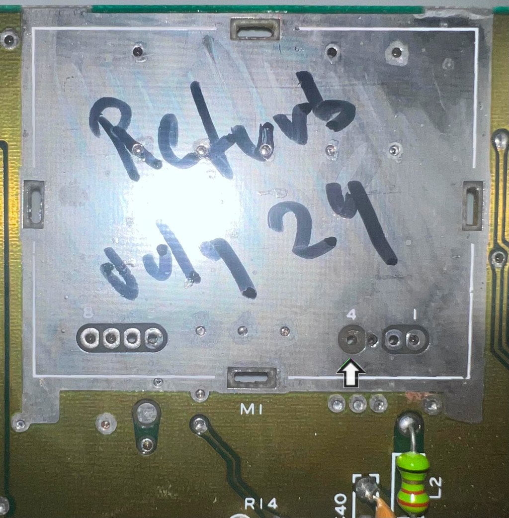
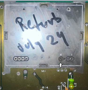
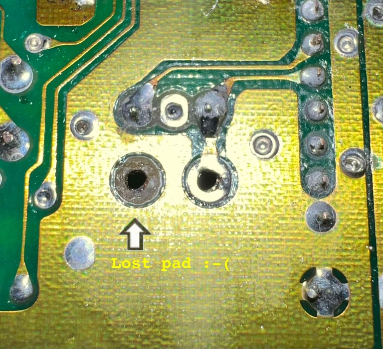
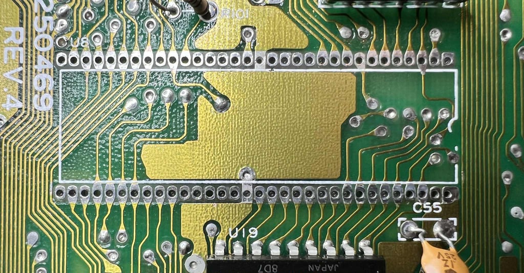
The RF-modulator is desoldered, but one of the pads were lifter (pin 4 on top side of mainboard). This does not need any repair though since this pad is not connected to anything on the top side (and the pad on the bottom side of the mainboard is not damaged - and is where the pin is connected). See picture below of the desoldered area, and the arrow mark the missing pad.
Finally, the new RF-modulator replacement is soldered to the mainboard.

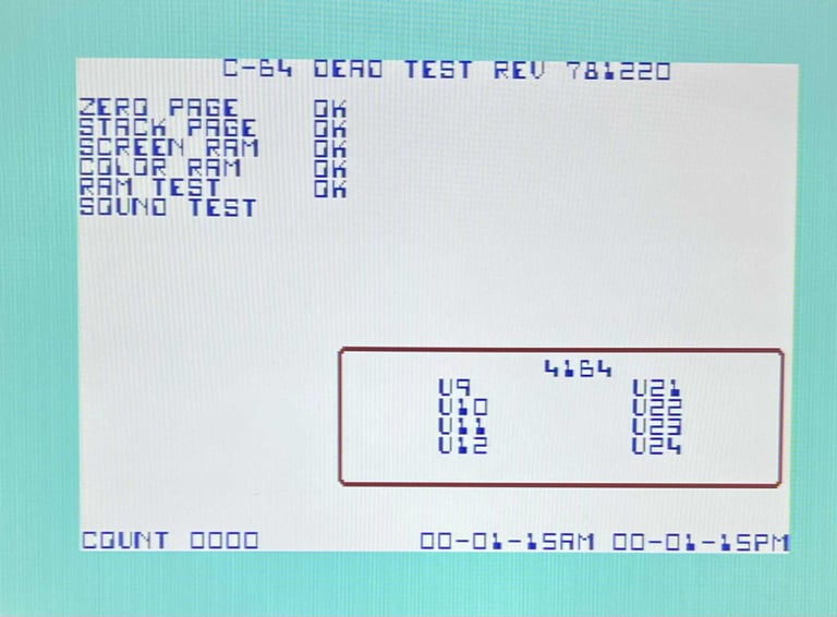
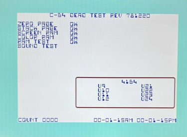
Continuing testing - Dead Test Cartrigde
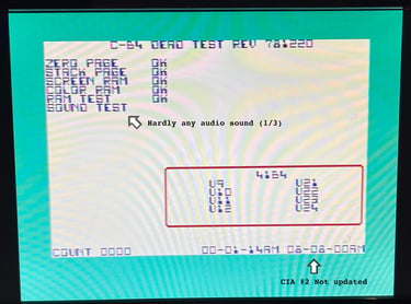
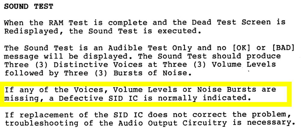
In hindsight I should have done the test with the Dead Test prior to installing the RF-modulator replacement. Well, live and learn I guess. Nevertheless, when running the Dead Test Cartridge I do notice three things:
The CIA #2 (U2) internal Time of Day clock is not being updated
The SID chip produces only a very low sound in one out of the three sound tests
The picture is starting flickering when the mainboard is pressed down (and settles in this way eventually)
See picture below.

Mainboard - Repair
What at first glance seemed like a non-repair refurbished turned into a repair. Nice! Joke aside, these things happens. The Commodore 64 is an old machine and faults occur frequently.
Replacing the power switch
Although the refurbish of the original power switch did improve the situation (it now powers on) I am not satisfied with it. The switch is really hard to toggle. So a spare power switch is taken from another Commodore 64 (Ser. No. 828599). The "new" power switch is soldered in and the machine powers on as normal.
Re-inserting the original RF-modulator
Could the RF-modulator replacement have caused the problem with the flickering picture? An the low audio? I do think that there is a chance that this could be the case, so the original RF-modulator is soldered back in. The result is that the flickering is gone, but the audio is still hardly audible.
Checking the MOS SID 8580 chip
The MOS SID 8580 chip contains analog elements internally which I believe could be causing the very low audible output. The chip is tested in another know working C64C. The result is that this chip does seems to be working just fine in another machine. So apparently there must be something else going on the mainboard.
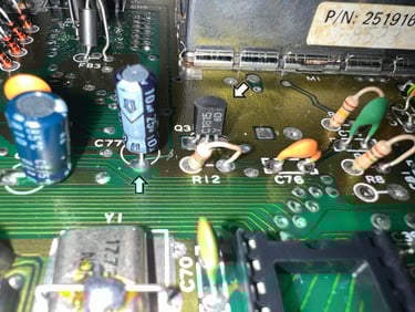
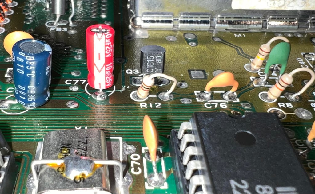
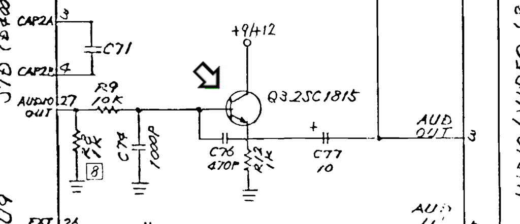
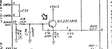
The analog signal is output on pin 27 on the SID chip, amplified in the Q3 transistor and feed to pin 3 on the RF-modulator as can be seen from the schematics (#252312). Since the SID chip itself appear to be working I would assume that there could be a fault in this amplification network (a bad transistor, capacitor or resistor).
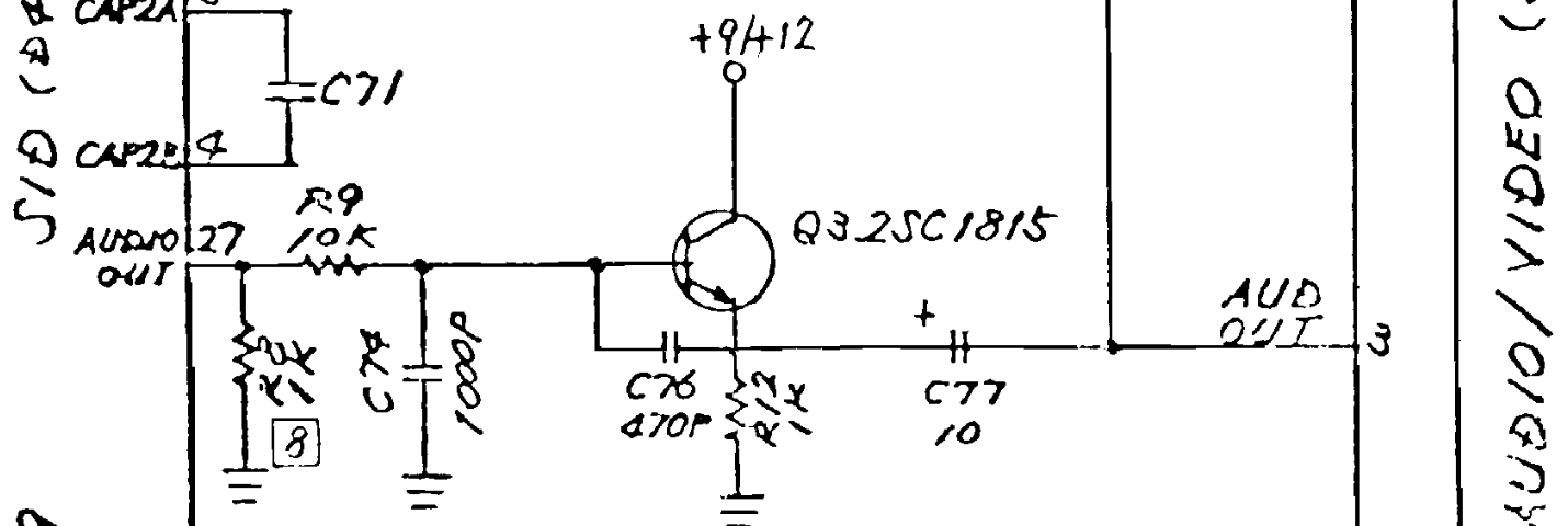
Resistors can fail, but it is not as usual as transistors and capacitors. I will therefore start with these components. There are two components which stand out as possible fault candidates:
C 1815NPN transistor (Q3) which amplifies the signal from pin #27 at the SID chip
10 uF [25 V] electrolytic capacitor (C77) which acts as a filter between the transistor output the RF-modulator input (pin 3)

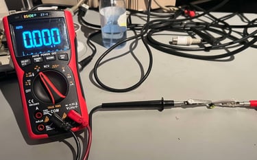
Checking the NPN C1815 can be done in circuit. By setting the multimeter in diode mode the voltage drop between BASE -> COLLECTOR and BASE -> EMITTER (and vice versa) can be measured. The rule of thumb is that if these measures equal (in each direction) the transistor is fine. As can be seen from the table below these voltages appear to correct, so I do not suspect the transistor to be bad.
Now something odd happens. By chance I test the machine with the Dead Test cartridge - and the audio now works! But ONLY in the first run of the Dead Test procedure. Could this fault be caused by something getting warmed up and stop working?
Checking the 10 uF electrolytic capacitor (C77) in circuit measures about 20 uF. I think this "misreading" is due to being in circuit. These electrolytic capacitors are known for drying out after years, so it is good practice to replace them. A new capacitor is installed.
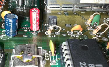
The result after replacing the C77 capacitor is that audio now works! It needs to be tested further, but so far it works. I will let it run for a few hours and also try to press different areas on the mainboard to see if something could cause the problem.
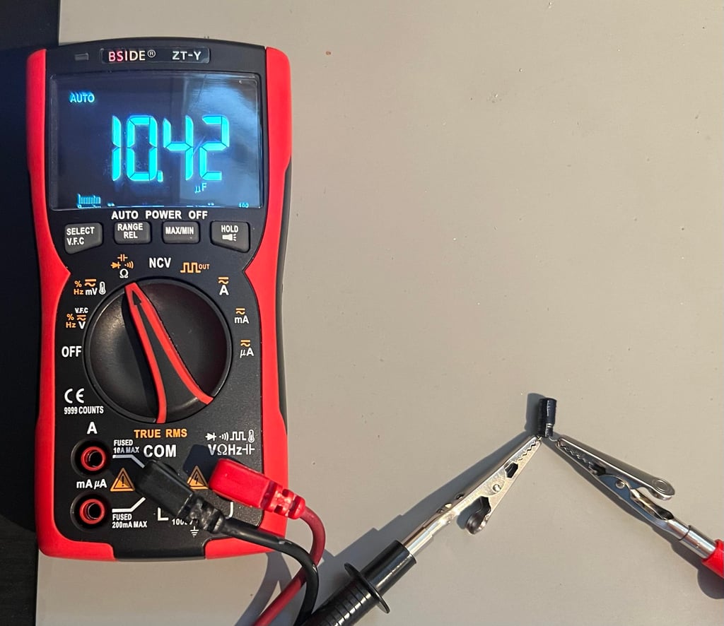
Note that even if the C77 seems to be ok after desoldering and checking this with a multimeter - it is faulty. As can be seen from the picture below the capacitor reads fine (10 uF), but it still turn out bad? Is it really bad - or did the replacement actually fix something else?

After letting the Dead Test run for 3-4 times something starts to happen. The Dead Test program test the SID chip running sound through the three voices, but after some time running one of these voices seems to be completely gone (or with very low sound)? So I am starting to wonder if the SID chip is marginal. From the Dead Test manual we can read the following:

A step back - what are the faults actually?
Sometimes it is good to take a step back and evaluate the situation. It turns out that even if this machine boots normal, there is something very strange happening when the machine is running for a while. This is not easily detected when the machine is only showing the normal blue screen, but when the Dead Test Cartridge is installed something strange starts to happen...
The symptoms vary from time to time, but this is a typical description of the situation. Please note that the SID chip is removed now, the combined Kernal/BASIC ROM is removed, the MOS 6526 CIA #2 is removed and the original RF-modulator is installed. All this is done to try to reduce the number of chips and modules that could cause faults - but are not required for the Dead Test Cartridge to run.
The situation:
The Dead Test program runs fine for 1-2 rounds. There are of course no audio, and the CIA #2 shows wrong timing, but otherwise everything is ok.
Small thin, flikcering, stripes of disturbance appear on the screen. They look "analog", but I am not really sure what this is.
The whole screens get "darker" and the colors seems wrong. There are colors, but they appear very different.
Some of the characters get wrong colour. Almost like the color RAM is bad.
Test starts to fail: Zero page BAD, Color RAM BAD etc.
The whole screen starts flickering heavily. It is like the whole machine is going down in a major crash - and finally it does
Powering on the machine AFTER such a crash shows only a black screen. When the machine has cooled down the process described above repeats.
In the video shown below you can see an example of how the situation look. Please note that no SID or CIA #2 are installed at this moment and will therefore not show correct results. In this test everything "passes", but the colours are wrong. If I had recorded even longer the tests would have failed also and the machine would have come to a halt.
Things to notice in the video:
0:00 - 00:52: Everything works as it should. All tests pass and colours are ok.
00:52 - 00:53: First signs of flickering on the screen
00:58: The screen is "dimmed" (?) and changes abruptly
1:12 - end: The screen comes back but the colour saturation looks very odd.

What we know so far
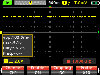
Using an oscilloscope has proven valuable. When the situation described above starts, there is obviously something happening on the clock signals:
When measuring on PIN #1 on the CPU (Phi0) the clock is dead steady when everything on the screen is normal (check signal reference here). But when the first "analog looking" faults starts to visualise, the amplitude on the clock signals drops a bit and/or starts to oscillate. As the Dead Test cartridge runs the software this clock signals gets worse and worse. Amplitude oscillates more and more, the signals itself starts to stop/start/jitter and finally the signals goes completely dead - and so does the machine.
The hypothesis
My hypothesis is that there is something wrong with the stability of the clock generating circuit. It could be the ICs related to the clock generation such as the MOS 8565 VIC-II and/or the MOS 8701 clock generator. Also, it could be related to the analog circuits used by these such as the capacitors, crystal and variable resistor.
Troubleshooting
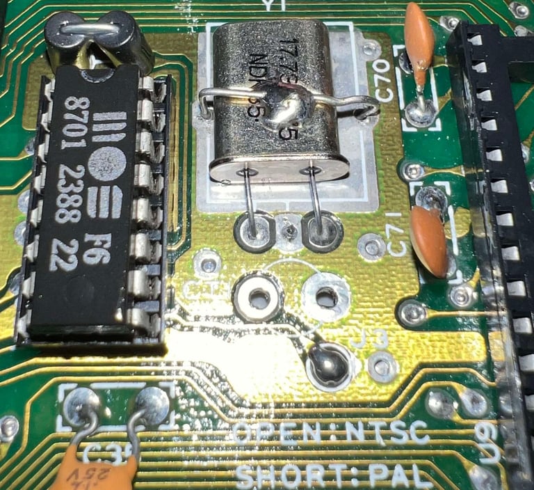
The easiest, and fastest, to check is to see if the MOS 8701 and/or the MOS 8565 are faulty. These are replaced with known good working ICs, but it turns out that the machines behaves the same. The machine seems perfectly normal when it is cold, but after some 5-10 minutes things starts to fall apart.
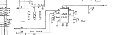
The next step is to check the passive analog components: the oscillator crystal (Y1) and the variable capacitor (CT1). The crystal has a resonance frequency of 17.734472 MHz and the variable capacitor a range between 7.7 pF - 40 pF. See schematics below (From the C64 Service manual - Schematics 252312).

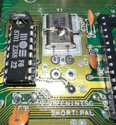
When desoldering the variable capacitor I accidentally loose a pad, but this not very much of a deal since the pad was not connected to anything. But I also see something I think is a bit strange. When I try to measure the capacitor with a multimeter I get no reading at all - or only some flickering reading. It could be that the multimeter is not capable of such small readings, but I am not sure... Could this be a bad capacitor and cause the fault? See pictures below from the process.


The saga continues - and what a mystery...
Replacing the MOS8701 and crystal oscillator
A TOLB module from Eslapion is ordered from retroleum.co.uk. This little circuit replaces the MOS 8701 (and crystal oscillator) should therefore give a very stable clock - both input to the VIC-II and then further on to the CPU.
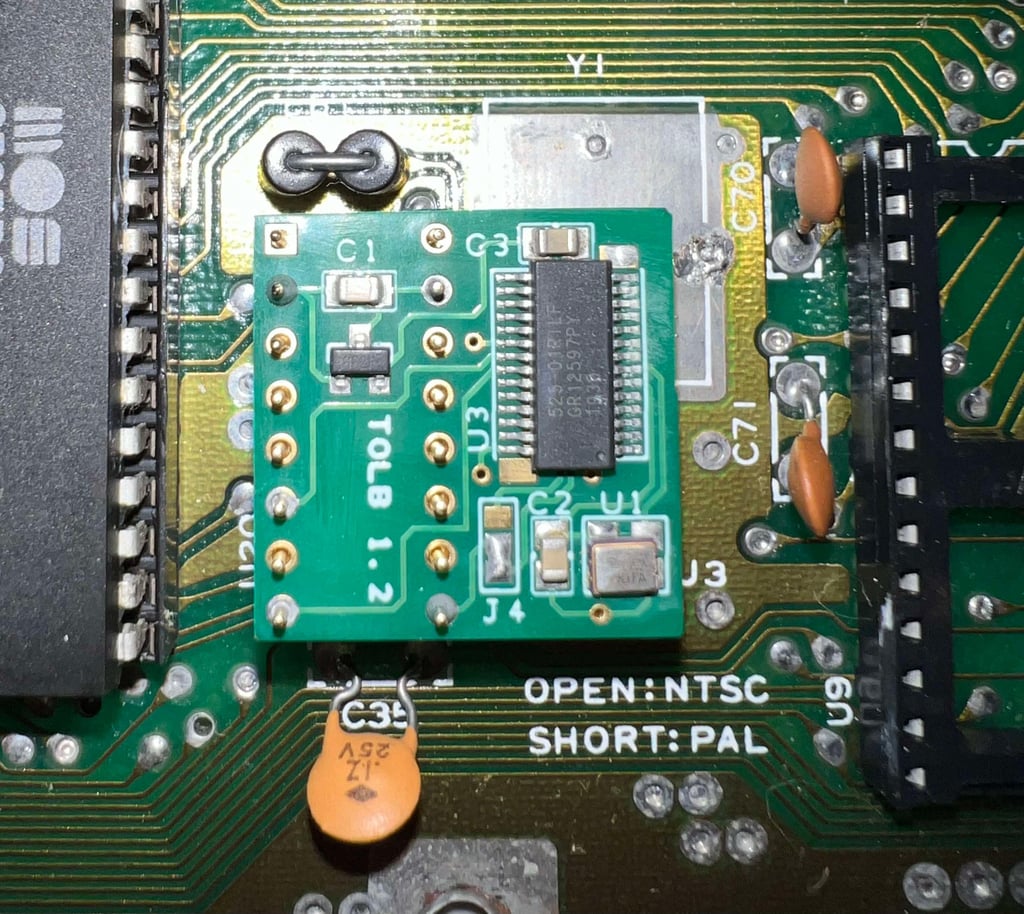

With the new TOLB module in place the Dead Test Cartridge is now running fine again! The tests pass time after time - and no analog flickering on the screen!
... until something really weird happens
To make sure the machine is now "back to normal" it is powered on for a while. But now something strange starts to happens! It is not analog flickering, but some digital corruption which is usually caused by RAM failure. See video below.

What is happening here? I feel the machine is falling apart in my hands! Holy moly, hehe!
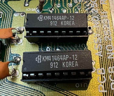
Nevertheless, a couple of new 41464 RAM chips are put in (and sockets installed).

But we are still not out of the woods yet (!)
With the new RAM ICs installed things looks much better again! Phew! The Dead Test Cartridge is running all tests fine - and everything looks normal.
A known good working CIA is installed - and the Dead Test started again. But now things REALLY start to get crazy! After a couple of runs the AM clock increases slightly faster than the PM clock? Why? And after a few more rounds there is WHITE SMOKE coming from the bottom left corner of the CIA IC! Holy macarony! We have a FIRE!

Ok, that was a bit exaggerated (thanks ChatGPT!), but we definitely have a serious issue here with some kind of short circuit!
Looking for a short circuit
I start to think about it. This repair has been quite challenging - as I feel that more and more problem occur as I repair:
Interim problems with audio
Wrong TOD clock on the CIA #2
Oscillator circuit starting to get flaky before it finally stops working completely
RAM chips starts to suddenly fail
Smoke coming from the CIA #2 (new)
Have I been chasing the wrong fault all the time? Is it so that the "real" fault is causing more and more damage as the repair goes on?
In case you wonder: No, I do not use an old power PSU. I use a modern replacement (which I know is working). But this is kind of the same behaviour you would expect if you had a bad power supply basically "killing" all your ICs as you go.
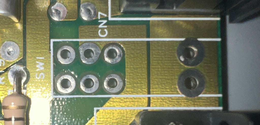
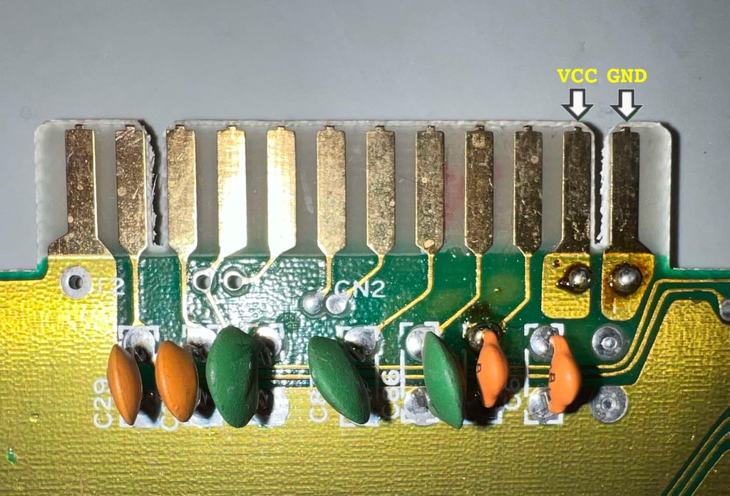
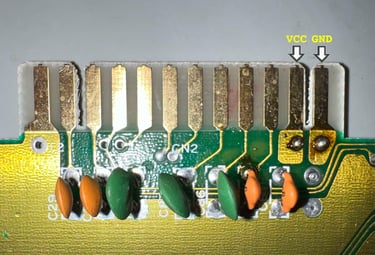
There is a good spot to check if there is a short circuit on the +5 VDC rail: the USER PORT. In the picture below you can see the user port and where the +5VDC (VCC) and ground (GND) connector can be located.
There is seems to be some kind of short circuit. In the table below the measured resistance between VCC and GND is presented. Note that the CIA#2, VIC-II, 2 x 41464 RAM and TOLB module are all removed when measuring.
After quite some detective work, including removing several of the capacitors, I finally find the short circuit (hopefully). I think I might have caused the short circuit myself (at least partly), but here is what I discovered:
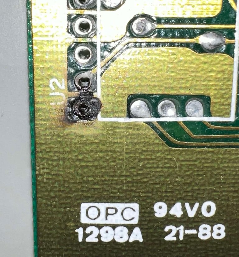
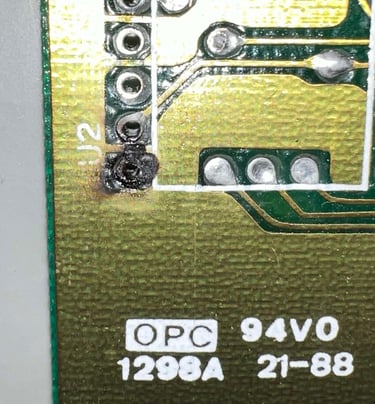
Both pin #19 (TOD) and pin #20 (+5V) are extremely close to the GND plane on the PCB. And I did install a socket for the CIA#2 at some point, but what seems to have happened is that some small area of the GND plane has not been coated. And then some flux residue (?), or tiny amount of solder, from the socket (on pin #20) has reached the GND plane. Note that there was not a dead short between GND and VCC. The short only occured when power-on.
In the picture below you can see where the short circuit was. And also, you can see how close the VCC is to the GND plane on the PCB. Is this really a good PCB design?
After fixing the short circuit the resistance between +5V and GND is back to about 500 Ohms.

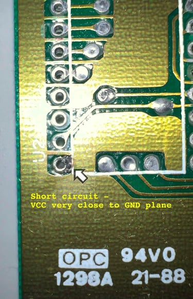
The picture above was taken after cleaning. Below is a picture taken after the socket was removed. Notice that the area surround GND, VCC and TOD (pin#19) are all part of the short circuit. Could this also be the reason for the Time of Day (TOD) clock behaving weird?
Bad color RAM (?) - how to fix a problem without fixing it...
NOTE: In the following the CIA#2, Character ROM and BASIC/KERNAL ROM are all removed.
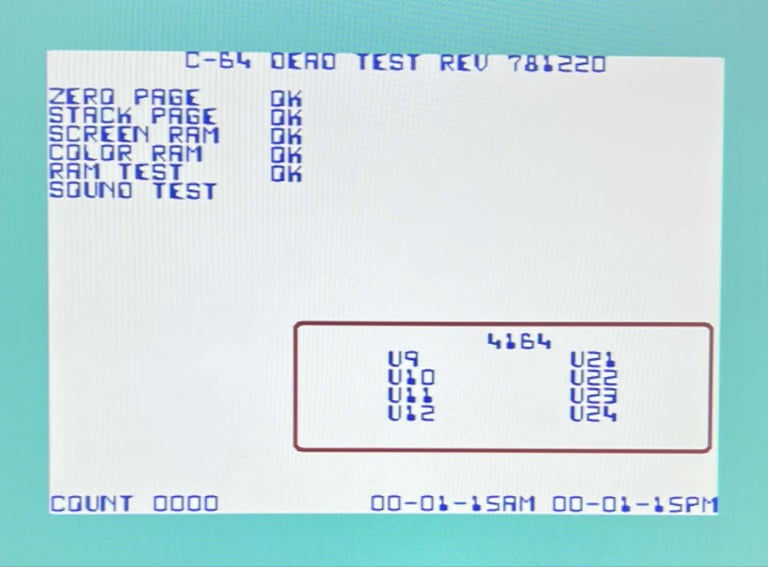
This C64C is full of surprises... When booting the machine with the Dead Test Cartridge after the short circuit repair I get a "COLOR RAM: BAD" fault.
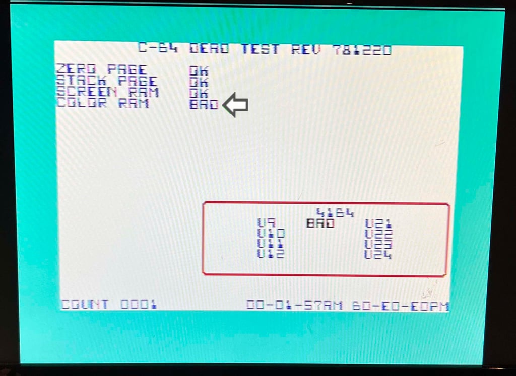

Notice that the Dead Test Cartridge also reports "4164 (U9-RAM)" as BAD. But this fault message is not really accurate for the C64C as it does not have eight 4164 RAM ICs. One other thing I notice during the testing with the Dead Test Cartridge is that "COLOR RAM: BAD" is not always triggered. There I identify three different fault reports:
COLOR RAM: BAD immediately when test begins. The square area surrounding the 4164s is RED.
COLOR RAM: BAD after about halfway in the test. The square area surrounding the 4164s is RED.
COLOR RAM: OK. The square area surround the 4164s is BLACK.
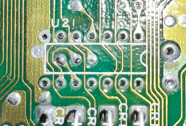
My hypothesis is that this is caused by a marginal CMOS 4066 (U21). This is an analog switch which enables/disables the four data lines from/to the color RAM IC to connect to the rest of the data bus. Before desoldering the 4066 all the solderpoints are resoldered - just to make sure that it is not caused by a bad connection. But resoldering the points does not improve on the situation.
The 4066 analog switch is desoldered from U21 without any damage to pads or traces.
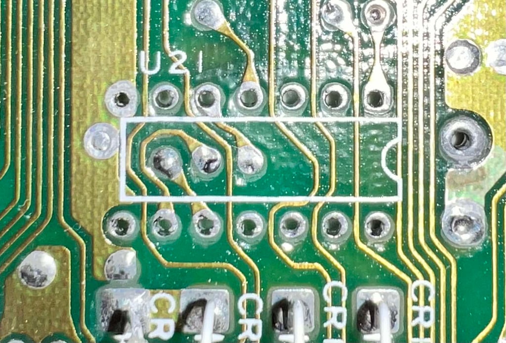
It turns out that changing the 4066 does not improve the situation...
Is there something fishy with the CS line on CIA #1 (?)
Its been quite some time since I worked on this machine. But that is sometimes a good thing. Taking a step back to think. During the re-vitalisation of this fault finding process the following has been done:
A missing trace from the CPU on D0 to the left RAM IC (U10) was identified and fixed with a bodge wire
The MOS 8500 was desoldered and tested. A new IC socket installed (the CPU turned out to be working fine)
The MOS 6526 CIA #1 was desoldered and tested. A new IC socket installed (and two bodge wires installed - sorry I ripped a few pads)
Now, why on earth choose to desolder CIA #1 (?). Well, for some reasons I am struggling to understand the CIA #1 was acting weird when returning to the fault finding process. When the Dead Test cartridge runs the TOD clock for U1 is wrong, and in addition the dead test program crashes from time to time.
After quite some time checking with the oscilloscope I find something which might point me to the problem:
The CS line on PIN #23 is constantly LOW (with some little noise). That implies that the CIA #1 is constantly activated, which is not correct. The PLA should only pull the CS line LOW when the CPU is requesting data in the $DC00 address range.
The CS line on PIN #23 (CIA #1) is directly connected to the PLA on PIN #34. Could the PLA be marginal?
Desoldering the PLA
As the PLA is directly connected to CIA #1 on the CS line I choose to desolder the PLA. The PLA are not common to fail, but I wonder if this one actually do fail. Desoldering the 64 pin PLA on a short board is not trivial. But I manage to desolder it "quite ok, but some of the pads on the backside did come off. I really do think that this board is very fragile when it comes to desoldering. The temperature on the desoldering gun is set to only 330 degrees Celcius, but still the pads fall off. Below is a picture of the desoldered area on the top side of the PCB.
A new machine pin socket is installed and the PLA is re-inserted to verify nothing broke during the operation. But then something weird happens... this is the machine that just keep on giving! Now I see - and hear - a lot of analog noise when running the Dead Test cartridge. The machine also crashes from time to time, but this is really weird. But the thing is that this fault looks quite a lot of the first original fault I saw very early in the repair process. What on earth is happening?
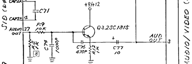
There is a clue: the audio noise. There are no SID chip installed during repair, but still I can hear this weird buzzing noise. Why? In the schematics below you can see the circuitry of from the analog audio output of the SID which is fed to the 8 pin DIN connector.
And now the mystery continues... I choose to desolder transistor Q3. And while the transistor is removed from the PCB the machine is turned on with the Dead Test. And lo-and-behold the noise is gone (!). But... when testing the diode junctions of the transistor with a multimeter they measure just fine. The transistor can still be faulty, but this is getting really weird...
A "new" Super PLA is ordered from Retroleum.co.uk and installed in the machine.
With the new Super PLA in place the CS line on pin 34 (on the PLA) is now back to normal! This is good! The signal is HIGH almost all the time, the only exception is when the CIA #1 chip is requested from any code.

Does this fix the CIA #1 problem? Yes! It does! Also, it looks like the Q3 transistor "fault" was a red herring. I am not sure why, but the weird noise is now gone. Maybe just a bad power connection. Below is a picture of the machine running the Dead Test cartridge. Things looks normal.
New sockets for the character ROM and the Kernal/BASIC ROM are soldered back to the board. And the the ROMS are installed. And voila! The machine is now booting up (again).
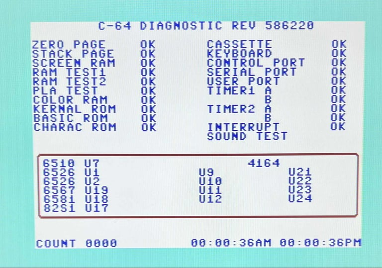
As a quick test the Diagnostics cartridge (with harness) is installed. And as can be seen from the pictures below all test pass with flying colours.

The RF-modulator is re-installed without any issues. Below are some pictures of the mainboard after repair.
Even if the original reset (push-button) was repaired a new push-button is installed. The old one was working, but it didn´t quite feel right when the button was pressed.
UPDATE: During testing it was discovered that quite a few connections on CIA #1, CIA #2, Kernal, Char ROM and the PLA were poor. So bodge wires were soldered in to fix these issues.
Testing
Proof is in the pudding - does it work?
Testing is done through three main stages:
Testing the basic functionality and chips
Testing the complete set of custom ICs and I/O ports
Testing by using the machine playing demos, games etc. accessed by both floppy and datasette to verify correct operation
NOTE: Some of the colours are "off" due to a poor LCD monitor used for the pictures. All colours are correct, but they do not appear correct in the pictures.
Basic functionality and chips
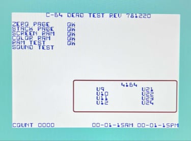
First test is done using the Dead Test Cartridge. This test doesn´t test all the functionality of the Commodore 64, but it does test the basic functionality of the major chips such as the CIA #1/2, CPU, VIC-II, PLA, RAM and SID. As the picture shows below the test is passed.
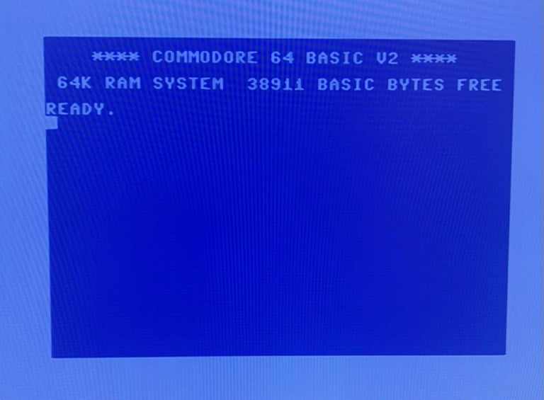
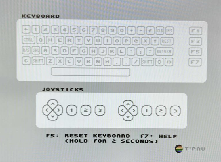
Next test is to power the Commodore 64 to the blue boot up screen (and the JiffyDOS), and also check the keyboard to make sure all keys works as they should. The test is passed; all keys works and 38911 BASIC Bytes Free.

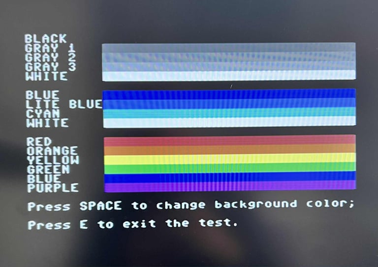
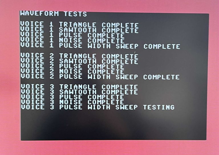
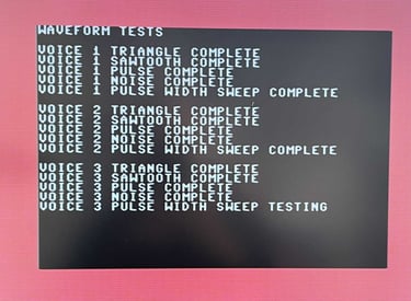
The basic functions of the VIC-II and SID is tested with 64 Doctor, and Commodore 64 SID tester. Note that this is to be considered as basic functionality - more advanced (?) functionality such as sprite handling / collision detection / advanced audio will be tested later.

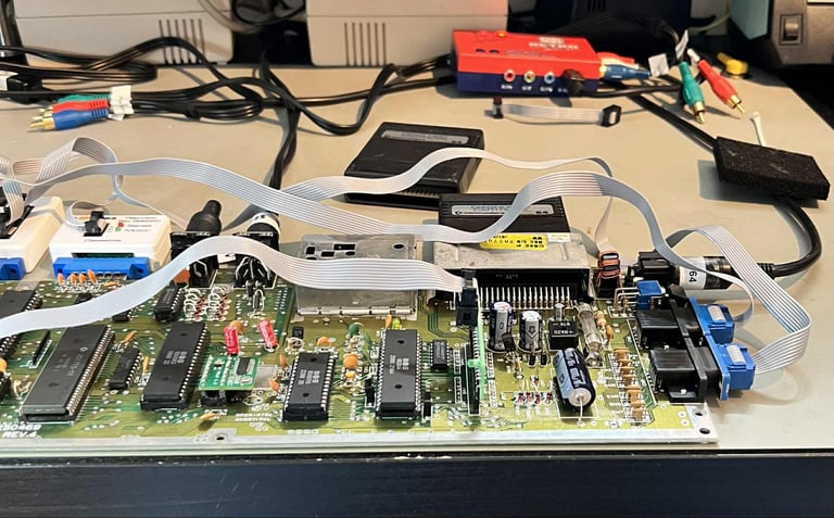
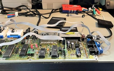
Diagnostics test with harness
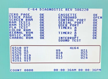
To test all the custom ICs, and I/O ports, the Diagnostics cartridge is used. The Diagnostics cartridge is very valuable when the complete test harness i installed as in "everything" is tested formally. As can be seen from the picture below, no issues are identified.

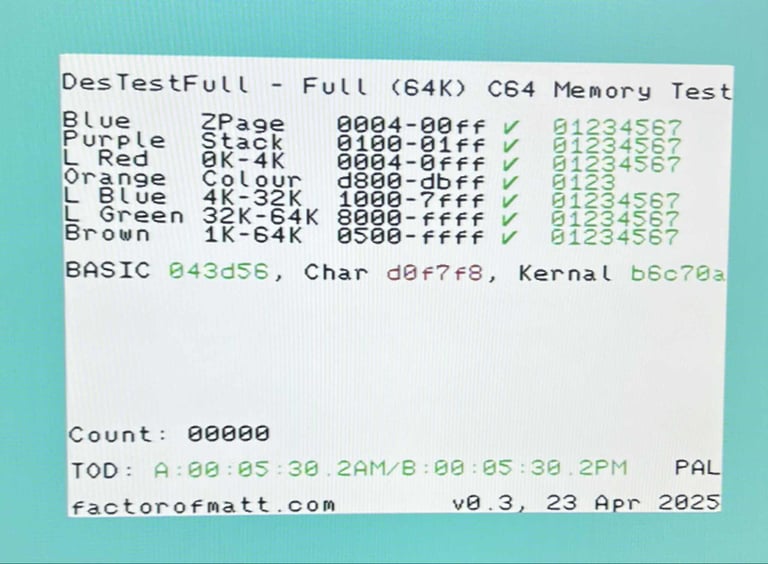
Testing the full 64k of RAM
To make sure that all the 64k of RAM is fully working the DesTestFull cartridge is used. This software use the March-B algorithm to test all the RAM extensively. No issues are identified.

Extended testing
Knowing that the basic functionality of the machine works the testing continues by using the Commodore 64 for normal operations; playing some games, watching demos, loading from datasette and floppy and using a cartridge. This task is will be performed by the owner - and if any issue is detected I will try to fix it.
Final result
"A picture worth a thousand words"
Below is a collection of the final result from the refurbishment of this C64C. Hope you like it! Click to enlarge!
