

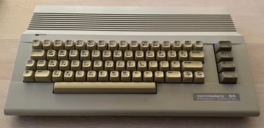
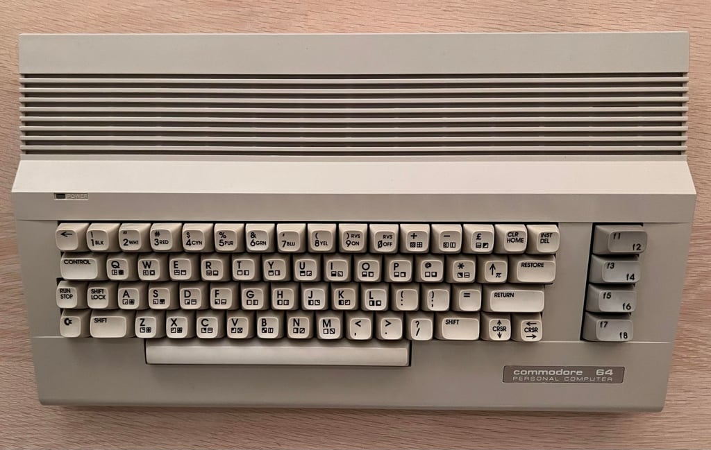
C64C
Ser. No. 1281026
Assy 250469
Artwork 252311 (REV A)
Starting point
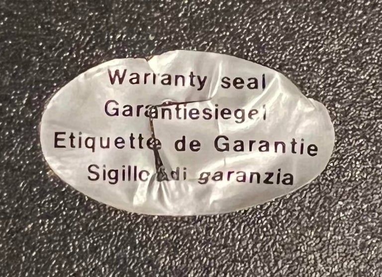
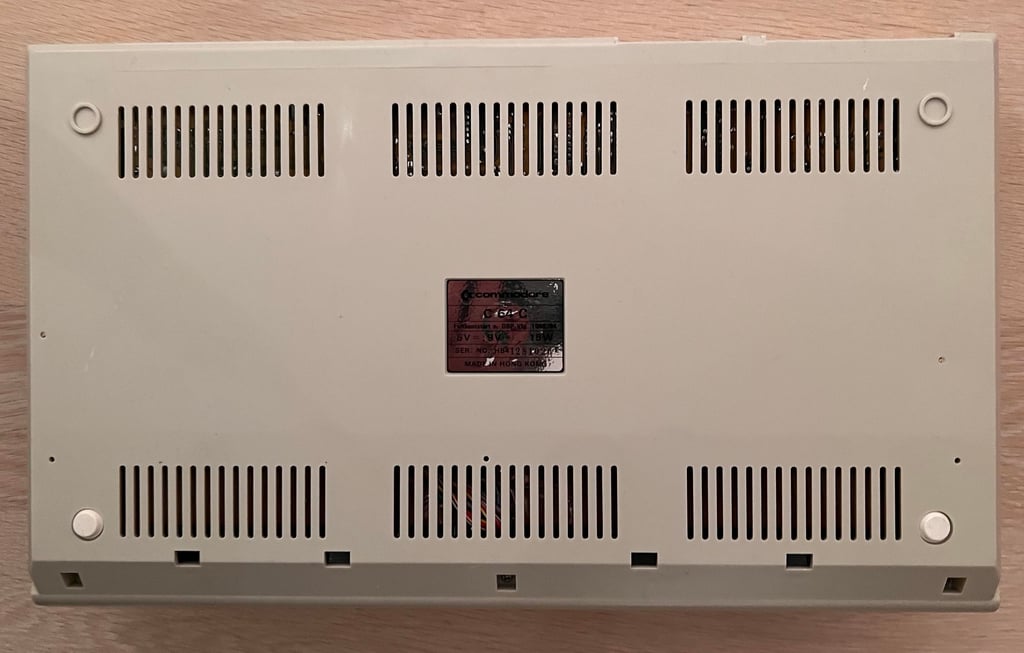
First thing I notice is that this machine has never been opened since it was produced probably sometime in the late 80s: the warranty seal is not broken. That said, I don´t know if it works or not, but I will figure that out later.
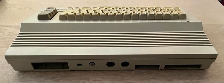
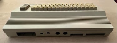
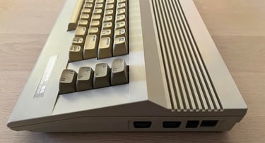
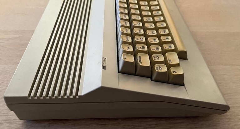
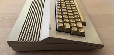
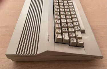
The keyboard is quite yellowed, but the machine looks otherwise fine. I can not see any visual damage to it or feel any broken parts/keys. It is very dirty. The pictures lie quite a bit. There are more grease and dirt on the machine than meets the eye from the pictures.


Refurbishment plan
To refurbish this C64C the plan is to do this trough the following steps (some of them in parallell):
Clean and remove stains from the exterior casing
Clean and restore the keyboard
Retrobright casing and keycaps
Refurbish mainboard (cleaning, checking, repairing, replacing capacitors and voltage regulators, adding heat sinks etc.)
Recap RF-modulator
Verify operation by testing
Exterior casing
Not a big deal, but I try to preserve the warranty seal as good as I can. By applying some hot air from a hair dryer I try to peel the sticker off with a sharp knife. It is not perfect, but I am quite satisfied with the result. The seal breaks a bit around the square hole where the screw is, but that is ok. The warranty sticker will be glued back as a final touch of the refurbishment.

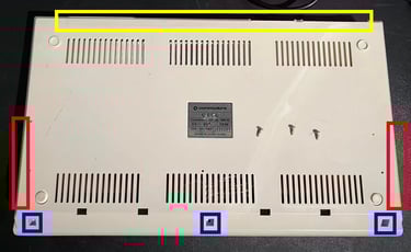
To separate the top- and bottom cover the three Phillips screws at the bottom are removed (blue squares). Then I use my fingers to gently press the sides to that the interior clips let go (red squares). Also, there are some interior clips on the back of the top/bottom cover. With some careful wiggling the top- and bottom cover get separated.
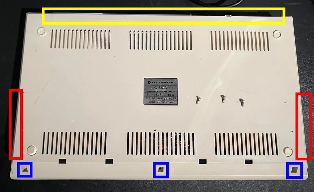
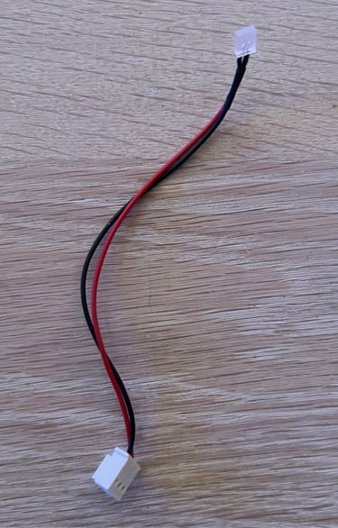
When opening the top cover the inside is exposed. Note: it is wise to remove the LED wire (yellow square) immediately so that it isn´t damaged. The inside looks ok at first glance - but holy moly - there is a lot of dust inside here.
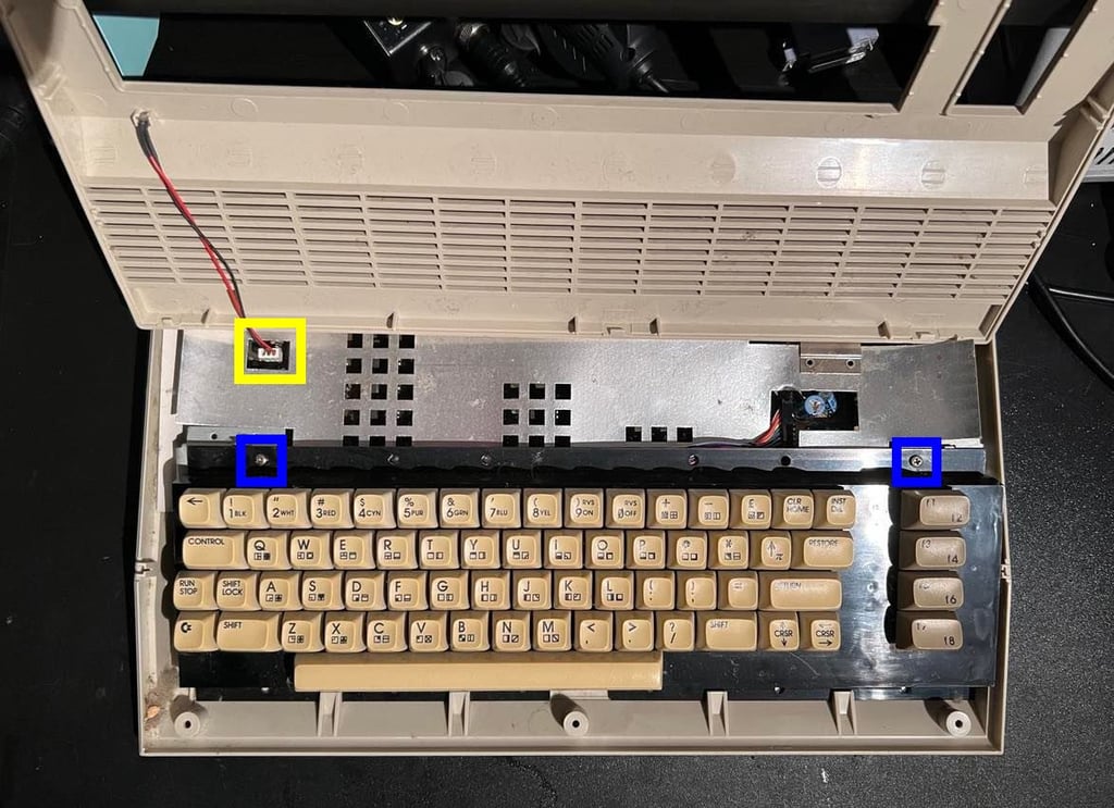
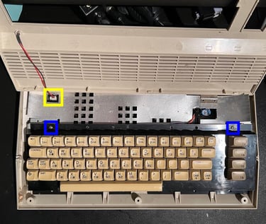
Next, the two screws holding the keyboard is removed (blue squares). The keyboard is lifted partially and the connector is removed (yellow square picture below).

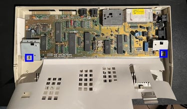
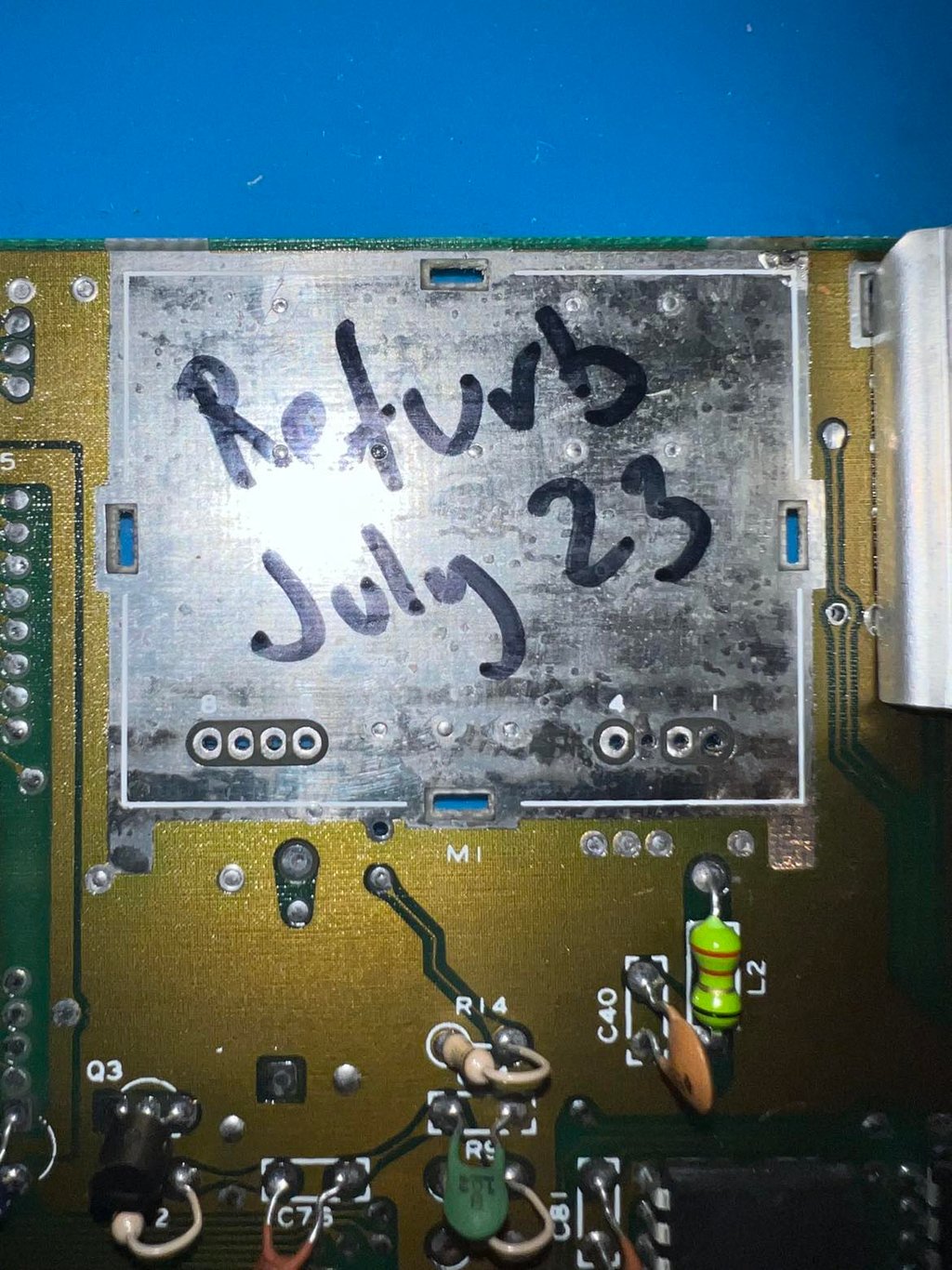
When the cardboard shield is lifted the interior is exposed. Probably never seen the light of day for the last 34 years or more... The PCB is full of dust, but at first glance it looks ok!
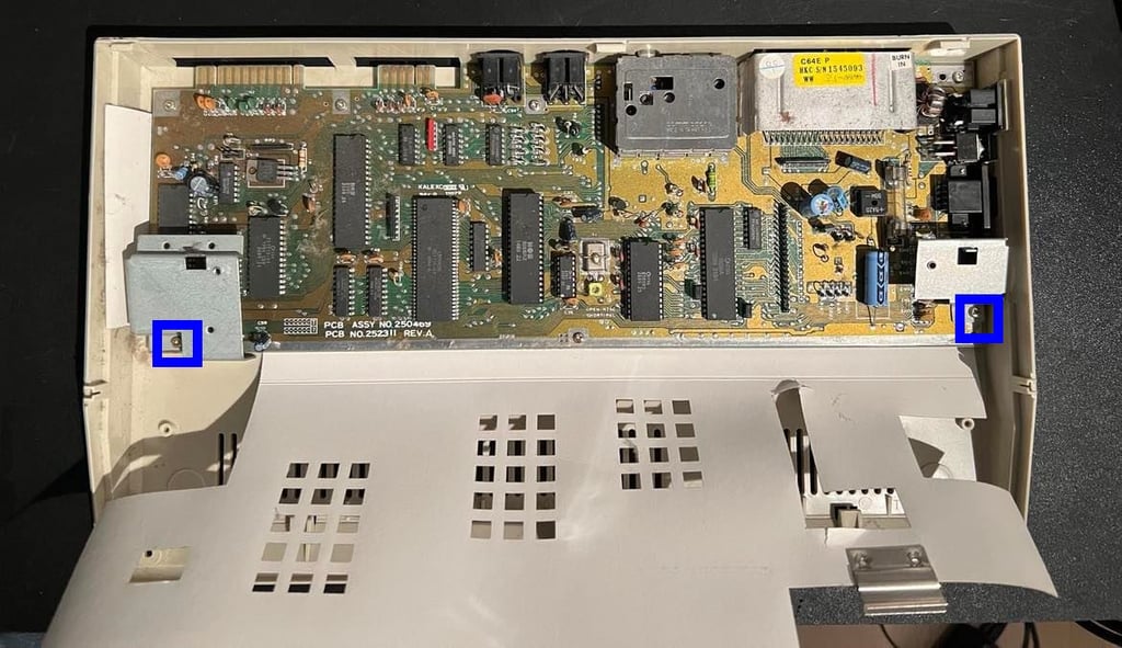
There are two metal brackets used as keyboard standoffs. These are removed (screws in blue squares) - note that these two screws are a bit longer than the rest of the PCB screws so it is smart to keep these separated. The remaining screws are removed and the PCB is lifted out of the bottom cover.
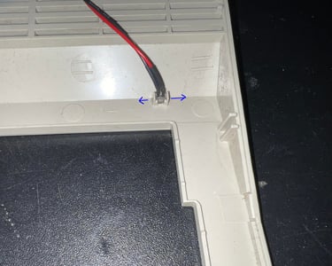
Before cleaning the top- and bottom cover the LED is removed. By gently pushing the two plastic clips in opposite direction while pulling the LED it is lifted. Note that the plastic is old and brittle so it is a good idea to be extra careful and patient so that it does not break.

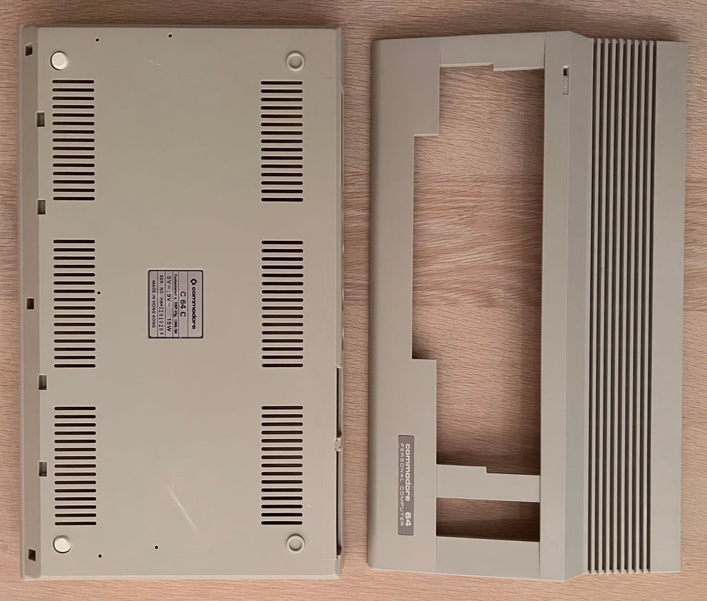
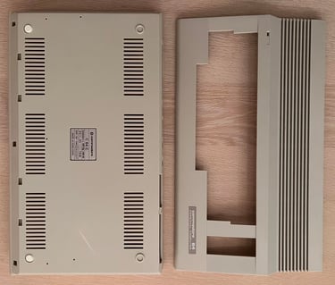
Both the top- and bottom cover is first rinsed with mild soap water. Then both parts are cleaned with isopropanol and glass cleaning spray. Even if the casing it not very yellowed it is retrobrighted after the cleaning. Since the keyboard will be retrobrighted I will be good to have both as “new looking” as possible.

The result after both cleaning and retrobrighting is very satisfying. Below is a picture of the top- and bottom cover after this process.
Keyboard
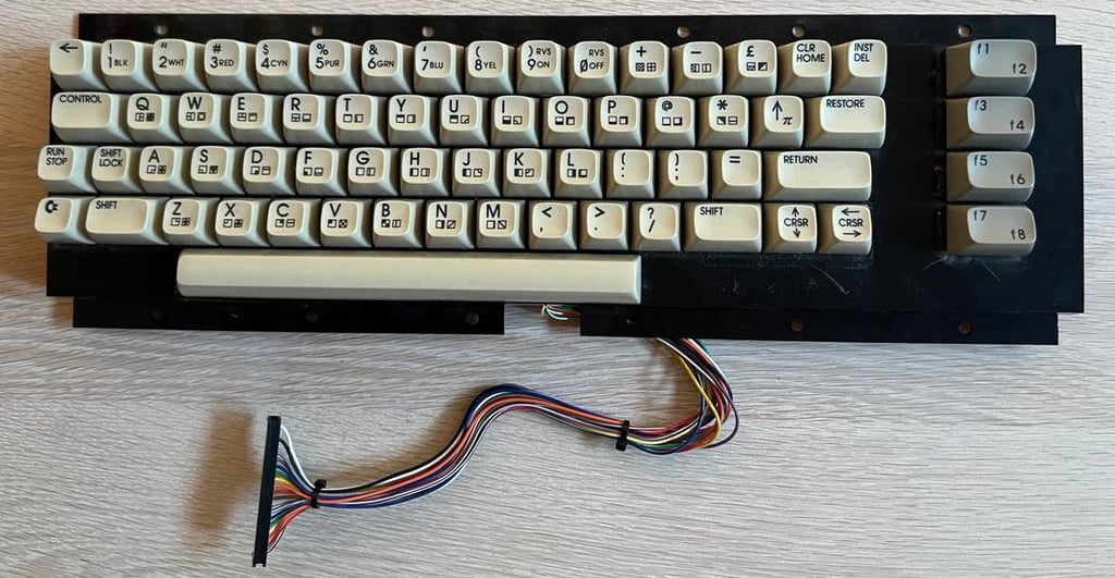
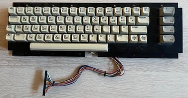
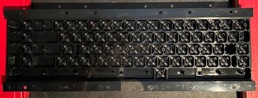
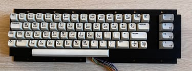
The keyboard seems to be in good condition. It is quite yellowed, dirty and full of dust - but otherwise it looks to be intact. See picture below.
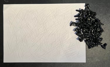
All the keycaps are removed with a keycap puller. This is a gentle way of removing them, both preventing the plungers to break and prevents damaging the keycaps. This process also reveals the dust and dirt beneath the keys.
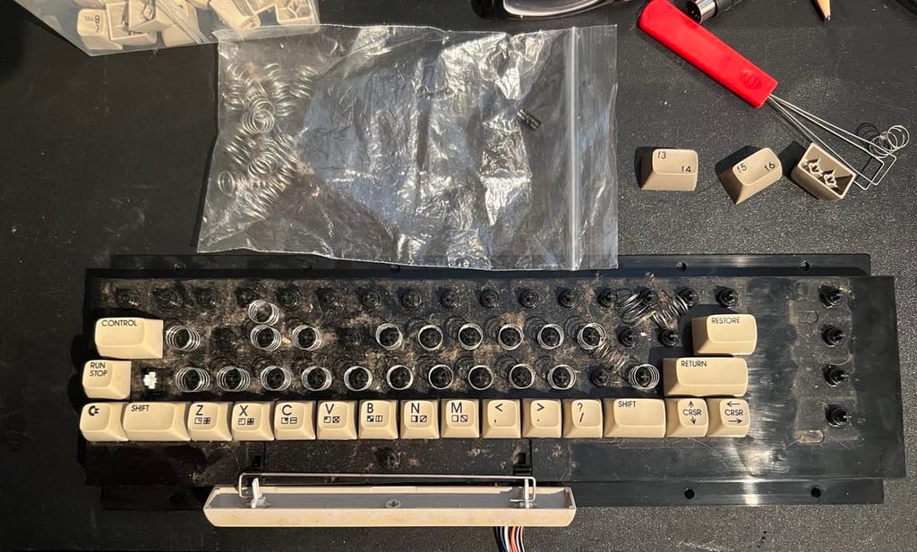

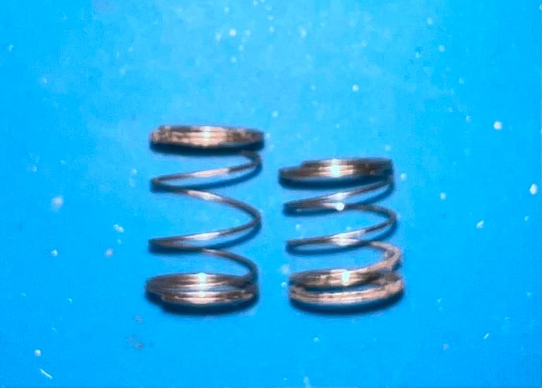
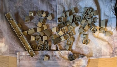
Note that the spring used for the spacebar is bigger than the rest of the springs. So it is a good idea to keep this spring in a separate bag. In the picture below the two spring types are shown. All the keycaps are placed in a box with water and dishwasher soap for about 12 h.

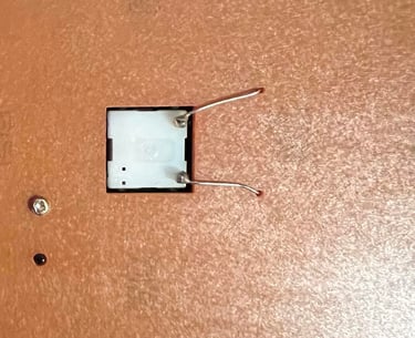
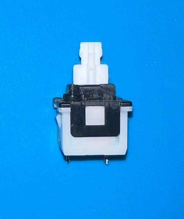
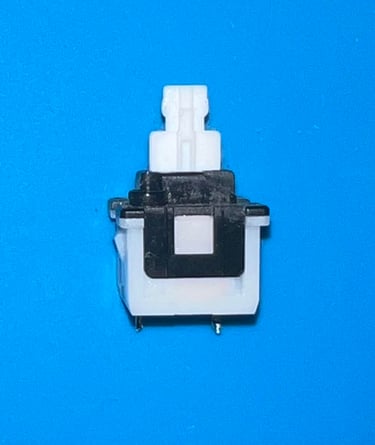
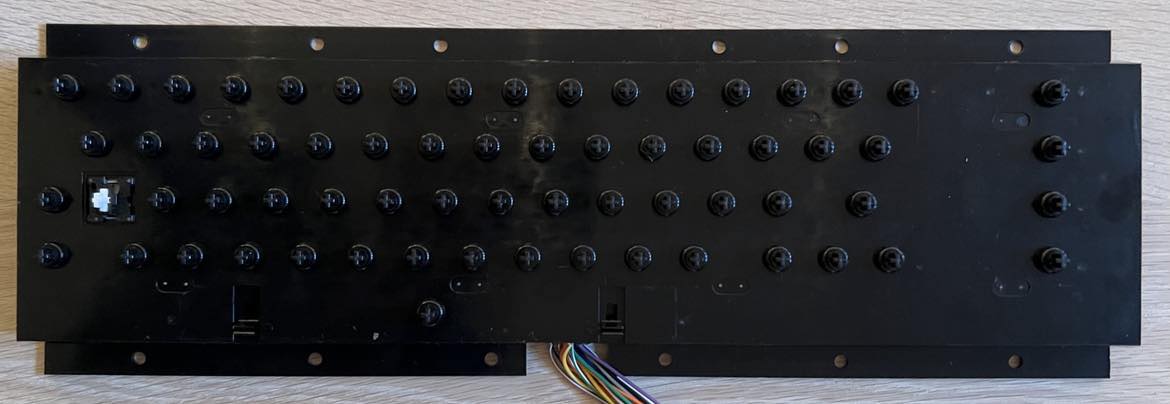
The SHIFT LOCK key is removed by first desoldering the two wires from the backside of the keyboard. Then the SHIFT LOCK key is pushed firmly from the backside towards the frontside. The key will "pop out" quite easily. Below are pictures before desoldering the wires and the SHIFT LOCK key removed.

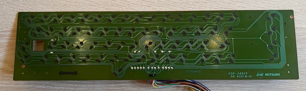
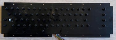
All the small screws in the backside are removed. Then the PCB is lifted out. This PCB is a MITSUMI KSR-A66YF model which is a quite common version. It is cleaned carefully with some isopropanol on a paper towel. It is important to be careful when cleaning so that none of the carbon pads are damaged. Picture below shows the PCB after cleaning.

The keys looks way better after cleaning, but they still needs some retrobrighting. Picture below is taken while the keys are drying up after cleaning.

To revive all the plungers I carefully swipe the ends on a piece of paper. This will remove dust and grease in a gentle way. If this is not sufficent I will need to clean with isopropanol later, but I will try this first. From experience I find this way both the most gentle and efficient way to revive the plungers.

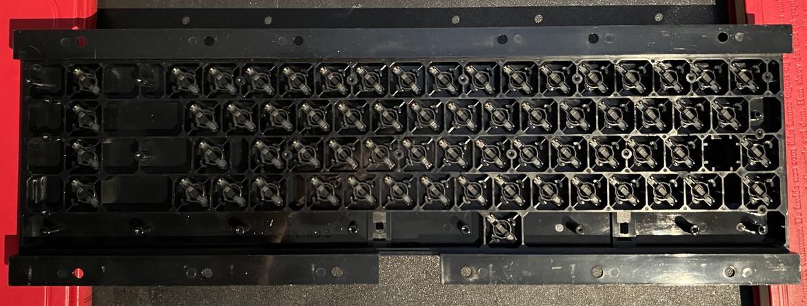
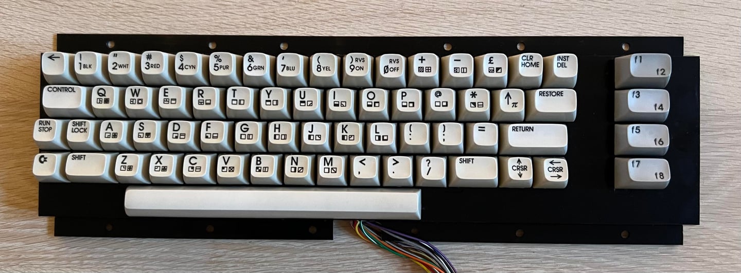
All plungers and the SHIFT-LOCK is put back in the cleaned plastic bracket. As the pictures show below they keyboard chassis and plungers looks good as new.
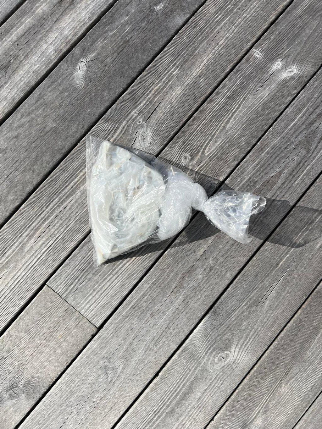
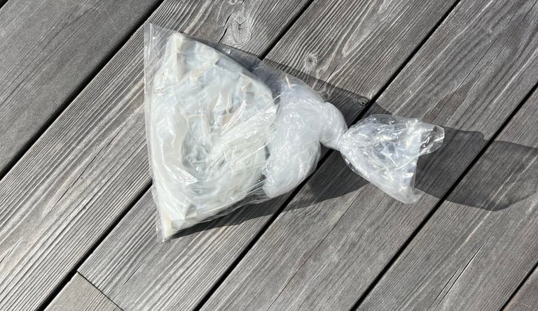
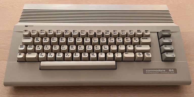
The keys are quite yellowed so I go for some retrobright. All keycaps are placed in a plastic bag which is filled with some 12 % hydroperoxid cream - and left for a whole week (!). The plastic bag is primarily kept inside with normal room temperature (and no UV), but occasionally placed outside when the weather is nice. I am very happy with the result! The keys looks way better after this retrobright. See pictures below.
Mainboard
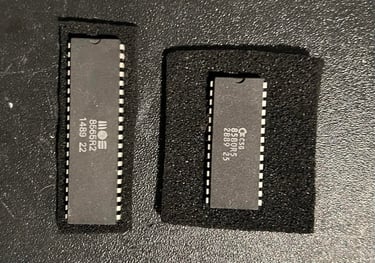
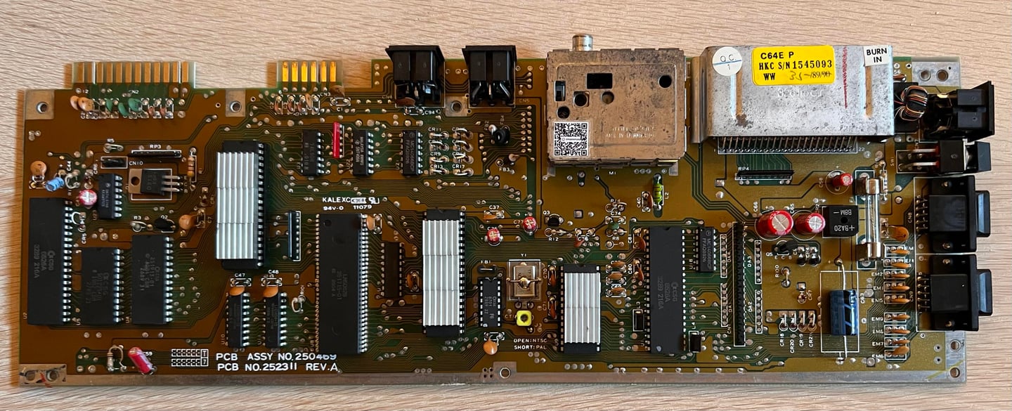
This is the "C64E" mainboard AKA "the shortboard" which is thinner compared to older C64 mainboards (AKA "longboards"). The reason Commodore managed to make a smaller PCB was because several of the components are now combined; from 8 to 2 RAM chips, PLA/logic chips/(Color RAM) integrated into one chip and Kernal and BASIC combined in one chip instead of two separate.
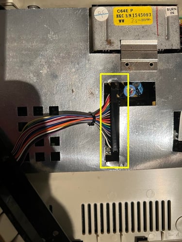
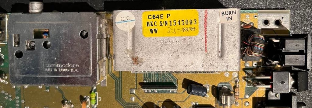
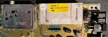
On the cartridge port there is an interesting label saying "C64E", "HKC", a serial number and "35-89". My guess is that this means that this Commodore 64 was assembled in week 35 in 1989 in Hong Kong which is 27th August to 1st September 1989. Wow! Could it mean that? If so, that is so cool!
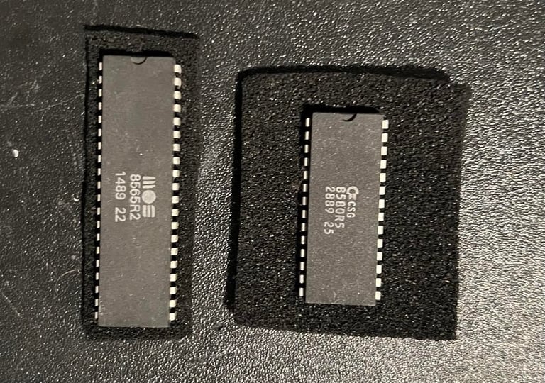
But... before I continue to inspect the mainboard I clean it. It is so full of dust and grease that I simply don´t stand the idea of working with it in this condition. To clean it first remove the SID- and VIC-II chip and - lo and behold - wash it with plenty of water and mild soap. Yes, I can hear you cry out in tears, but this is no problem if you let it dry completely afterwards. Also use plenty of isopropanol to make the water evaporate.
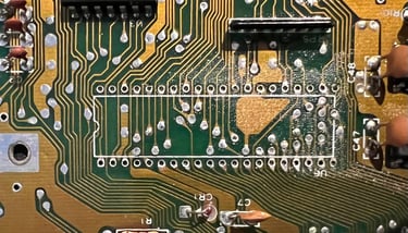
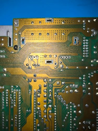
The result of the cleaning is quite good. It will be cleaned further with isopropanol as I progress, but now it is in a satisfying condition for refurbishment. Below are pictures of the front and back of the mainboard after cleaning (the VIC-II is put back in, but I wait with the SID chip since this is not required for the C64 to boot).


Visual inspection
As previously mentioned this is a C64E mainboard, more specific; Assy 250469 Artwork 252311 REV A. The board looks to be in very good condition (after cleaning). I can not see any sign of corrosion or damage of any kind.
Below is a list of all the main chips on the mainboard:
A helping hand
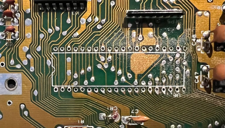
When repairing another C64C I used this mainboard to test a MOS 8500 CPU. Therefore I desoldered the CPU on this mainboard and installed a socket. It is not trivial do desolder on this mainboard, but it went ok and no pads or traces were lifted.
Checking the voltages
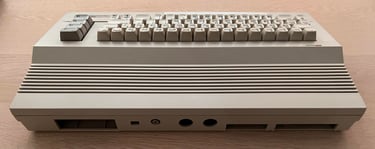
... and resistance I should say. I think it is good practice to measure that there is no short circuit connecting the 5 V DC and 9 V AC from the power supply (PSU). It is easy to the find the place to measure these at the User Port (see my article Checking C64 Voltages for details). Luckily, there are no short circuit here so it should be safe to power the C64C on.
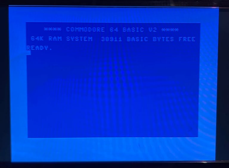
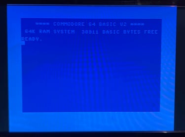
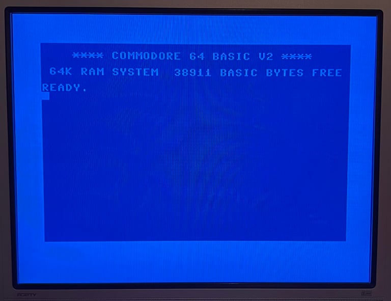
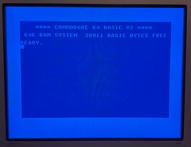
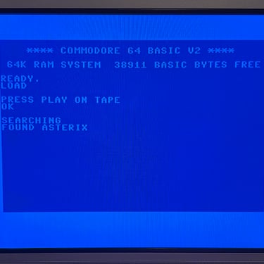
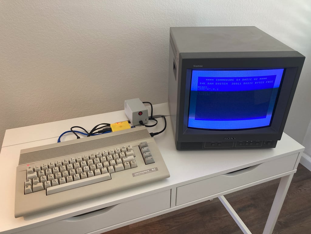
When powering on a familiar screen appear on the screen; the classic blue Commodore 64 screen with 38911 BASIC BYTES FREE. Perfect! That doesn´t mean that the machine is without faults, but at least it boots up.
All voltages are measured ok which is good - see table below. They will be measured again after refurbishment, but the voltage levels as they are now should at least not make any problems
Replacing the electrolytic capacitors on the main board
This machine is over 30 years old, and the electrolytic capacitors are prone to dry out. It is not common that a Commodore 64 is faulty due to not-correct capacitance and/or ESR values, but you can experience odd behavior. Therefore it is good practice to replace the electrolytic capacitors on the mainboard.
New quality capacitors are used and the different values are found in the capacitor list library. Below is a picture of the mainboard after new capacitors are installed.


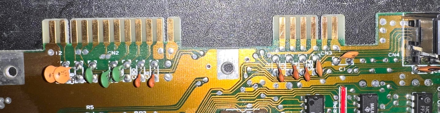
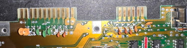
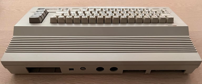
Cleaning the user- and datasette port
A very simple operation, but with a great effect. After many years the user- and datasette port are dirty and oxidized. If this is not properly cleaned using peripherals such as datasette may not work as expected. To clean the user- and datasette port a normal rubber eraser is used carefully to remove most of the grease. While doing this you will see the copper is revived back to its original color. Finally the port connectors are cleaned with isopropanol on a Q-tip.
See picture below of the cleaned user- and datasette port connectors.
Adding heat sinks to custom MOS chips
Cooling is essential if a chip is to last long. The C64C is running much cooler compared to the C64 breadbin model, but it is still good practice to add heat sinks to the most crucial (and hot) ICs; the MOS 8500 (CPU), MOS 8580 (SID) and MOS 8585 (VIC-II).
Most of the heat dissipation is through the IC pins to the mainboard, but the heat sinks will improve the dissipation of heat to the surrounding air. In effect this will cause the ICs to maintain a lower temperature when the machine is in operation – increasing the probability for the ICs to last longer.
Below is a picture of the mainboard with the heat sinks installed.

RF-modulator
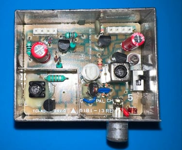
The RF-modulator is of type 251916-03 which contains three electrolytic capacitors according to the capacitor list. Although not strictly required I think it is good practice to replace these with new modern capacitors. But this requires the RF-modulator to be desoldered which is not trivial. It is by no mean impossible, but special care is necessary to avoid damage either to the mainboard PCB or the RF-modulator. I do this by using the technique described in this HOWTO article.
No trace or pads were damaged during the desoldering process. See pictures below.


For some reason there are only two electrolytic capacitors - instead of three which I expected. So there are obviously some versions of the 251916-03 which does not use the 100 uF. In this RF-modulator only the 220 uF [10 V] and 10 uF [16 V] were used. These are replaced with quality capacitors from Wurth Electronics.

Proof is in the pudding - does it work?
Testing is done through two main stages:
Testing the basic functionality and chips
Testing by using the machine playing demos, games etc. accessed by both floppy and datasette to verify correct operation
Basic functionality and chips
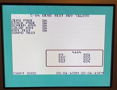
First test is done using the Dead Test Cartridge. This test doesn´t test all the functionality of the Commodore 64, but it does test the basic functionality of the major chips such as the CIA #1/2, CPU, VIC-II, PLA, RAM and SID. As the picture shows below the test is passed.
Testing

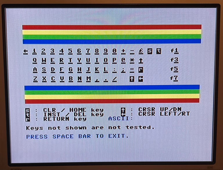
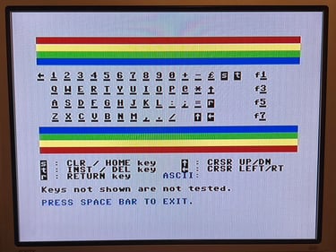
Next test is to power the Commodore 64 to the blue boot up screen and also check the keyboard to make sure all keys works as they should. The test is passed; all keys works and 38911 BASIC Bytes Free.
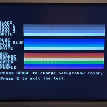
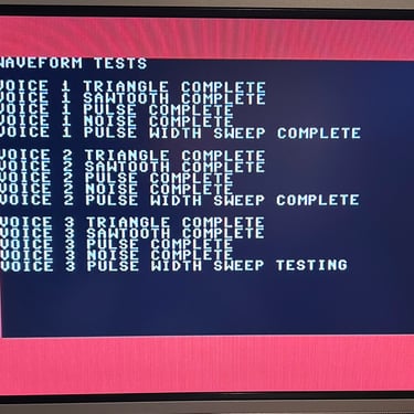
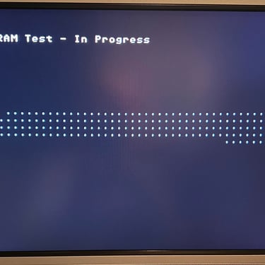
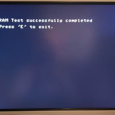
The basic functions of the VIC-II, SID and RAM is tested with 64 Doctor. Note that this is to be considered as basic functionality - more advanced (?) functionality such as sprite handling / collision detection / advanced audio will be tested later. But the basic tests pass without any detected faults (click to enlarge).
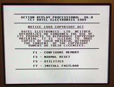
Last basic check before moving to more extensive testing is checking the cartridge. This is done by using the Action Replay VI. Result is that the test is passed.

Extended testing
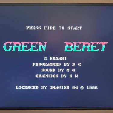
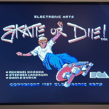
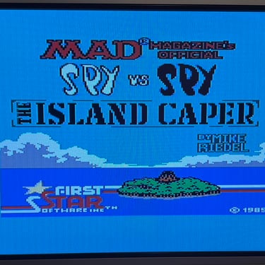
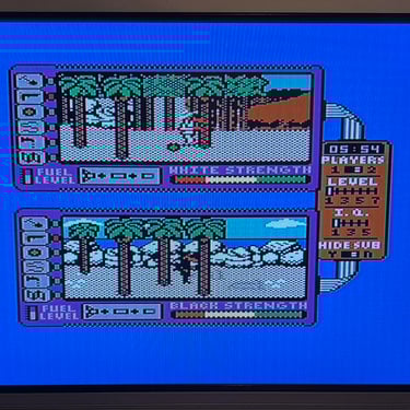
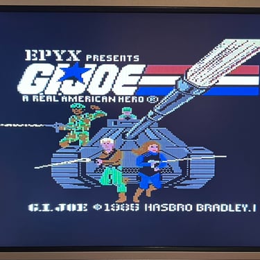
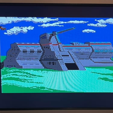
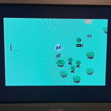
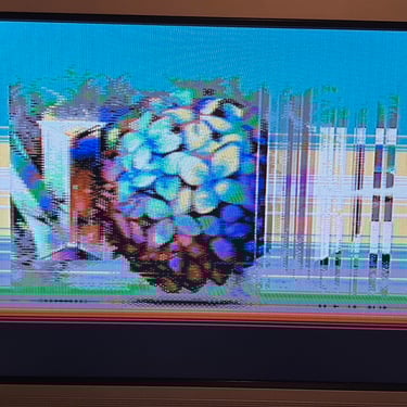
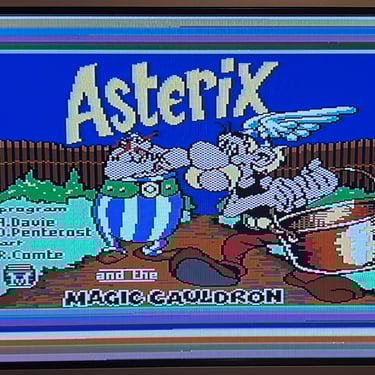
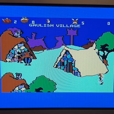
Knowing that the basic functionality of the machine works I continue the testing by using the Commodore 64 for normal operations; playing some games, watching demos, loading from datasette and floppy and using a cartridge. I can not find any issues with this machine. I also pay special attention to the video to make sure that there are no glitches in the graphics - I can´t see any abnormalities. Below is a gallery with pictures from the testing.


Final result
"A picture worth a thousand words"
Below is a collection of the final result from the refurbishment of this C64C. Hope you like it! Click to enlarge!


"Are you keeping up with the Commodore? 'Cause the Commodore is keepin up with you!"
Below are some pictures of the Commodore 64 back at the customer´s home!
