

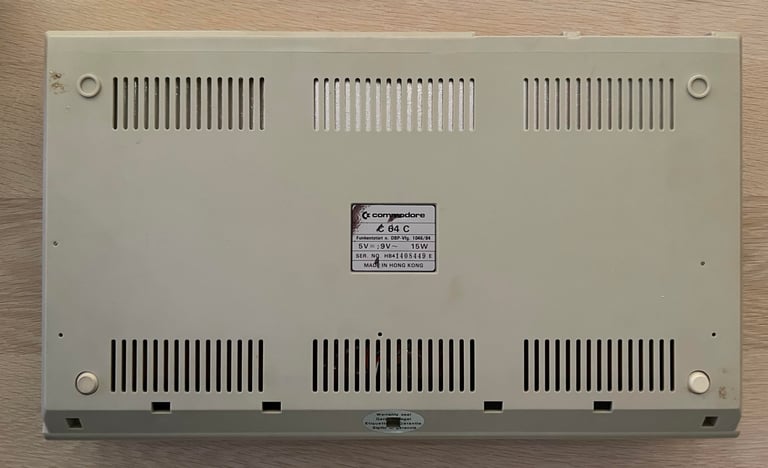
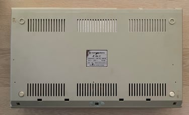
C64C
Ser. No. 1408449
Assy 250469
Artwork 252311 (REV A)
Starting point
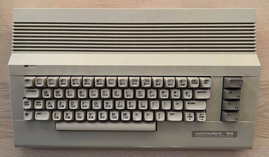
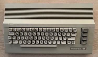
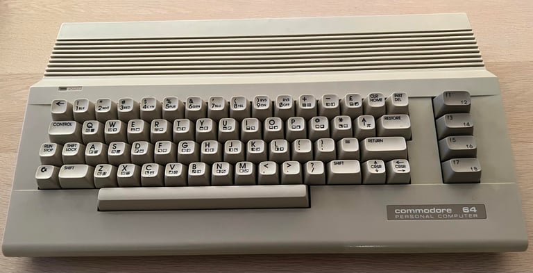
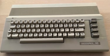
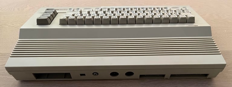
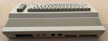
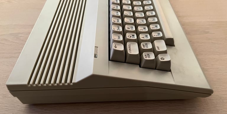
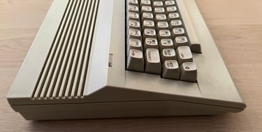
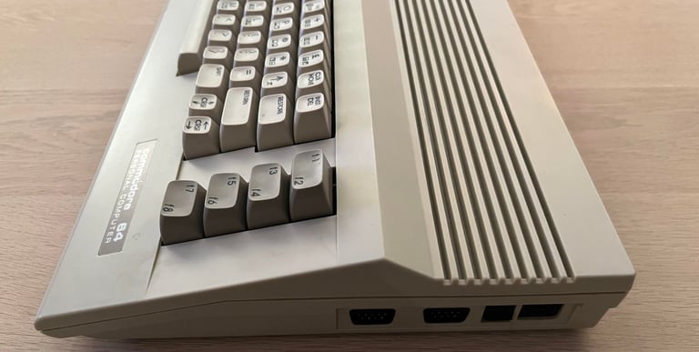
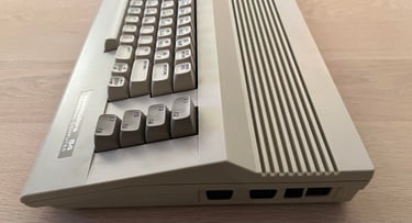
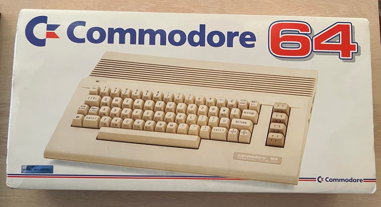
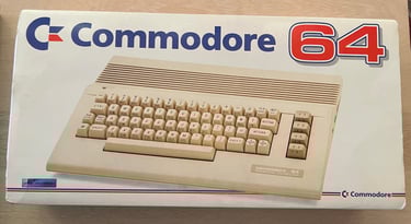
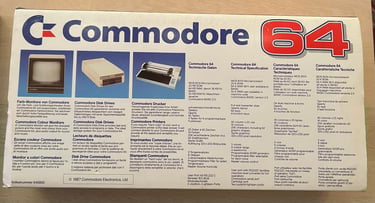
This very good looking Commodore 64C has come to me for repair. So the plan is not to do a full refurbishment of this one, but to only repair the mainboard. Below are some pictures of the machine. As mentioned it looks very good from the outside - and it is very cool to see that the box is in very good condition. This is a lucky owner.

Refurbishment plan
This will not be a full refurbish of a C64C, but a repair. The plan is to:
Repair mainboard
Verify operation by testing
Opening it up...
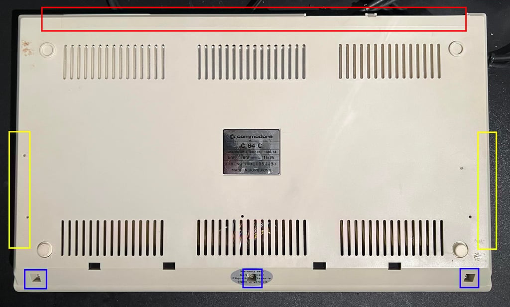
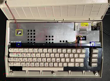
It may come as a surprise, but to repair the mainboard I need to open the machine... :-) To do that I first remove the three Phillips screws at the bottom (blue squares), push gently on the sides (yellow squares) while wiggling the back side hinges (red squares).

This will reveal the inside of the machine, but the RF-carboard shield is hiding the mainboard. Next the LED wire is removed (yellow square), the keyboard screws (blue squares) and the keyboard connector (red square).
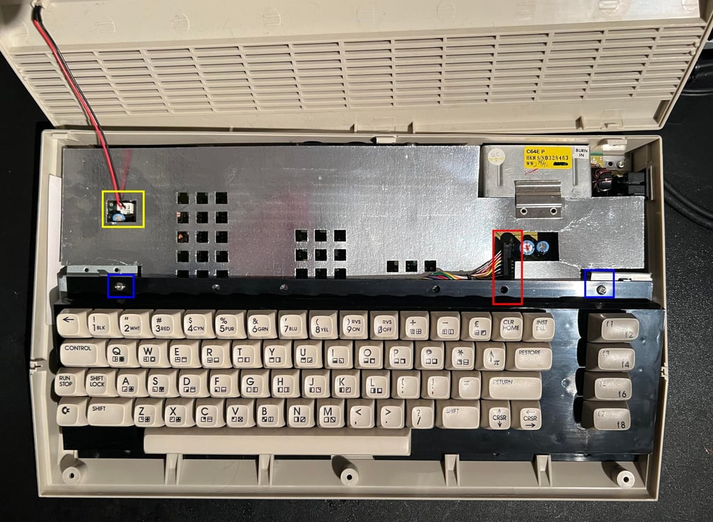
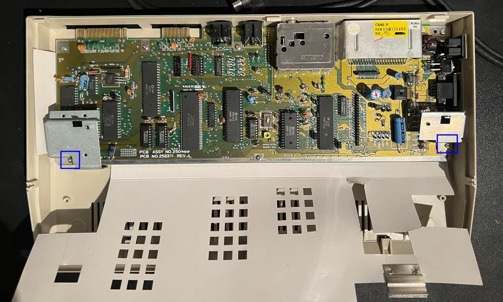
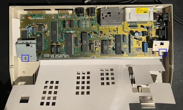
When the keyboard and RF-shield is out the way the mainboard is exposed. I will check it in detail but it looks to be in very good condition. To remove it out of the bottom case the screws are removed. Note that the keyboard stand-offs have longer screws - so it wise to keep these separately (blue squares).
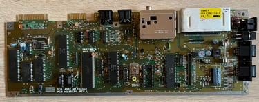
Mainboard
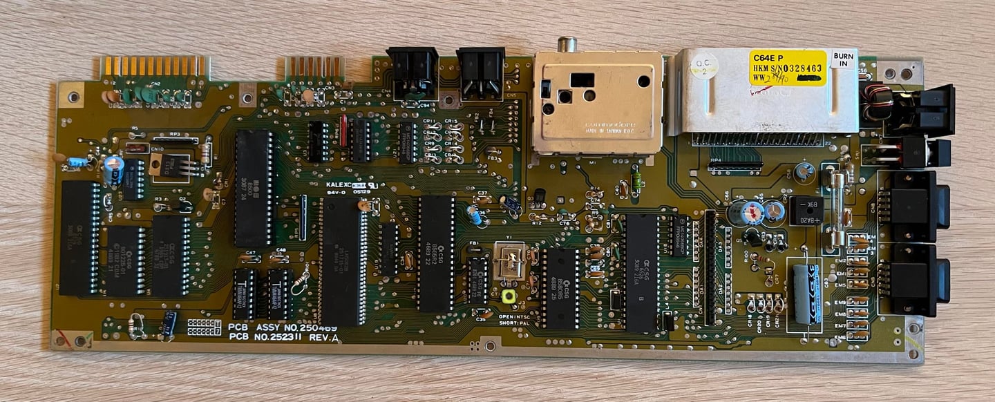
This is a C64E PCB (aka "shortboard") - assy 250469 artwork 252311 (Rev A). Compared to the "longboard" this mainboard has fewer chips. Only two RAM chips, Kernal and BASIC are combined in one chip and the PLA is extended to include other glue logic also (and color RAM in some versions).
On the yellow sticker (top right hand side) there is a date code "2/90" and the text "HKM". My guess is that this C64C was manufactured in week 2 of the year 1990.
NOTE: I already know from the owner that this mainboard does not work. Also, it has been partially repaired replacing faulty RAM chip(s), but due to lack of easy access to C64C mainboard components the repair was not completed. Luckily, I do have an identical C64C which I plan to use as help:
Compare oscilloscope signals and voltages between known working mainboard and faulty mainboard
Test potentially faulty chips in known working mainboard
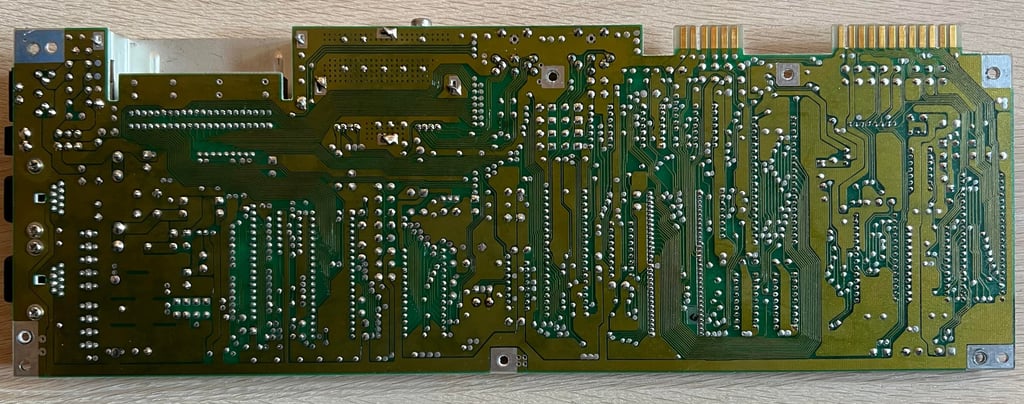
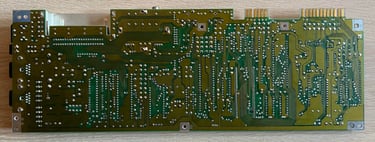
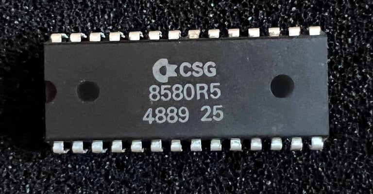
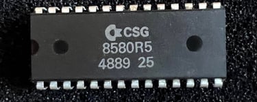
Below are pictures of the mainboard before repair. Note that the SID (MOS 8580) chip is removed. Since this chip is not required for the C64 to start I remove it to prevent it being damaged during repair. The 8580 is way more robust than the older MOS 6581 but I still think it is good practice to remove it before repair.

Visual inspection
There are no sign of corrosion or damage to the mainboard. In fact, it looks very good. None of the electrolytic capacitors seems to have leakage, and the fuse also looks to be intact. Below is a list of the main chips found on this mainboard (before repair).
My theory that this C64C was produced 2nd week of 1990 I think is strengthened by the fact that the chips on this board were produced around week 30 - 49 of 1989.
Checking the voltages
Before I start with any repair I measure the relevant voltages to make sure they are within acceptable range. A detailed description on how to measure these can be found here in my HOWTO article. Note that for the C64E PCB there are no +12 V and no 78xx voltage regulators so there are fewer measure points compared to the "longboard".
In the table below all voltages measured are listed. All voltages are ok and within acceptable range. This list will also be updated after refurbishment.
Fault finding
C64C produces only a black screen. But, it seems like it does produce a video signal - so hopes are that the VIC-II is ok. The "black screen" symptom is the most common fault on the Commodore 64. Nevertheless, the root cause of the black screen can be many so there is no immediate cause.
Since the MOS 8565 VIC-II, and its companion clock generator MOS 8701, are socketed it is easy to check these two since I have another working C64C with the same mainboard. It turns out that both these chips are working fine so the fault finding continues.
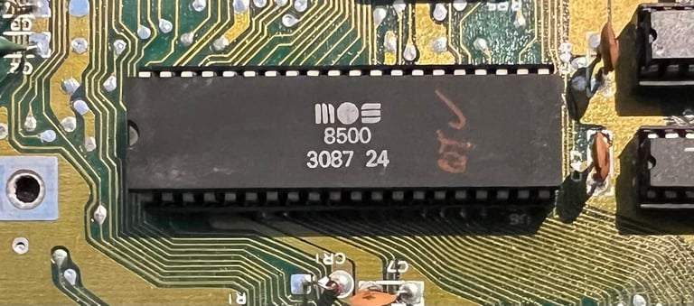
Next I touch all the chips while the C64C is powered on. After about five minutes I feel that the MOS 8500 CPU is getting hot. To be more precise; if I touch the center of the chip I feel that it is quite hot compared to the working C64C. Before starting investigating with the oscilloscope I choose to desolder and check the CPU.
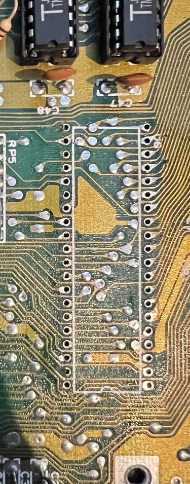
First I desolder and socket the CPU from the other C64C. This way I can check if the CPU is working or not. It turns out that to desolder chips on these board revisions is not trivial. But after some frustration I manage to desolder the CPU on both machines. The trick was to use both soldering iron and desoldering iron at the same time; the solder iron on the top of the PCB (close to the IC pins) and the desolder gun on the backside.
Below are pictures of the desoldered CPU from the mainboard. NOTE: I accidentally ripped a pad on the backside of the PCB (see blue square). But this pad was not connected to any trace (that is why these come off so easy). These things happens, but since the trace is only used on the front of the PCB no bodge wire is required.

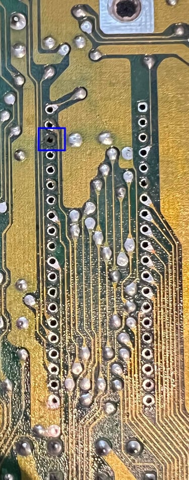
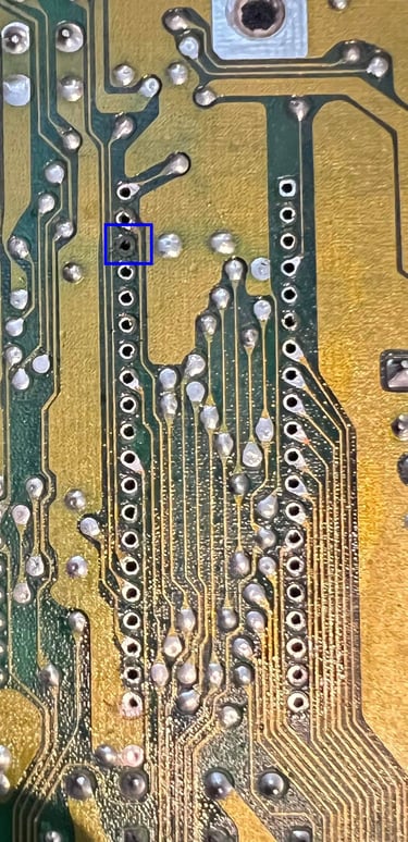
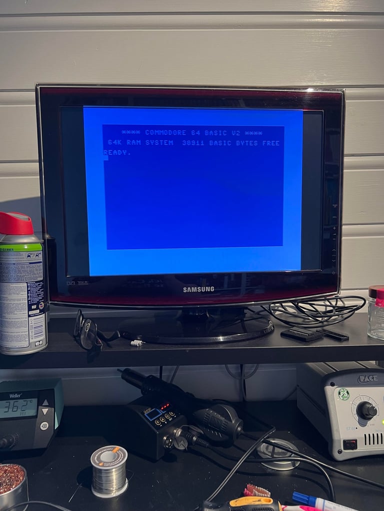
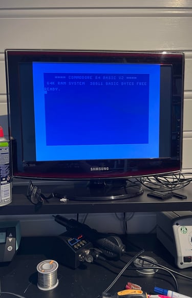
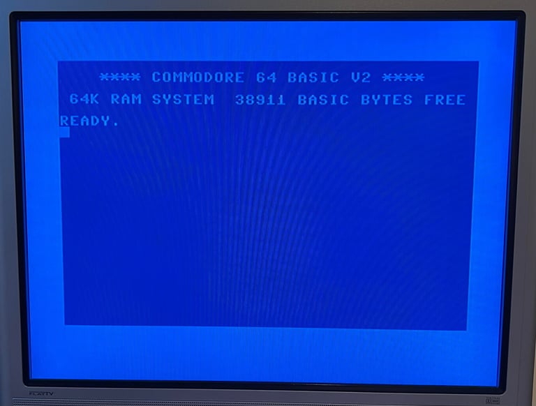
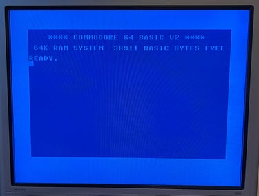
I solder in a new 40-pin socket and try the machine with a known working CPU. And the result is... BLUE SCREEN WITH 38911 BASIC BYTES FREE!
Replacing the CPU
When in need of Commodore 64 spare parts check with Retroleum.co.uk. A big thanks to Phil at Retroleum who provided me with super service - special delivery!
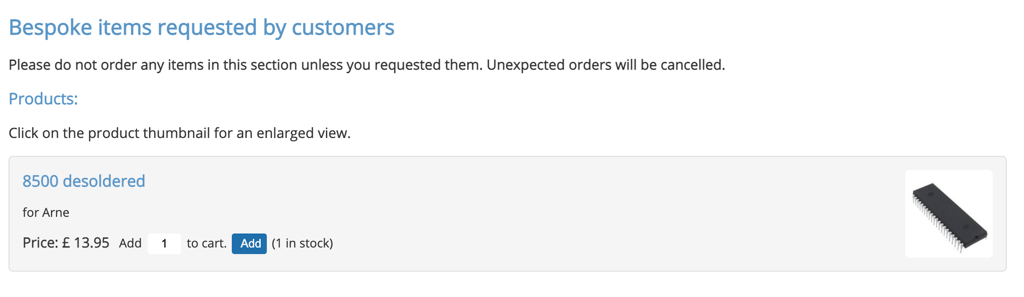

The new MOS 8500 CPU is from week 30 in the year 1987 and works (of course). In the pictures below are the new CPU and the mainboard after repair.

Testing
Testing is done through two main stages:
Testing the basic functionality and chips
Testing by using the machine playing demos, games etc. to verify correct operation
Basic functionality and chips
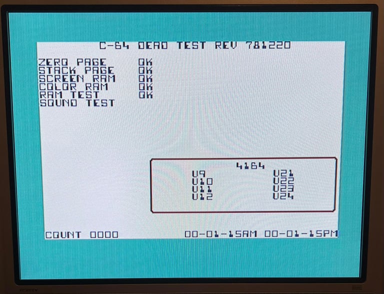
The first test is done by using the Dead Test Cartridge. This test will check the basic functionality of chips such as VIC-II, CPU, SID, CIA#1/2 and RAM (inc. COLOR). Nevertheless, it will not test everything that these chips can do. The dead test pass without any faults detected.

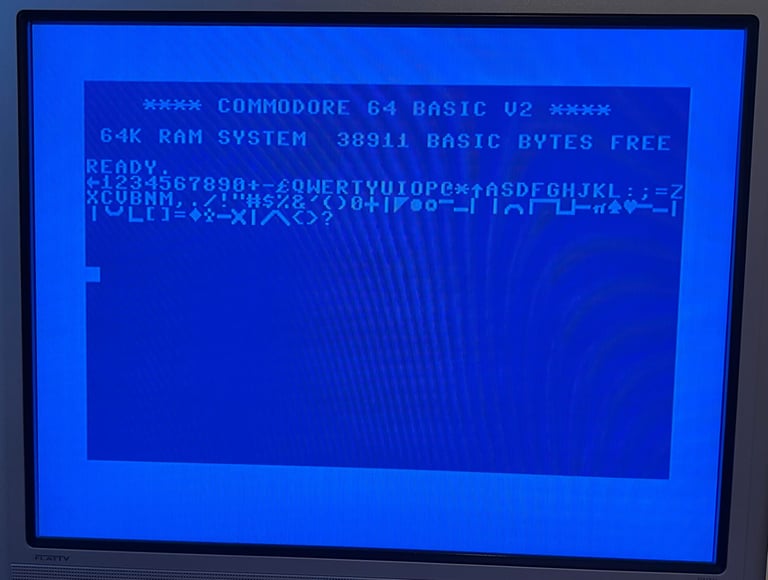
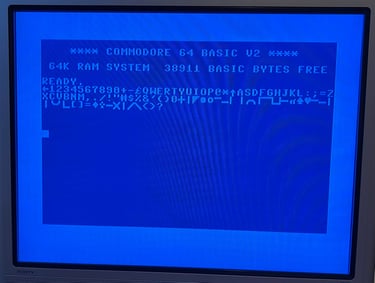
Next test it to check that normal startup screen is ok (with 38911 kB RAM Free and blinking cursor). Also, the keyboard is checked. All pass without faults.
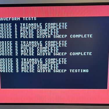
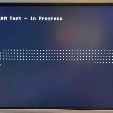
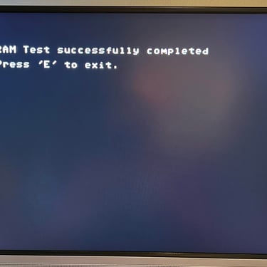
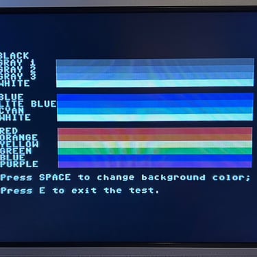
The basic functions of the VIC-II, SID and RAM is tested with 64 Doctor. Note that this is to be considered as basic functionality - more advanced (?) functionality such as sprite handling / collision detection / advanced audio will be tested later. But the basic tests pass without any detected faults (click to enlarge).
Extended testing
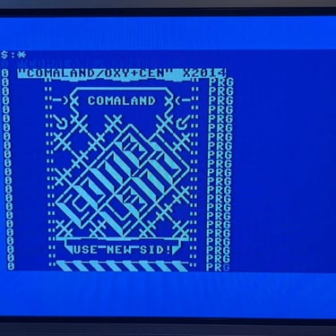
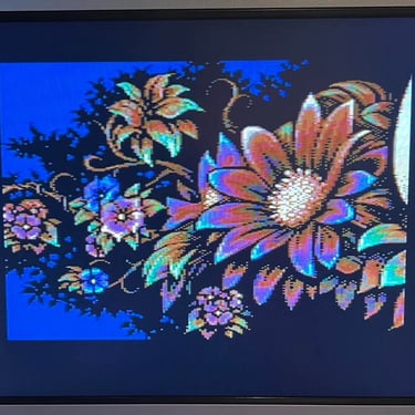
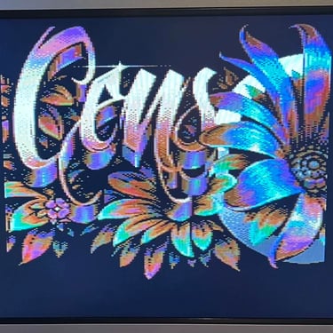
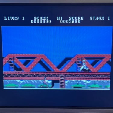
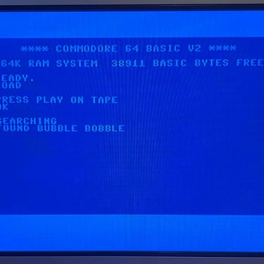
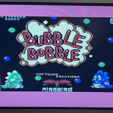
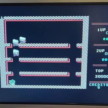
Knowing that the basic functionality of the machine works I continue the testing by using the Commodore 64 for normal operations; playing some games, watching demos, loading from datasette and floppy and using a cartridge. I can not find any issues with this machine. I also pay special attention to the video to make sure that there are no glitches in the graphics - I can´t see any abnormalities. Below is a gallery with pictures from the testing.