

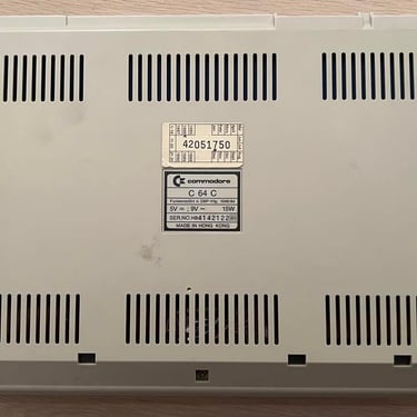
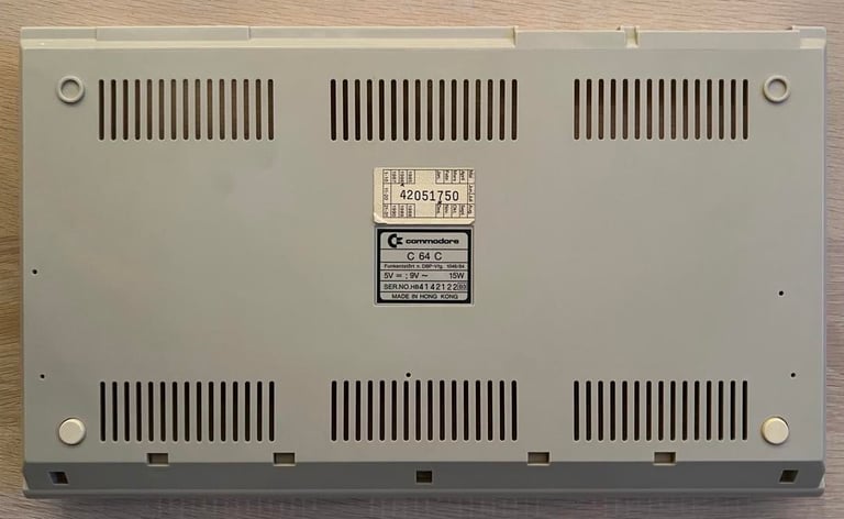
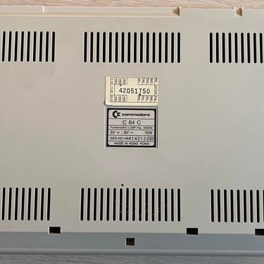
C64C
Ser. No. 4142122
Assy 250466
Refurbishment plan
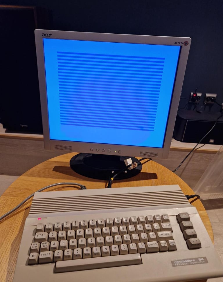
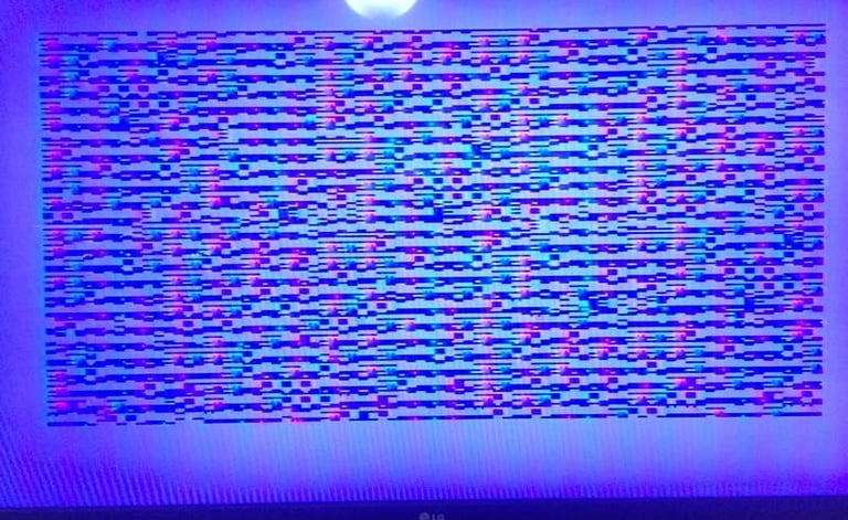
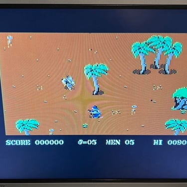
This C64C came to me as a request for refurbishment. There is a fault with this machine which means that it needs also some repair - a light blue border with alternating dark and light blue lines on the screen. See picture below (click to enlarge).
This C64C came to me as a request for refurbishment. There is a fault with this machine which means that it needs also some repair - a light blue border with alternating dark and light blue lines on the screen. See picture below (click to enlarge).
But in addition to the repair the plan is to do refurbish this machine by:
Clean and restore the keyboard
Clean and remove stains from the chassis
Refurbish main board (cleaning, checking, repairing, replacing capacitors and voltage regulators, adding heat sinks etc.)
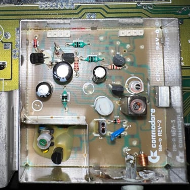
Recap RF-modulator
Verify operation by testing
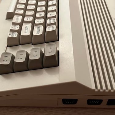
Also, I need to admit that this is my favorite version of the C64. The reason is that this version combines the best of two worlds:
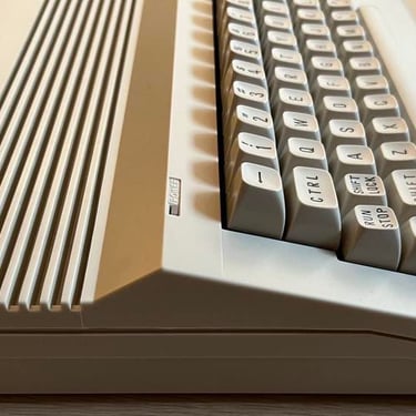
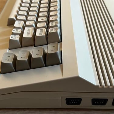
"New" chassis design and the "old" exclusive keys with symbols printed in front
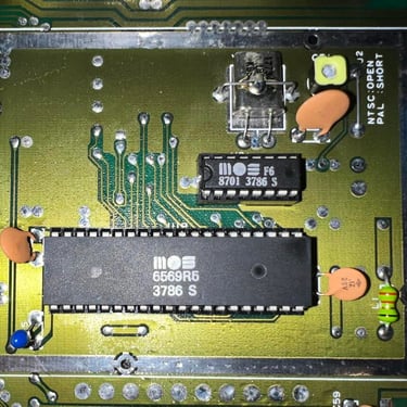
Inside it has the old longboard with the enhanced SID chip (MOS 6581R4AR) with ‘Advanced Resonance’ and the highly acclaimed MOS 6569R5 VIC-II chip
Here are some picture of the machine before the refurbishment starts:
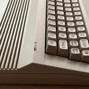
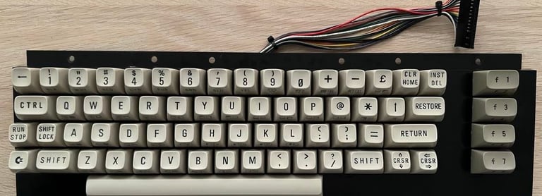
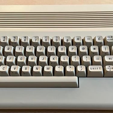
Keyboard
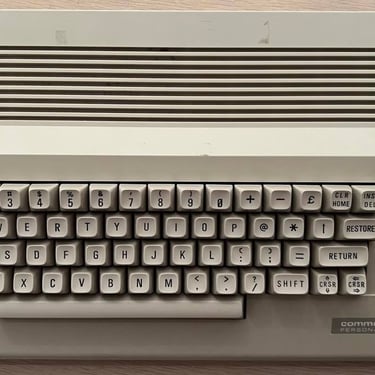
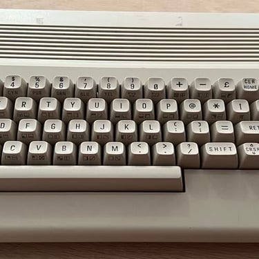
The keyboard looks very nice from the outside - nothing broken and no discoloring. There is quite some dust on the inside, but that is to be expected. Below is a picture of the keyboard where some of the keys are removed (with the keycap puller). Notice that the color of the keys are very nice - quite close to the original color I think.

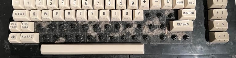
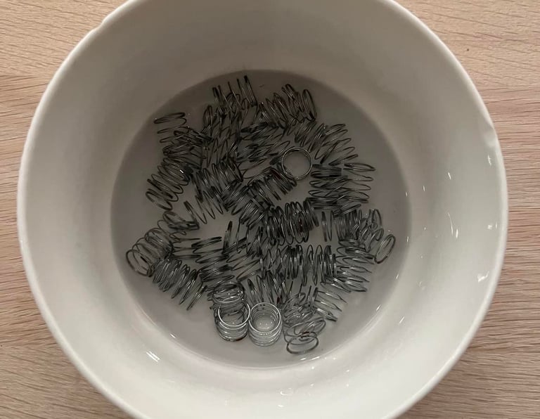
All keycaps are removed and the springs are put in a bowl of vinegar for 10 hours to remove rust. Note that the spring for the spacebar is different from the rest of the springs! So it´s smart to keep this in a separate plastic bag during refurbishment.
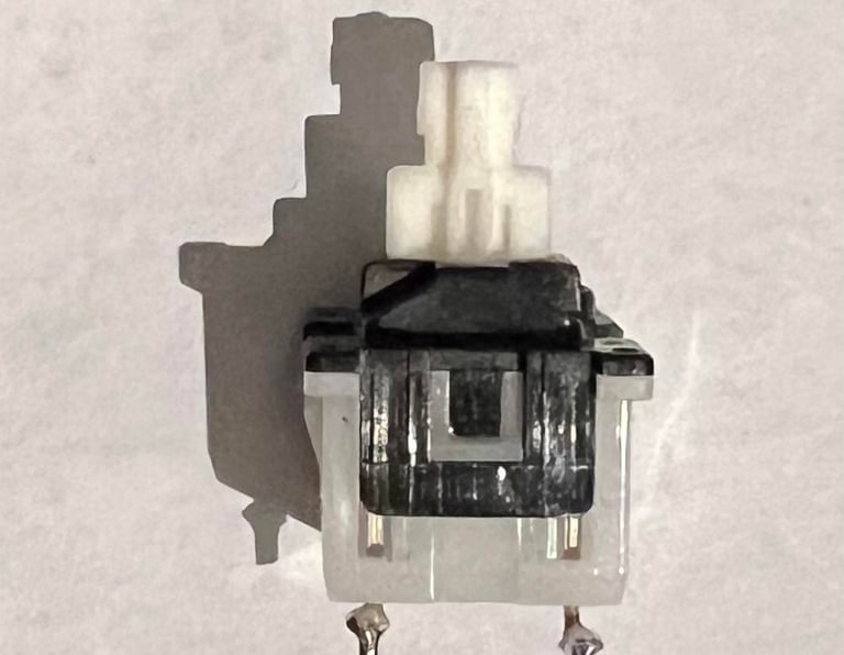
The Shift-Lock key have two small contacts which are soldered onto the keyboard PCB. These have to be desoldered before the key is removed. After these wires are desoldered you can push the key forward and it will "snap out" of the keyboard chassis. Below is a picture of the Shift-Lock key after some gentle cleaning.
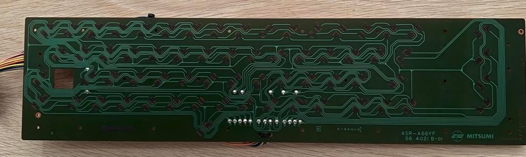
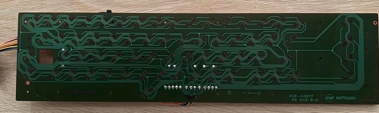
The PCB needs to be cleaned with isopropanol. To remove the PCB I need to unscrew about 2.5 billion small screws:-)! This is the usual PCB from Mitsumi - and as far as I can see there are no corrosion and/or damages to the PCB. The PCB is cleaned carefully with isopropanol to not damage the pads.
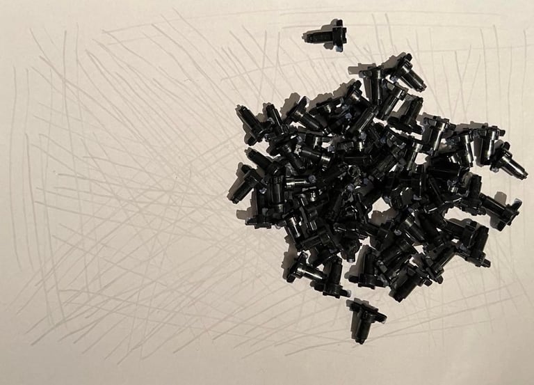
All plungers are removed from the plastic chassis and refurbished. The way I do this is by not using any cleaning liquid (isopropanol, water etc.) - but I only carefully drag each plunger over a clean paper. My experience on this method is that the keys then get "revived" and working! It´s quite normal that on old C64s that keys such as RETURN, SPACEBAR, NUMBERKEYS etc. stop working (or you need to push real hard). But with this method I normally get all keys working again.
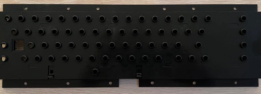
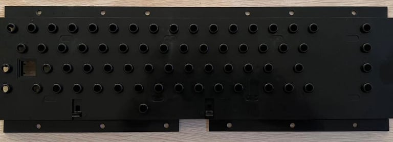
The plastic chassis holding all the plungers/keys are cleaned with mild soap water and luke warm water. See picture below (click to enlarge).
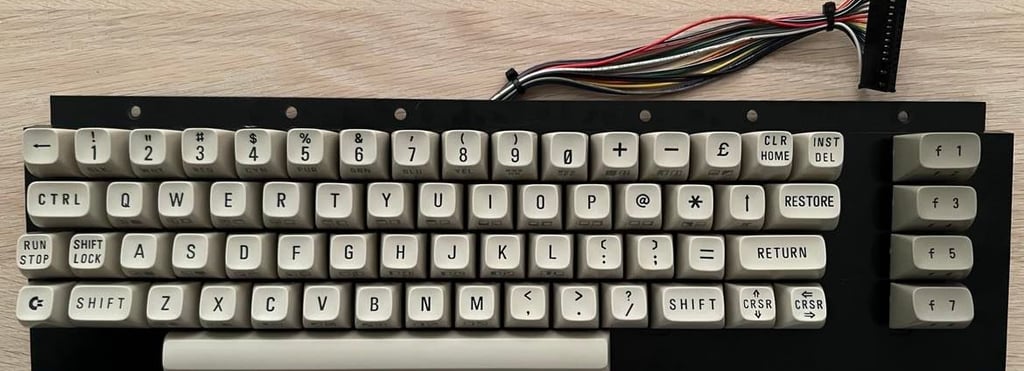
After all parts are cleaned, revived and dried the keyboard is assembled - and it turned out very well! Keyboard complete!
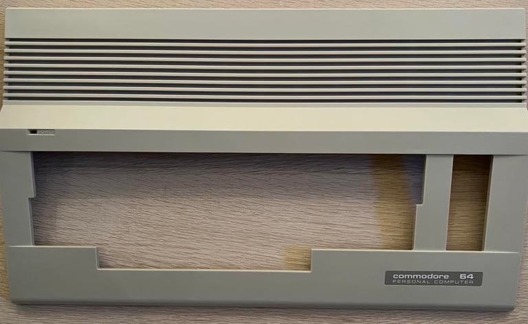
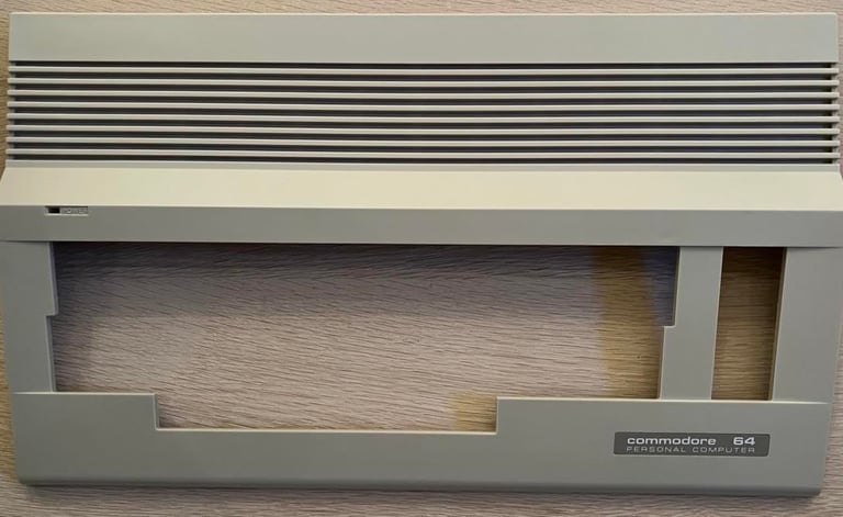
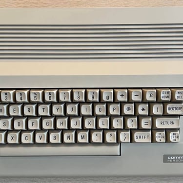
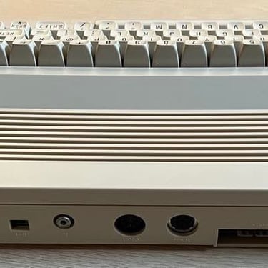
Chassis
The top- and bottom cover looks quite good. Only some stains and dirt - and no damages as far as I can see. Also, the discoloring is almost non-existing I think. This leaves me to the conclusion that it´s best to leave out the retrobrighting to reduce the risk of deteriorating the plastic.
Both top- and bottom cover is cleaned carefully with mild soap water, glass cleaning spray and some drops of isopropanol. See pictures below.

Main board
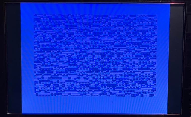
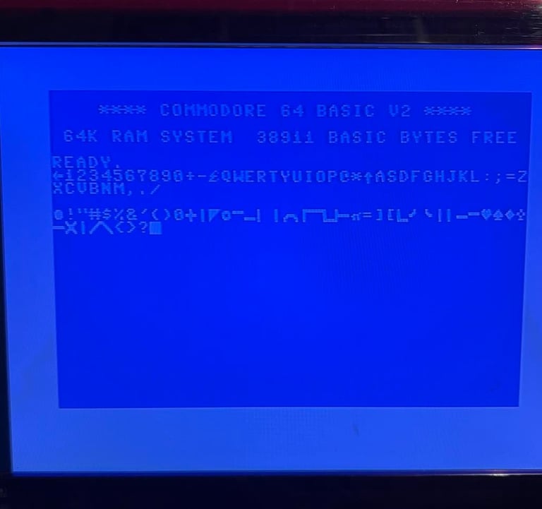
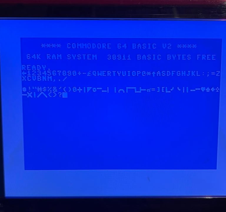
I know (?) that this main board is not working, but gives a blue screen as shown in the picture in the first presentation. Nevertheless, I test the board to see what happens. I also get a blue screen, but it´s somewhat different than the initial picture:
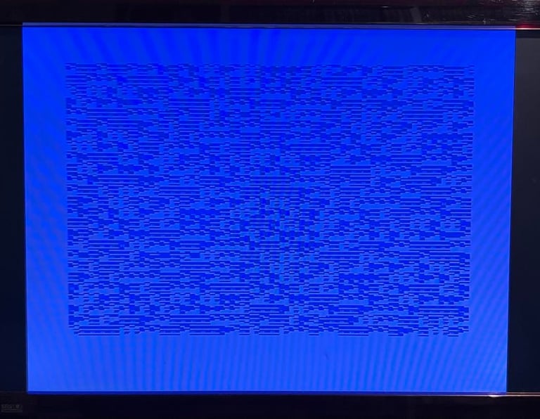
Even if it is somewhat different than the initial screen, I still think this is related to the same fault. Or there could be several faults. I first start with a visual inspection of the main board - and note that:
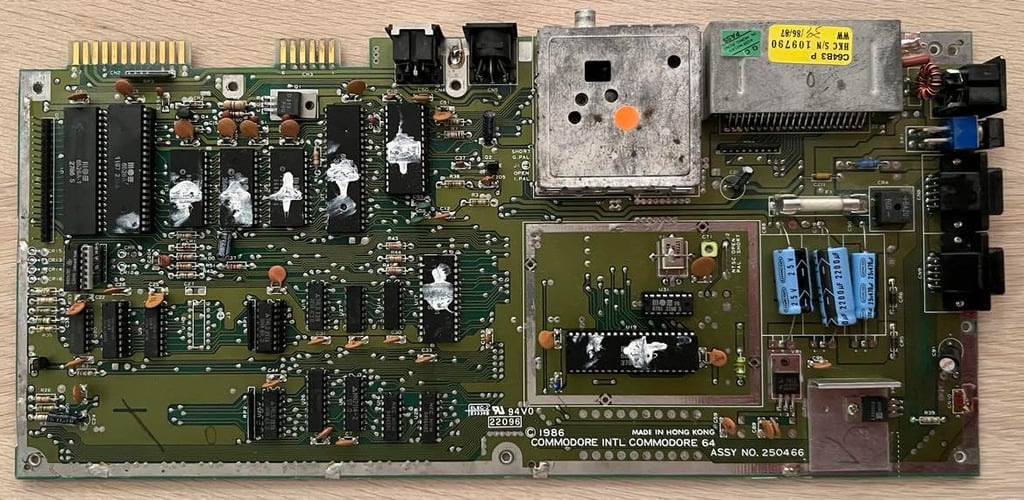
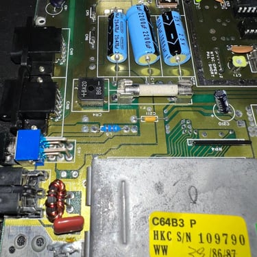
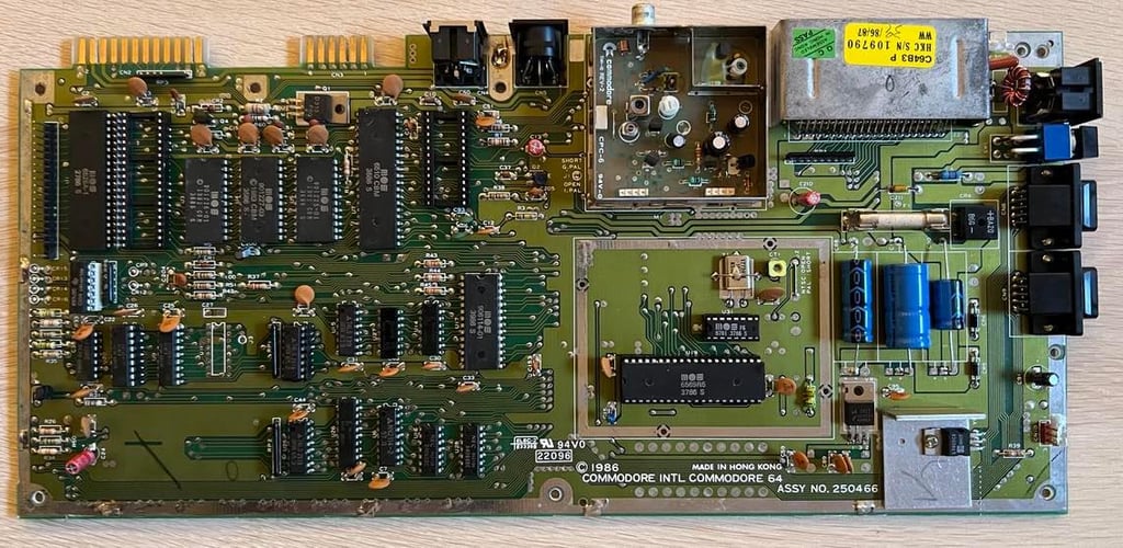
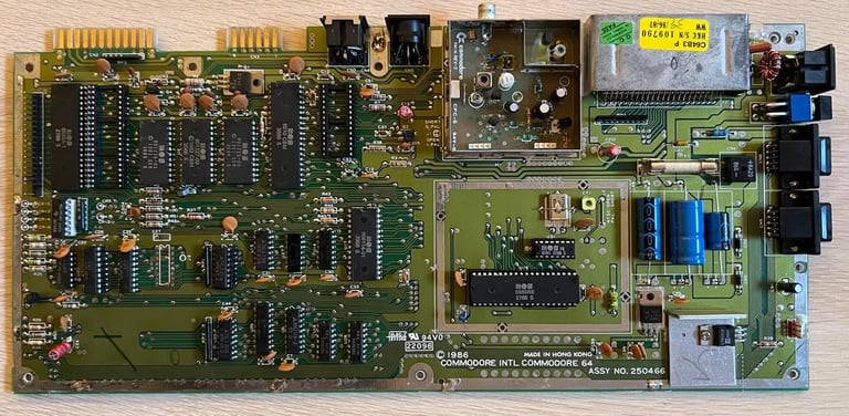
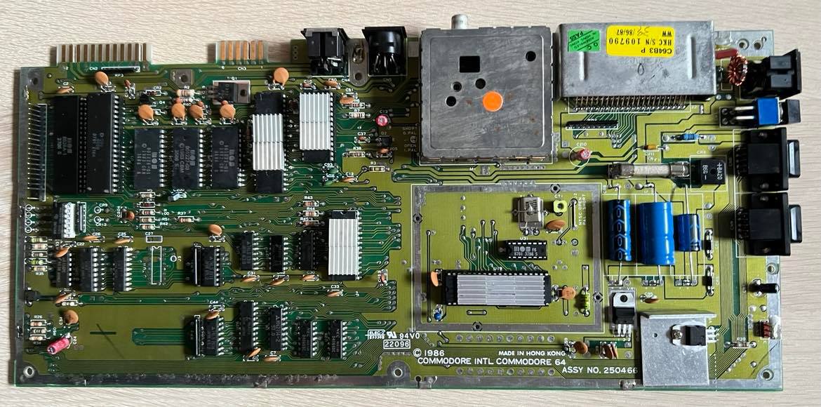
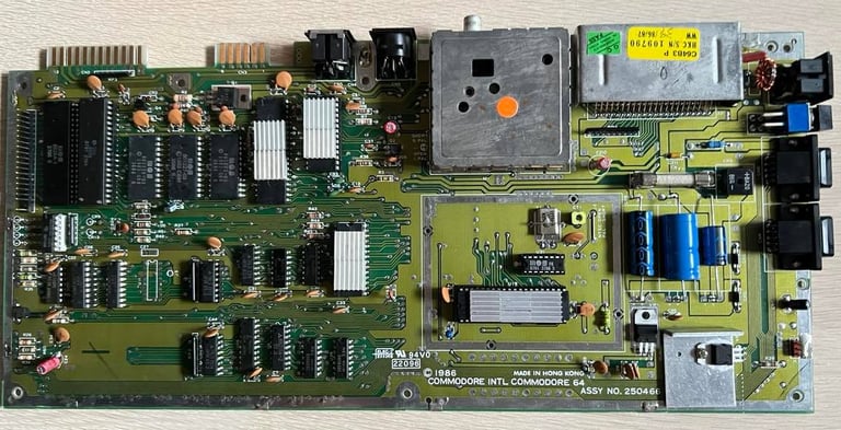
This is assy 250466 (YES! My favorite!)
It looks to be intact, but a bit dirty
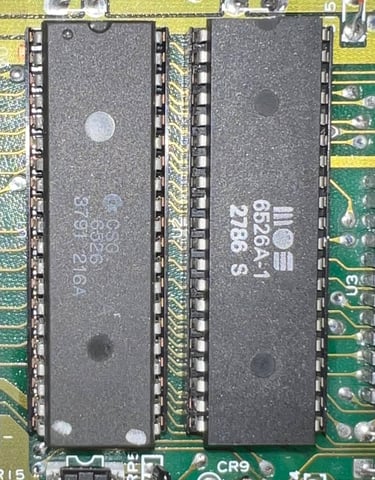
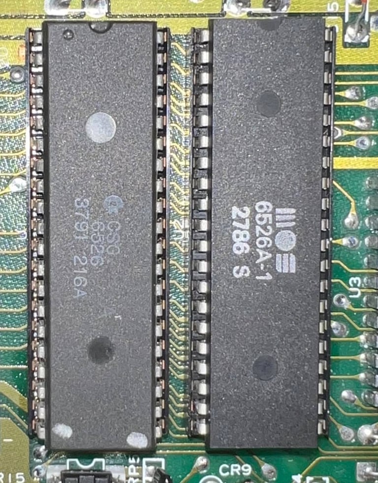
There is thermal paste on quite a few of the custom chips so it´s hard to read the date on the chips. But I see that CIA #1 is from week 27 in year 1986, and CIA #2 is from week 11 in year 1987.
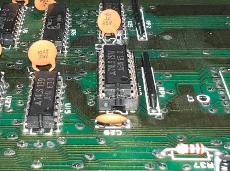
This board have been repaired previously; the CIA #2, 7406, 74LS257 and an OKI RAM chip
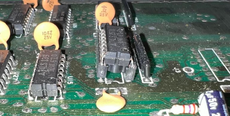
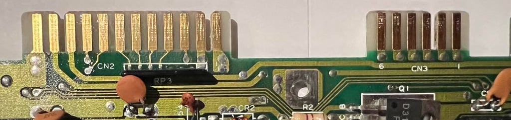
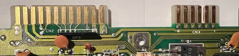
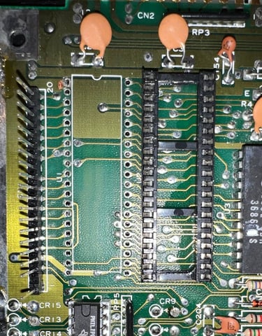
Below is a picture of the main board before cleaning and repairing commence.

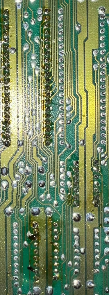
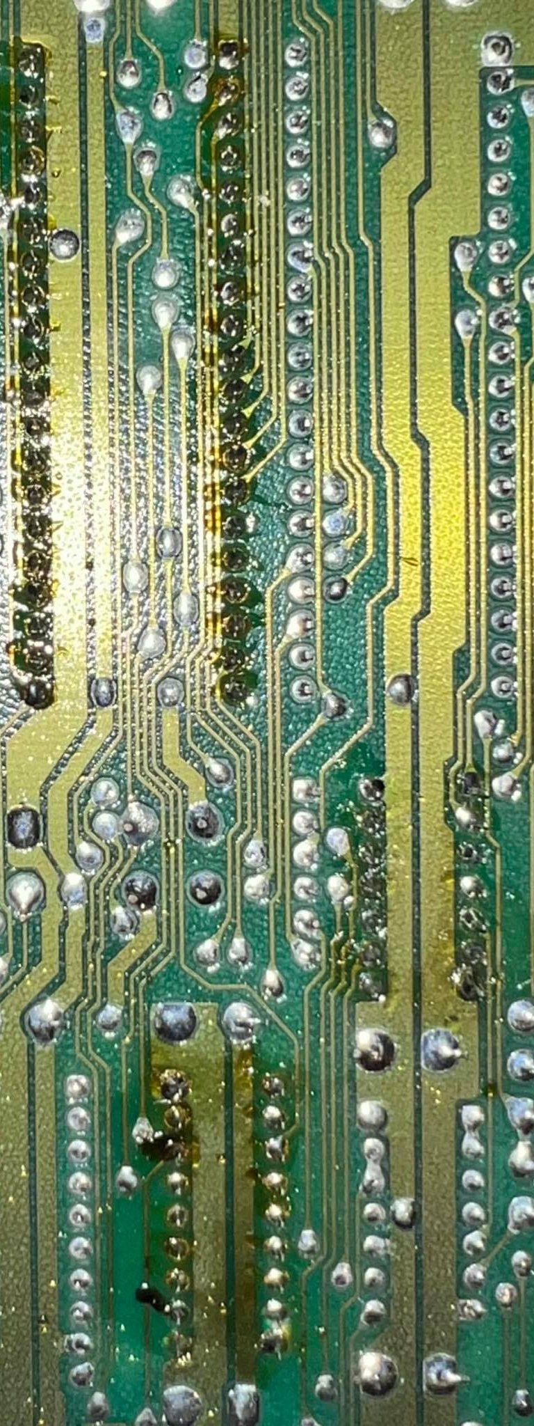
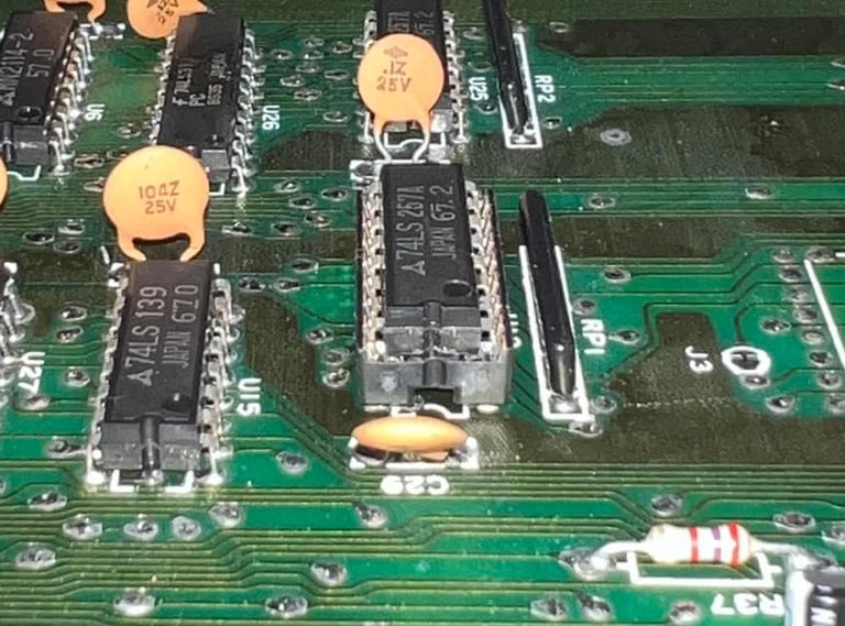
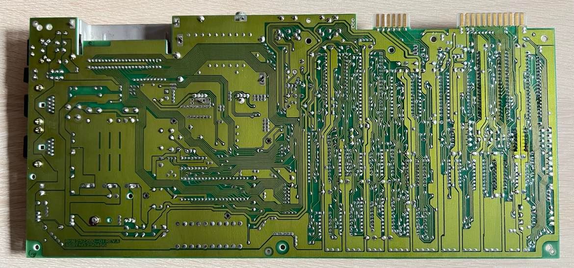
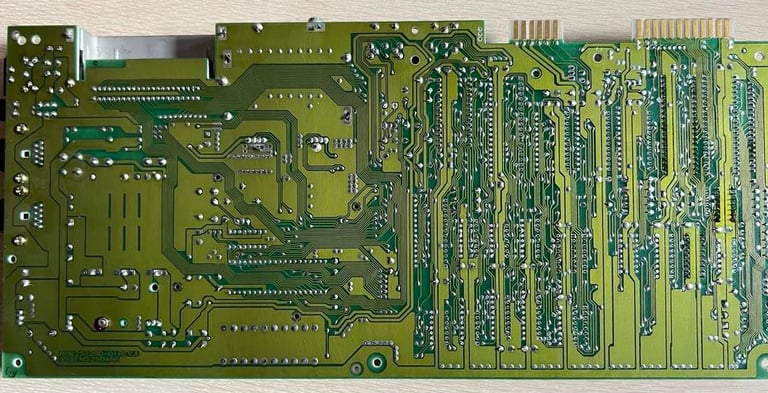
It´s quite easy to see which of the chips have been replaced by checking the back of the PCB. Here I see that old flux residue is present on the four chips mentioned before:
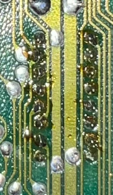
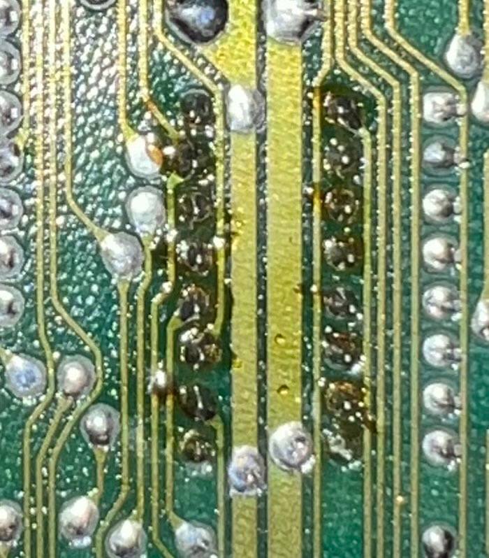
Another important thing with visual inspection is to look for potential faults. I find a suspect; the socket for the 74LS257 is not "flush" with the PCB. It´s a bit tilted when soldered in. See picture below (click to enlarge). Now, this does not mean that it´s a problem, but I will probably desolder this one and make it "flush" with the PCB to make sure that pin connectivity is optimal.

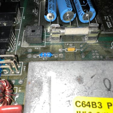
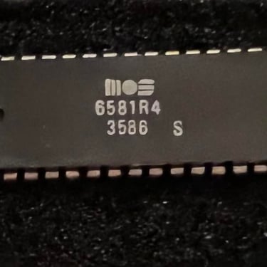
Before I start the fault finding I clean the PCB with some luke warm water and soap. But no worries, this will not damage the board and components in any way. What is important is that after this cleaning is that I use a lot of isopropanol to remove the water residue and to get all the water to vaporize. Also, as good practice before repairing is started is to remove the SID chip. This chip is not vital for the C64 to work - and since these are valuable is smart to remove them and replace them after repair. Now I see also that this is the incredible SID 6581 R4 version! In my opinion the VERY best SID chip! PS! It´s also smart to remove the fuse before cleaning! They can leak:-)!
It´s good practice to always start a repair with checking the voltages. I don´t expect there to be anything wrong with these on this C64, but let´s verify that they are within acceptable voltage levels. The custom MOS chips need a good and solid 5V (and sometimes 12V) to operate flawless. There are four voltages that I measure:
5 V DC from the PSU measured at the user port (See first picture)
9 V AC from the PSU measured at the user port (See first picture)
5 V DC (CAN) from the 7805 voltage regulator (See second picture)
12 V DC from the 7812 voltage regulator (See second picture)
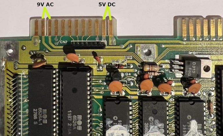
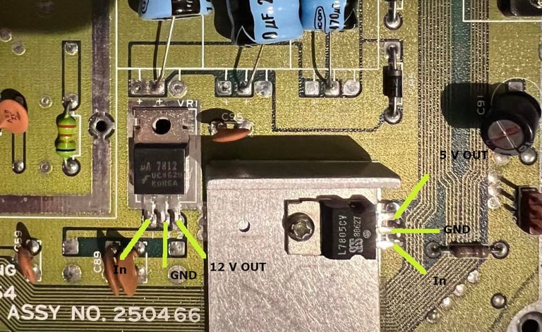
The 5 V from the PSU is used for most of the chips. The only exception is the VIC-II chip which have a separate 5 V from the 7805 regulator. Why? Well, I´m not really sure, but I can only guess that this is to prevent interference from the 5 V from the PSU which could cause disturbance in the videosignal. Also, the 5V from the 7805 regulator is often called "CAN". Can only guess here also, but that it´s referring to a "canned" area where the VIC-II is located (although the "tin can" is not present on this board). The 12 V from the 7812 regulator is used both for the SID and the VIC-II chip. The 9V AC on the user port is used with peripherals such as modems.
The measured voltages are as listed in the table below. Please note that this table will be updated after new electrolytic capacitors and voltage regulators are installed.
As far as I can see the outputs levels are good. I notice that the input voltage for the 7812 is almost 23 V. I have not seen this high voltage before I think - nevertheless I don´t think this is a problem since the output voltage is within range. Maybe this will change after recap and new capacitors?
The customer suspected the fault to be related to CIA #2 chip based on https://www.pictorial64.com/. And I agree. The picture below is taken from this pictorial guide - and yes (!) it looks quite the same? On the left you see the picture from the pictorial guide and to the right is the picture from this faulty C64.
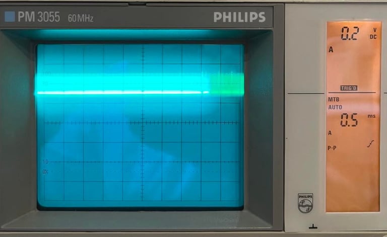
But before I start changing the CIA chips I use the oscilloscope to check the signals on the CIA #2 chip and compare this to the signal reference bank. I notice that some signals have an odd voltage level; not 0 V and not 5 V. And some signals seems quite ok. Below are two pictures - one from pin 2 which is obviously wrong and pin 19 which is ok (compared to my reference).
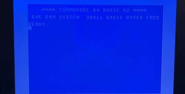
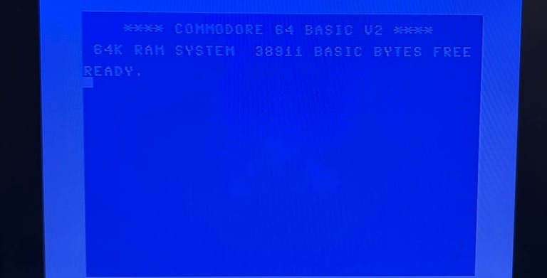
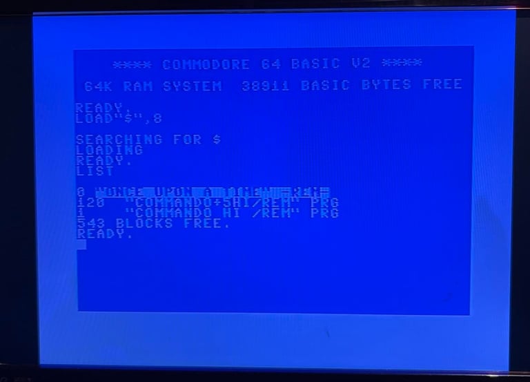
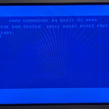
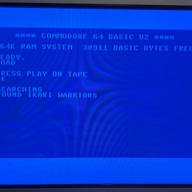
This is to me a clear indication (odd voltage levels) that something is wrong. It can be the CIA #2 or it can also be something connected to CIA #2. Since the CIA#2 is socketed it´s easy to check with a know good MOS 6526 chip. And... lo and behold! It works! The well known blue screen BASIC screen with 38911 Basic Bytes Free is back! So a new MOS 6526 CIA chip is ordered from https://www.retroleum.co.uk/.
After the cleaning the PCB looks way better - and I now can verify that this main board do have the acclaimed VIC-II 6569R5. That´s really nice! Now, we have made sure that this board have both the "right" SID and VIC-II chip! Phew! Below are some pictures after the cleaning and the VIC-II.
Next step is to replace all the electrolytic capacitors. It´s not crucial to replace these, but good practice. These capacitors tend to dry up due to old age and when capacitors have the "wrong" value you can experience weird behavior from the C64. I use quality capacitors from Kemet, Wurth Electronics and Panasonic/Vishay. This main board have the following electrolytic capacitors:
2200 uF [16 V]
1000 uF [25 V]
470 uF [25 V]
100 uF [16 V]
22 uF [25 V]
2 x 10 uF [25 V]
2.2 uF [50 V]
Below is a picture of the main board with the new electrolytic capacitors installed.
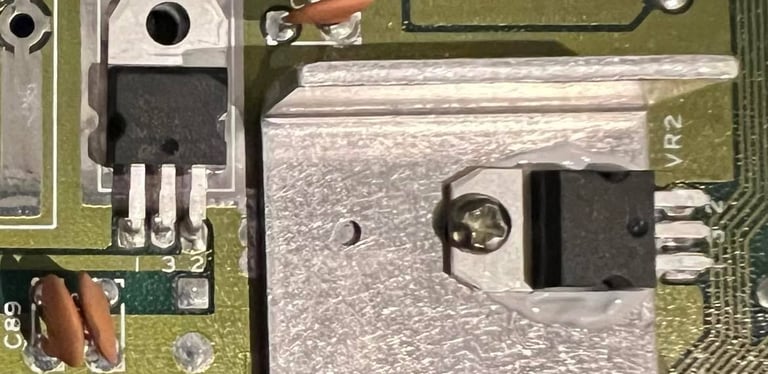
The two on-board voltage regulators, 7805 and 7812, are replaced. These are old and it´s good practice to replace these since the MOS custom chips are so sensitive to high voltages. Note that the 7805 (5 V) regulator is mounted on a heat sink with some termal paste, and the 7812 (12 V) is not. This is the way these were mounted at fabrication. Below is a picture of the new voltage regulators installed.

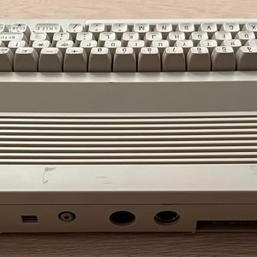
Before I start working on the RF-modulator I clean the datasette- and user port. It´s not uncommon that e.g. reading from tapes fail due to bad connectivity on the datasette port. The way these two ports are cleaned is with a rubber eraser and isopropanol on a q-tip. Picture below show the cleaned ports.
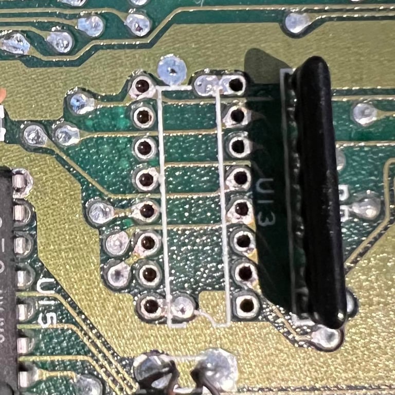
As previously mentioned the 74LS257 (U13) was poorly socketed. It´s wise to have the sockets "flush" with the PCB to make sure all contacts (both between the chip and socket - and between socket and PCB) have good connectivity. Therefore I desolder the old socket and replace it with a new one. No traces or pads were liftet/damaged, and I can´t see any damage done when the previous socket was installed.
RF modulator
There are some electrolytic capacitors in the RF-modulator which I want to replace. The hard thing with this operation is that great care must be taken to remove the RF-modulator. If you rush this job, you are likely to damage either the main board pads or the pads inside the RF-modulator.
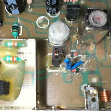
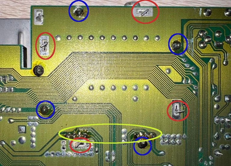
This is how I remove the RF-modulator:
Align the four pins to be parallell with the hole (red colored circle)
Desolder the four pins. I use both the solder iron and the desoldering gun to do this since the pins are so large (blue colored circle)
Desolder the eight pins that connect the RF-modulator to the main board PCB (yellow colored)
While using the hot air gun around all the pins I carefully pry a small flat screw driver in between the RF-modulator and the main board. After a while the RF-modulator come loose.
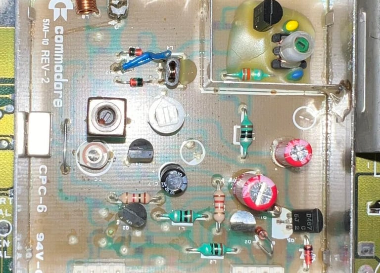
Unfortunately, I forgot to take a picture of the RF-modulator removed. But no traces were lifted. In the RF-modulator the following electrolytic capacitors (I use only quality brands) are replaced:
100 uF [10 V]
330 uF [10 V]
10 uF [16 V, but replaced with 25 V]
See picture below for the RF-modulator with the new capacitors installed.
Now that all the electrolytic capacitors are replaced with new one (both on the main board and in the RF-modulator) I update the voltage level table in the "main board" chapter above.
Heat sinks
With a new 6526 CIA chip (from week 37 in 1991) the C64C is now repaired and soon ready for final testing. But before I reassemble everything I add heat sinks to the VIC-II, PLA, SID and CPU chip. It may be that this is not strictly required, but I do believe that by adding these heat sinks that it will increase the probability of longer lives of these chips.
Below are pictures of the completely refurbished main board with all the chips and the heat sinks in place.
Testing
It´s time for testing! Does the C64 work? During refurbishing the machine looks ok, but I haven´t tested it completely yet. I split the testing in two parts:
#1: Testing the main chips such as PLA, CPU, VIC, RAM and CIA with the Dead Test Cartridge. Also testing the keyboard.
#2: Thorough with the use of Ultimate II+ cartridge to emulate datasette playback and floppy access to test with demos and games to make sure it works ok
Test run #1
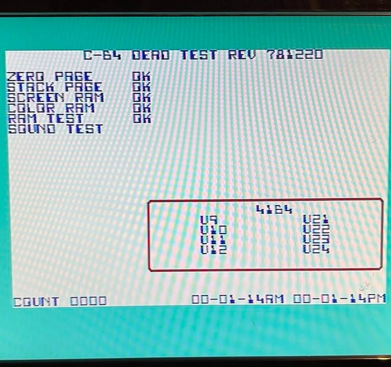
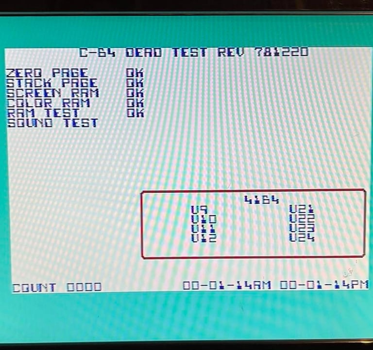
The dead test cartridge show "OK" on all major chips
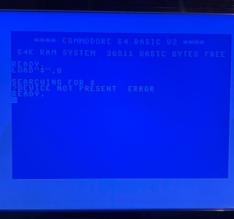
Test run #2
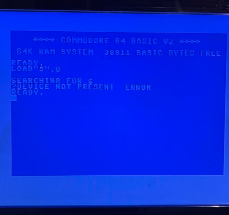
I quite immediate identify a problem - I get an error message "?DEVICE NOT PRESENT ERROR". Oh no... This means that there is something wrong still with the machine. Also, this is why it´s important to test thoroughly to make sure everything works! Back to the repair bench! See picture below for error message.
Keyboard working ok
Fault finding and repair
The testing revealed that there is something wrong with disk access. The CIA #2 chip is connected to the serial port of the C64. This chip is the one we´ve replaced earlier, but I try with another one to see if that fixes it. But the result is negative - still the same.
Next, I resolder all the contacts on the CIA#2 socket and spray with contact cleaner. I do this to see if there is a bad connection somewhere. But, no, same result.
I choose to desolder and socket the CIA#1 chip also. This chip is not directly involved in the serial port communication, but I think it´s ok to try anyway. And nice to have this in a socket also. The desoldering process works fine - no traces or pads lifted. It´s always a bit tricky to remove these 40-pin large chips but I use a combination of desoldering gun and hot air. See pictures below; no traces or pads lifted and both CIA socketed.

But... no... even with two known working 6526 CIA chips installed I get "?DEVICE NOT PRESENT ERROR".
In the quest for finding this fault I check the C64 Service Manual (source: https://support.retrorewind.ca/_media/commodore/c64/c64c_service_manual.pdf). And in this manual I find the schematics on how the serial port is connected to the CIA#2 chip.
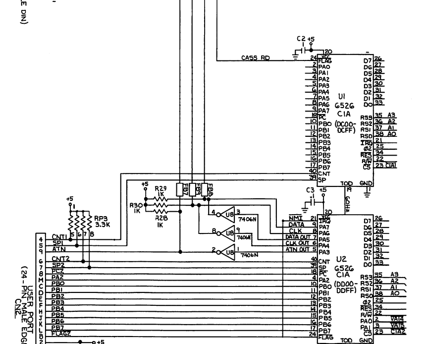
From this manual is says:
"U2 is a Complex Interface Adapter (CIA). Parallel port signals PA3-PA7 control the serial bus interface. PA3 is the Attention (ATN) output. This signal is inverted by U8 before being transmitted to a device on the bus. PA4 is the Clock output. Data transmitted from the C64 to a device on the bus is synchronized by this clock signal. U8 inverts the output PA4. PA5 is the data output. U8 inverts this output also. Data transmitted from a device on the bus to the C64 is synchronized by a clock generated by the transmitting device. The Clock signal is input on PA6. Data transmitted from a device on the bus to the C64 is input on PA7. When a device on the bus wants to communicate with the C64, SRQ IN goes "low" indicating service is requested. "
The plan is to investigate:
Connectivity between the lines from the serial input to the CIA#1, CIA#2 and U8
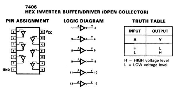
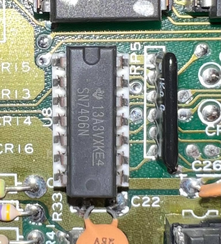
Check signals on U8. This is a 7406 Hex Inverter. Possibly also replace this.
Starting by checking connectivity. See table below.

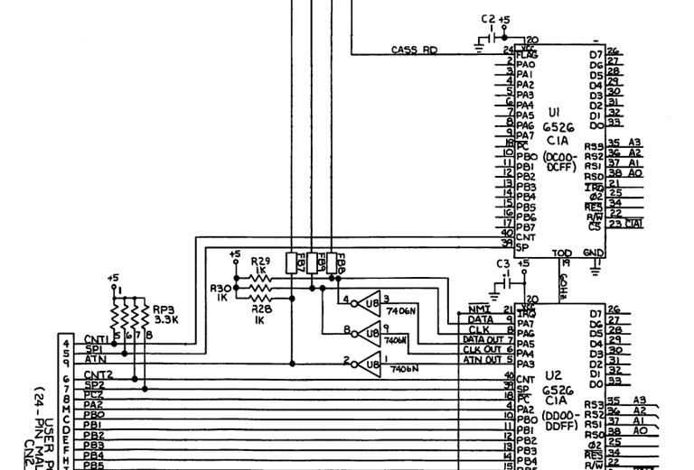
After first thinking that several connections are faulty I realize that the pin used in U8 (7406) is different for this assy 250466 mainboard than the figure above describes. The correct pin configuration is in schematics number 252278 in the service manual. It is these that are used in the table below - which shows that all connections are ok. Just for reference: there is also a signal on Serial input 6 which goes to transistor (collector input) Q3. This is not in the table but it is also verified ok.
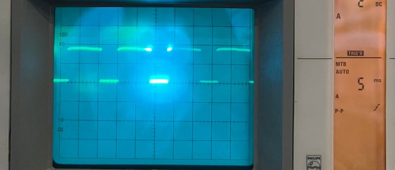
Next step is to check the signals on the U8 7406 chip which is in between the CIA#2 and Serial bus. This is a hex inverter described in the figure below.
All pins looks fine. That means that if an input is "low" then the output is "high". On pin 3 and 4 there are signals which also looks ok as far as I can see. Input amplitude is between 0-4 V and output is between 0-5 V. See pictures below.
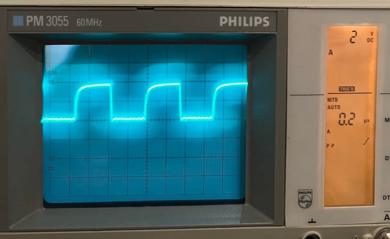
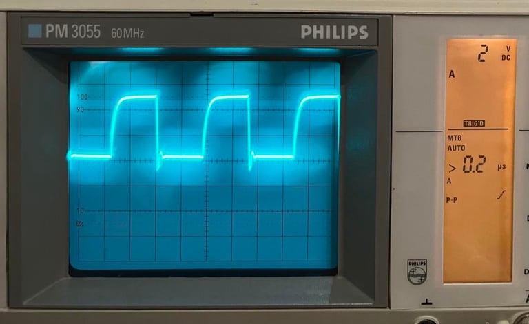
Even if the signals looks ok as far as I can see I try with a new known working 7406 just to rule out that this is the culprit. But... LO AND BEHOLD! It works! Why?! Oh my.... I really don´t get this! But it works! Perhaps the old 7406 was marginal?!
So this little glue logic saved the day...
Testing - Continued
After doing the final (hopefully) repair it´s time to continue testing. First I test the SID, VIC-II and RAM in some more detail with the 64 Doctor software. And these tests pass without any errors.
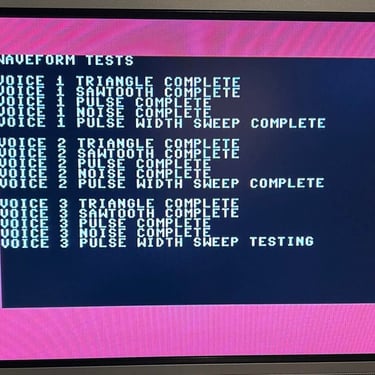
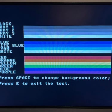
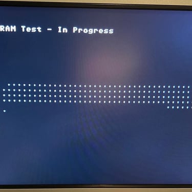
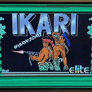
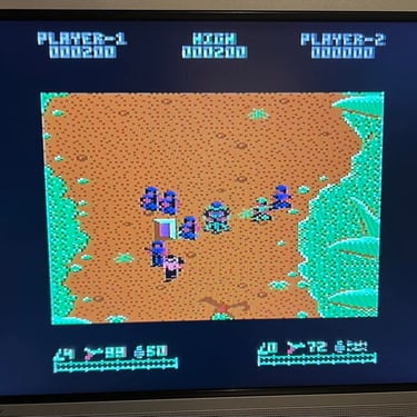
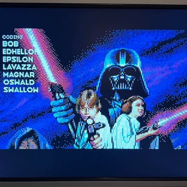
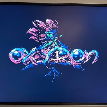
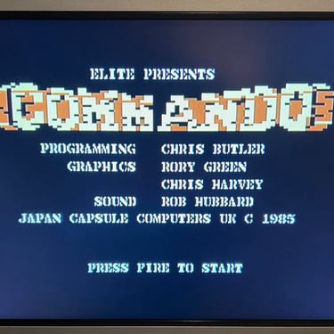
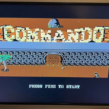
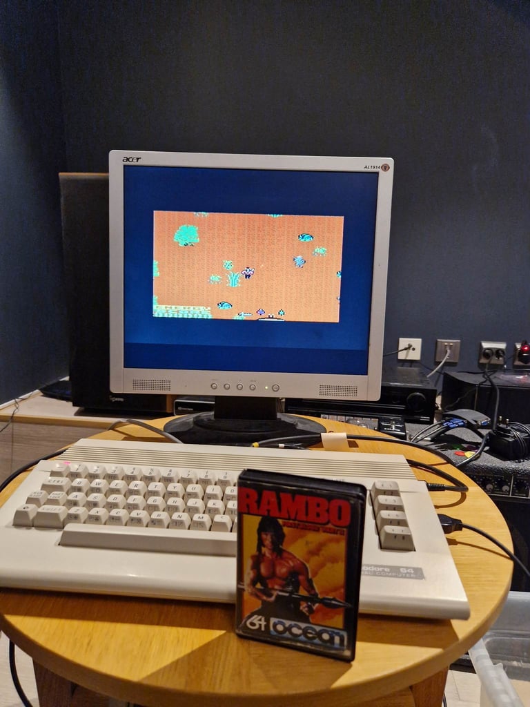
I use the UltimateII+ cartridge to test datasette playback and disk drive access while playing some games and watching demos. And all of these works fine as far as I can see. No problem here! My conclusion is that this C64C is now working as it should. Below are some screenshots from the testing.
Final result
"A picture worth a thousand words"
Below is a collection of the final result from the refurbishment of this C64C. Hope you like it! Click to enlarge!
"Are you keeping up with the Commodore? 'Cause the Commodore is keepin up with you!"
Below is a picture of the Commodore 64C back home at the customer!