

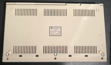
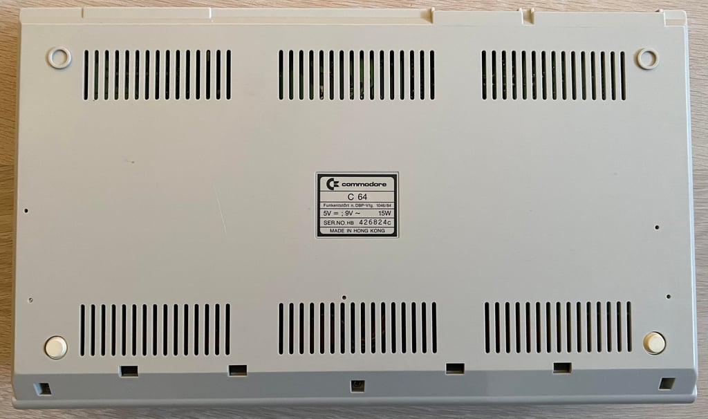
C64C [PAL]
Ser. No. 426824
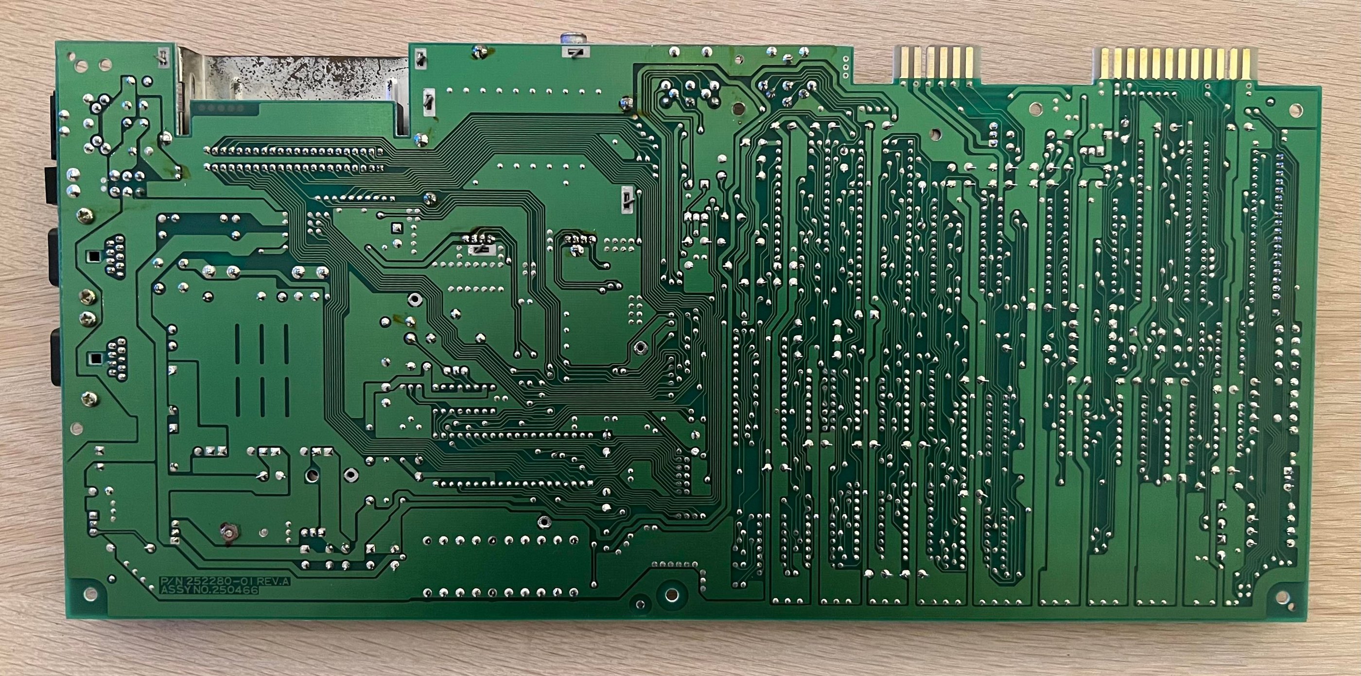
Assy 250466
P/N 252280-01 (REV A)
Starting point
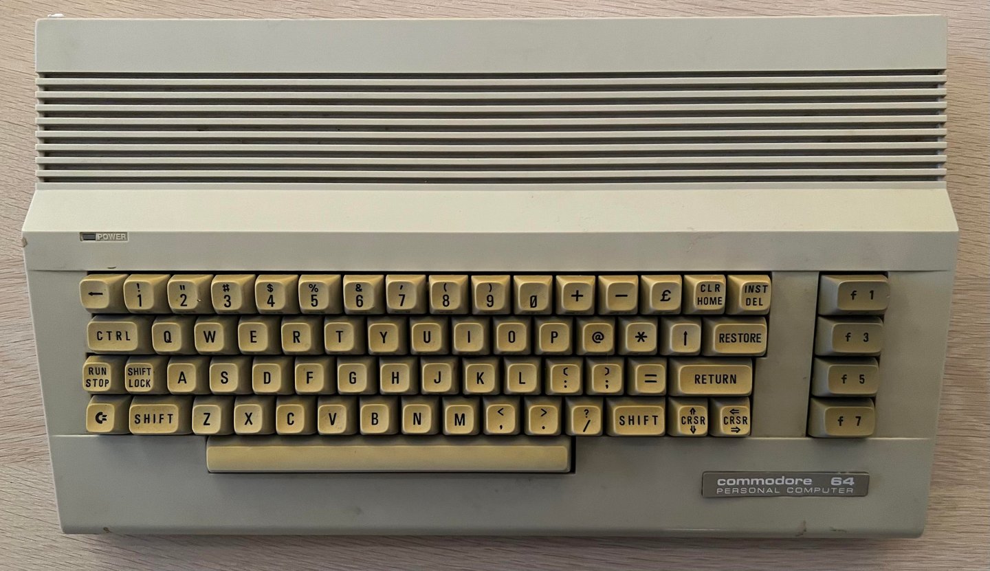
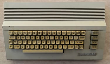
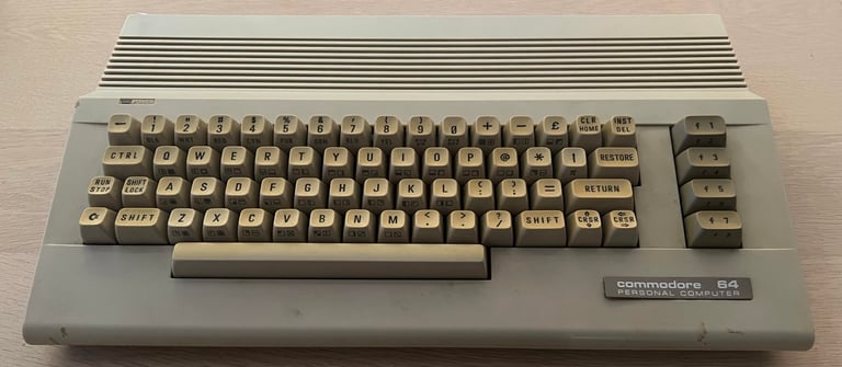
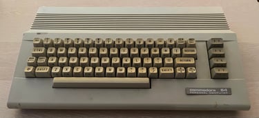
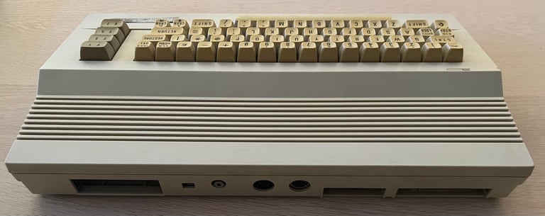
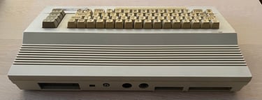
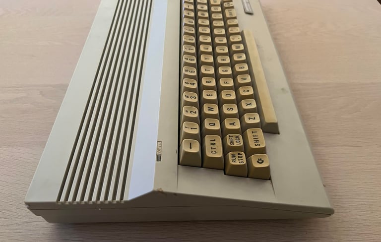
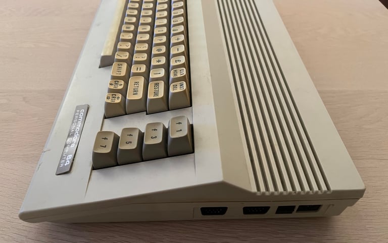
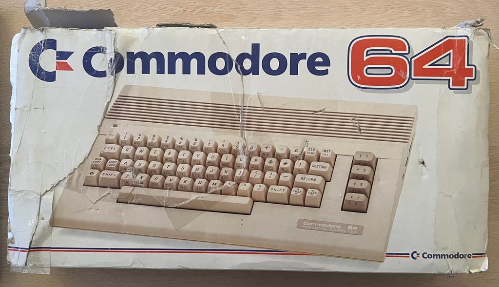
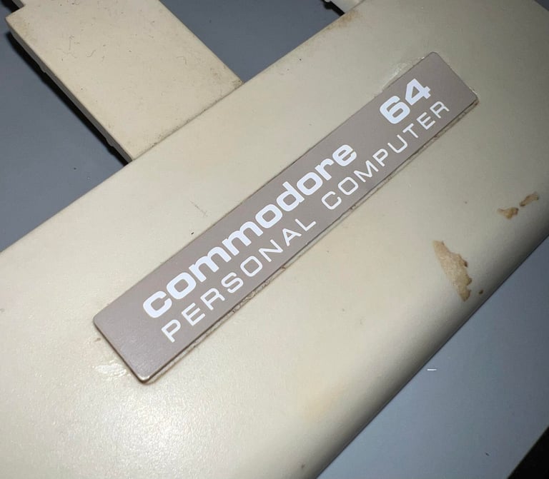
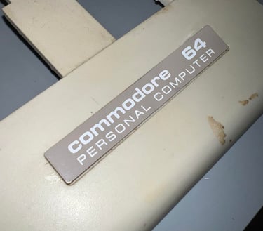
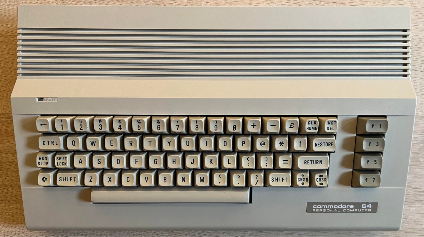
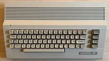
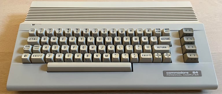
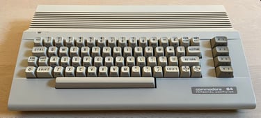
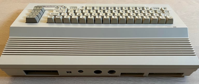
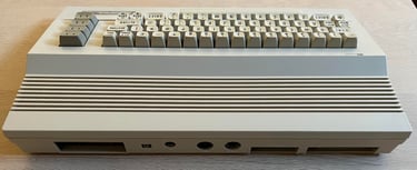
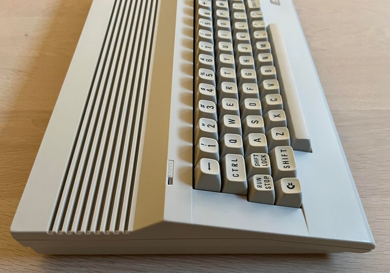
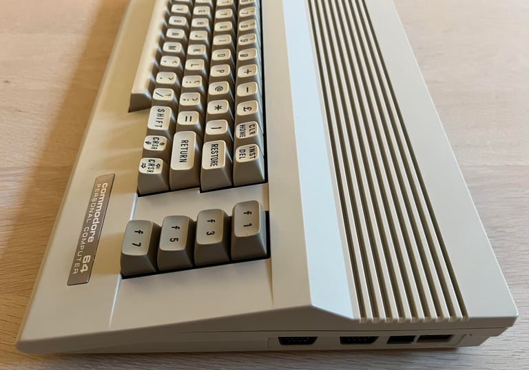
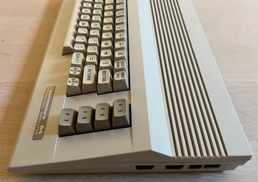
What´s my favorite colour? YELLOW! This Commodore 64C looks to be in quite ok condition in general, but holy moly it is yellow. The keycaps are particularly yellowed. There is a lot of dirt and grease on the cover and in between the keys. The "Commodore 64" metal badge is severely bent and bulged - I assume a previous owner has tried to removed this with brute force... I have no idea if this machine works or not before refurbish.
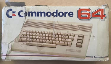
A very damaged cardboard box follow the machine.
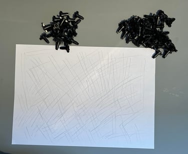
Below are some pictures before the refurbishment.


Refurbishment plan
The refurbishment plan for this C64C (order can vary and some of the tasks will be done in parallell):
- Clean and remove stains from the chassis
- Clean and restore the keyboard
- Refurbish main board (cleaning, checking, repairing, replacing capacitors etc.)
- Replace the RF-modulator with C64 Longboard RF replacement V2
- Verify operation by testing
The plan can be updated during the refurbishment process. Sometimes I discover areas that needs special attention.
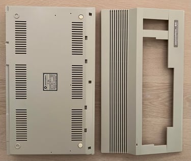
Opens it up...
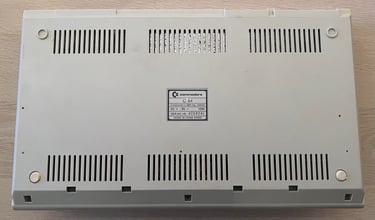
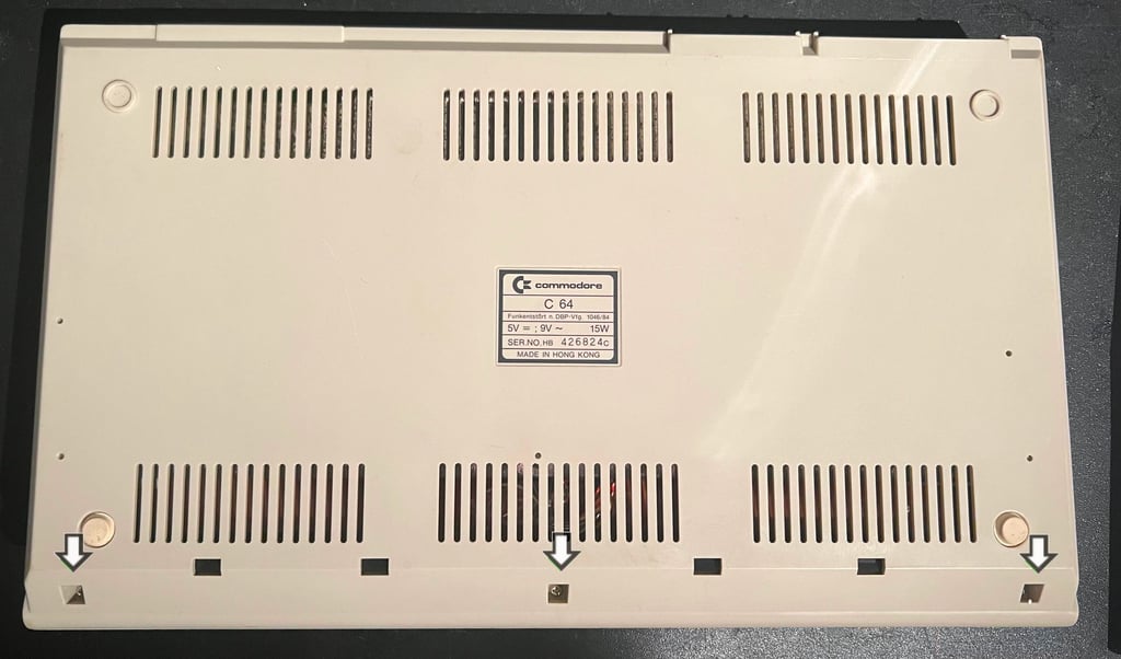
The C64C consists of a top- and bottom cover helt together with rear clips and three screws at the bottom. To open the C64C the screws at the bottom cover are removed first.
The front cover and keyboard is tilted about 30 degrees and then wiggled off the rear clips before lifting it to 90 degrees angle. As can be seen from the picture below the inside appears intact, but full of dust and dirt.
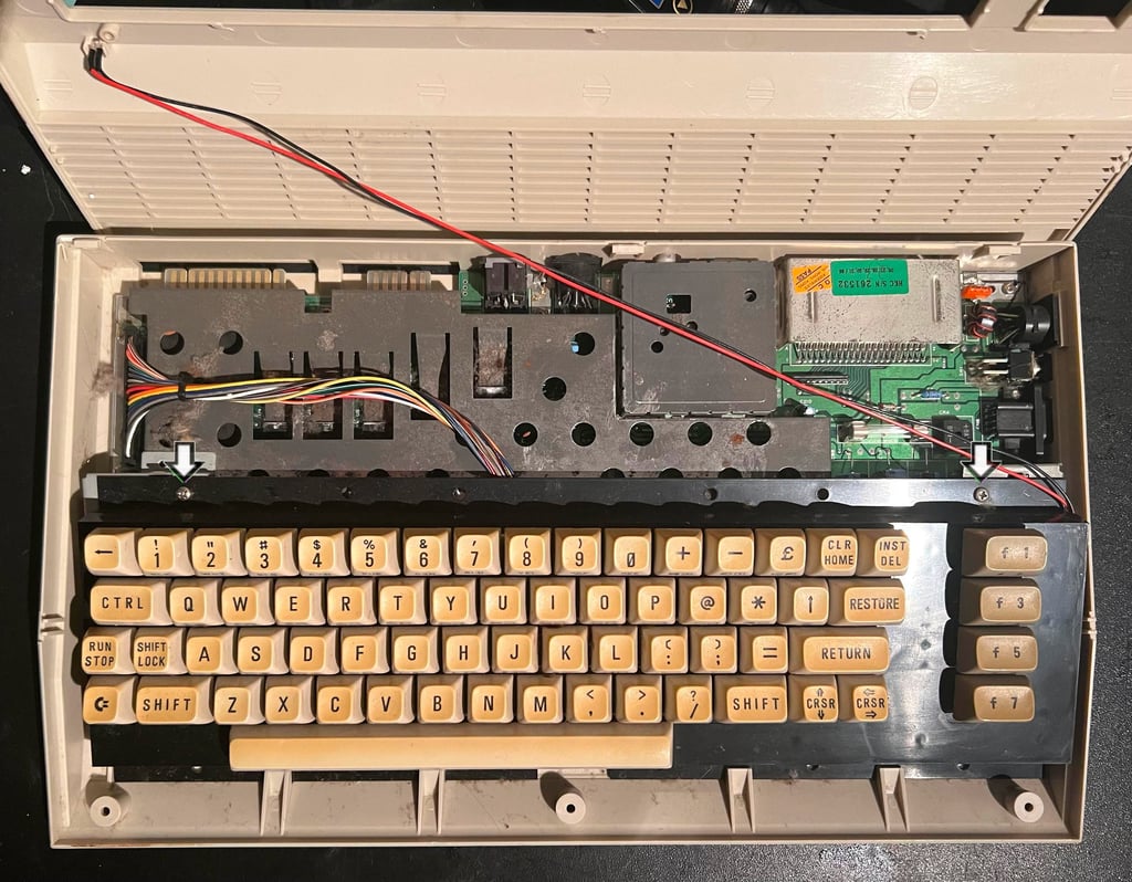

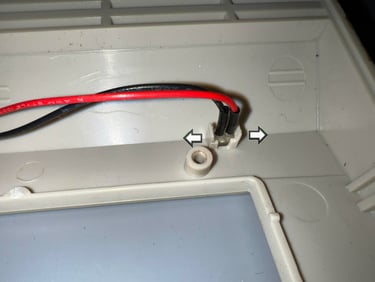
To lift the keyboard away the two machine screws are removed (see two arrows above). Both the keyboard- and LED connector are disconnected.
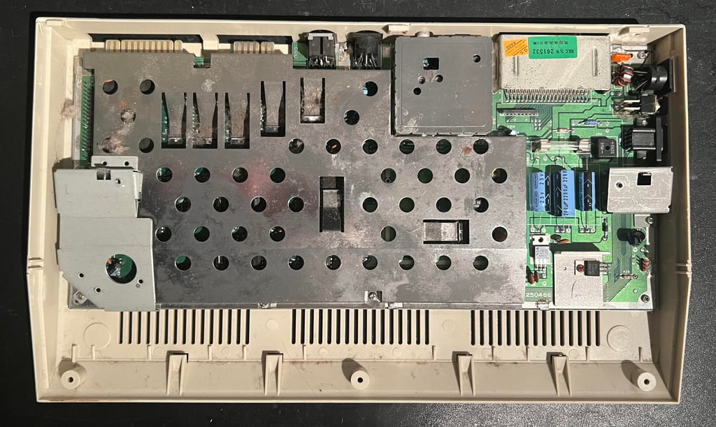
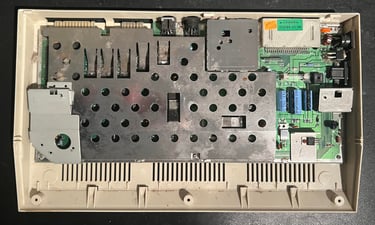
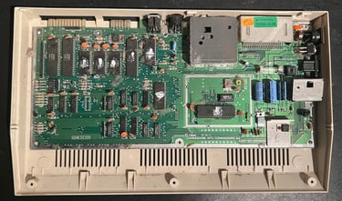
All the screws holding the RF-shield are removed. Now the complete mainboard is revealed. It is incredible dirty and dusty, lots of dried heat paste, but appears to be in good condition otherwise.

Exterior casing
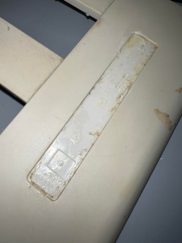
Both the top- and bottom cover are incredible dirty. There is a thick layer(s) of grease on them and in addition several dark stains and marks. And not only is the badge somewhat bent and bulged, but is only partly glued to the top cover. Before the cleaning can start both the LED and the metal badge are removed. Removing the LED is straightforward, but it it wise to be a bit careful to not break the brittle plastic. The two small plastic clips are pushed away from the LED while at the same time the LED is pulled out.

To remove the metal badge spudgers and opening tools are used to pry it off the cover while applying some hot air from a hair dryer.
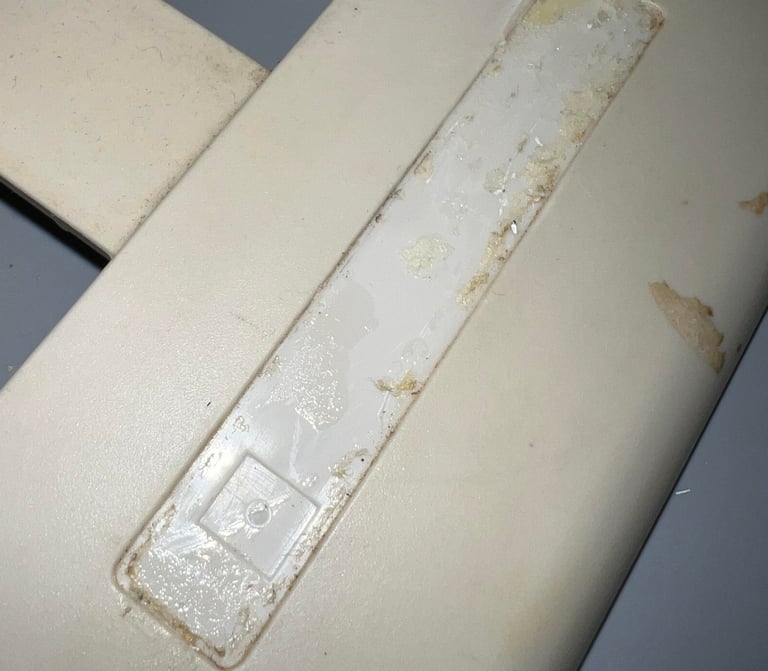
The metal badge is quite dirty and sticky on the backside. To make sure the badge can be glued back (using double sided tape) to the cover the backside needs to be clean. Therefore the badge is soaked in mild soap water for about a week. This releases most of the old glue. The remaining glue is removed with isopropanol. Finally the metal badge is flattened as good as possible. It is not 100 % flat, but I think it is good enough to be used.
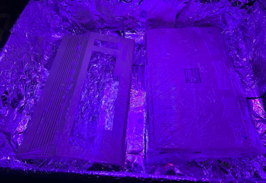
Both top- and bottom cover is soaked in mild soap water for about 48 hours. This removes the grease and fat, but the marks and stains are removed with isopropanol on a Q-tip. Then the covers are retrobrighted for about 14 hours using 12 % hydroperoxide cream which is applied regularly (about every hours). The covers are exposed to UV-light. NOTE: the rubber feets are removed before retrobrighting. This is because the rubber can become "sticky" due to the hydroperoxide. The rubber feets will be glued back afterwards.

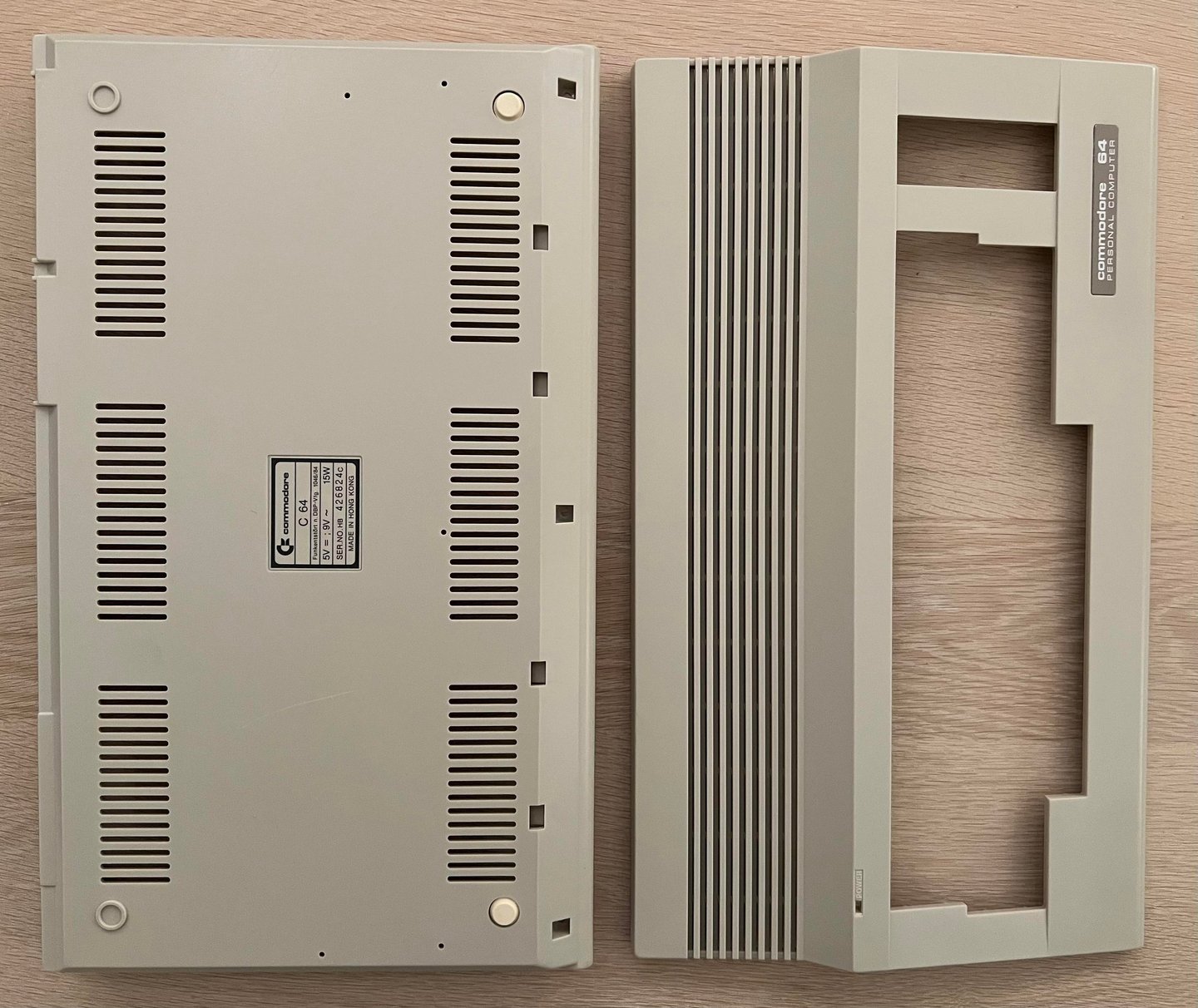
After cleaning and retrobrighting the metal badge and rubber feets are put back in. The result is very nice I think! See picture below.
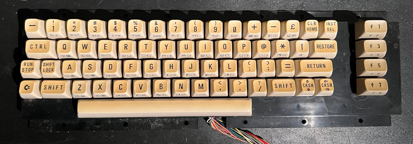
Keyboard
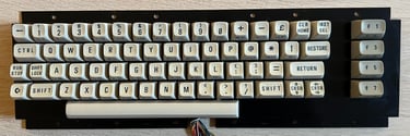
As previously mentioned the keyboard is severely yellowed. But besides that it looks to be in ok condition from the outside.

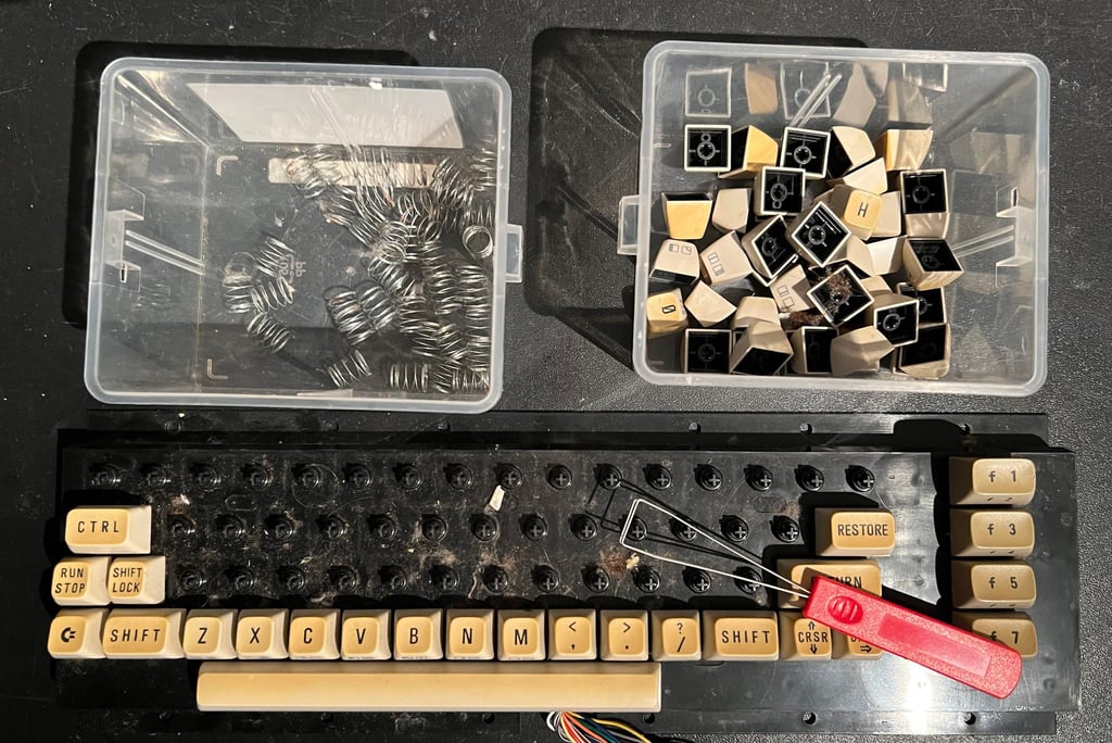
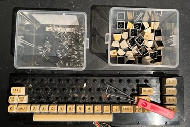
First all keys are removed using a keycap puller. It is wise to use this kind of tool to reduce the risk of damaging both plungers and keycaps. Note that beneath each keycap there is a spring, and beneath the spacebar the spring is a bit larger than the rest - so keep the spacebar spring in a separate bag to avoid mixup.
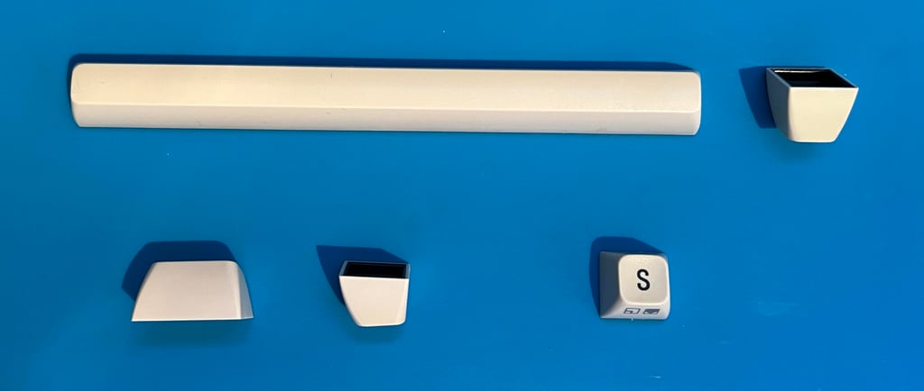
The keyboard is flipped over and the two wires connected to the SHIFT-LOCK are desoldered. Then the SHIFT-LOCK key is pressed from the backside of the keyboard toward the front. This will make the SHIFT-LOCK key pop-out of the plastic holder.

When starting to removed all the small screws at the backside I notice that one of the screws are completely rusted. I guess this is because its been behind the transparent tape, and that a small pocket of moist has startet the corrosion. With a pair of pliers the screw is removed. During the operation of the wires break from the keyboard, this needs to be repaired later.

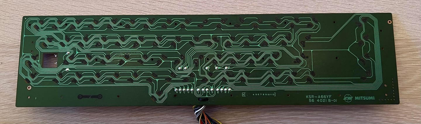
This is a MITSUMI KSR-A66YF keyboard PCB which is very common to find in the Commodore 64. First, the broken wire is repaired by soldering it back to the PCB, then the PCB is cleaned with some distilled water. I use this instead of isopropanol to reduce the risk of damaging the carbon pads. Below is a picture of the MITSUMI keyboard PCB after cleaning.
All of the keycaps are placed in a box filled with mild soap water for about 48 hours.
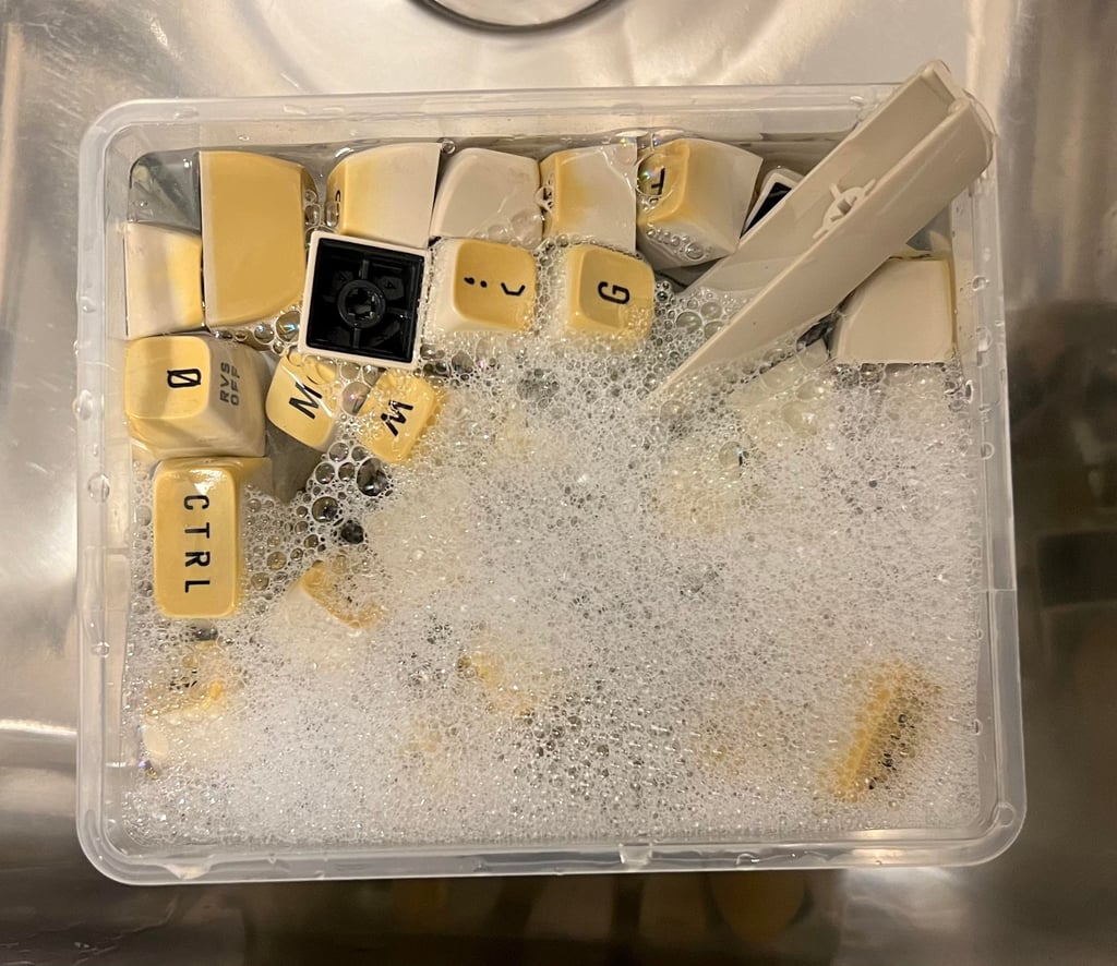

The dirt and grease are now gone from the keys, but holy moly - they are severely yellowed!

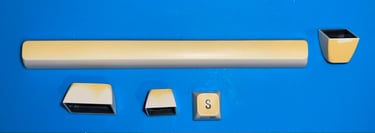
To try to remove the yellowing all the keys are placed in a plastic bag filled with 12 % hydroperoxide cream. The bag is rotated regularly so that all keys are always submerged in the liquid. This is a two week operation: the keys are submerged for one week, the cream is renewed, and the keys are submerged for another week. Below is a picture of the keys having their 12 % bath.


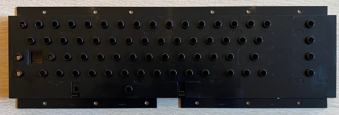
The plastic key holder is cleaned thoroughly with mild soap water. It looks as new afterwards.


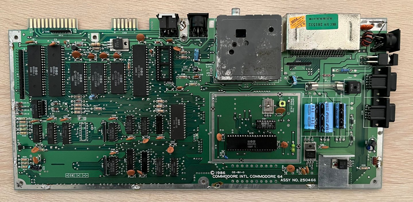
Mainboard
Assy 250566 is my favorite mainboard - no doubt! This is the same assy that I use in own C64C if that matters. There are three main reasons for this:
1) Latest revision of PCB with the "old" SID chip .This is the MOS6581R4AR version of the chip where R4 means revision 4 and AR stands for "Advanced Resonance". So, even if the "new" SID chip is good there is just something with the "old" one...
2) Contains the VIC-II chip MOS6569R5. This version of the VIC-II chip is acclaimed for showing very few artifacts such as vertical lines and checkerboard patterns).
3) Latest revision of the ROM Kernal 901227-03.
4) Few DRAM chips. Only 2 x 32 kByte DRAM chips instead of 8 x 64 kbit DRAM chips.
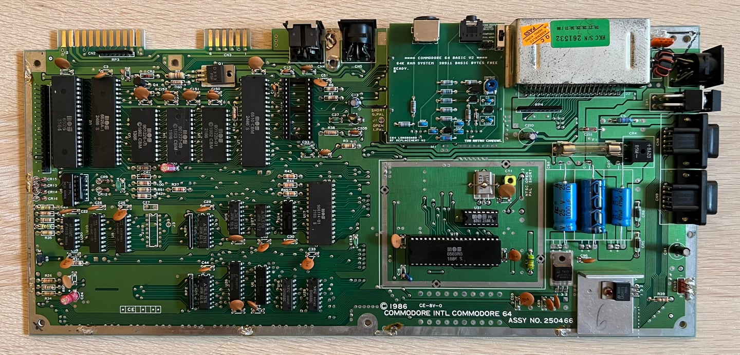
Visual inspection
Even if there is plenty of dirt and grease on the mainboard it looks to be in good condition. I can not see any signs of damage or corrosion. Also, I can not see any signs of rework. In the table below the main chips are listed (before refurbishment - some may be changed during repair if required).
Initial testing
So, does it work right away? Before testing the machine a quick check for short circuit on the +5VDC and 9VAC line at the user port is done with the multimeter in continuity mode (see the HOWTO article on measuring the Commodore 64 voltages for the position of these voltages at the user port). No short circuit is detected, so it should be safe (?) to power on.
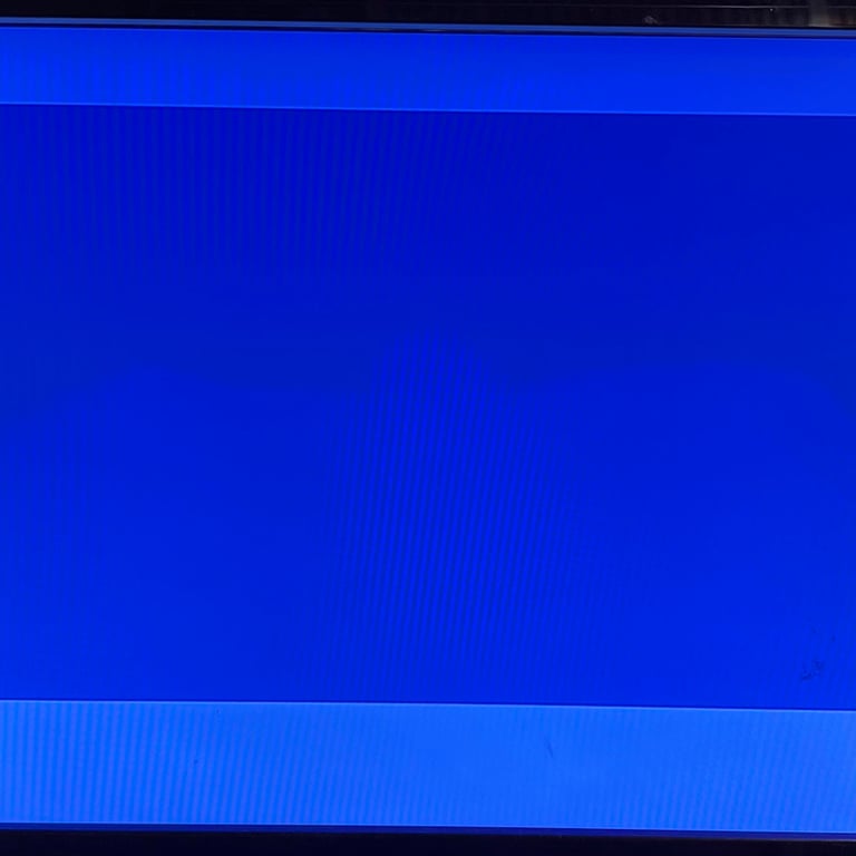
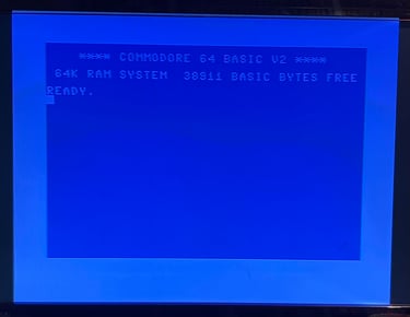
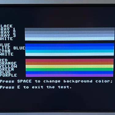
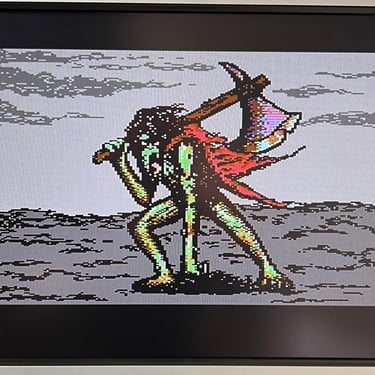
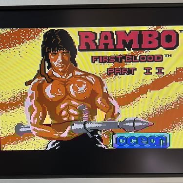
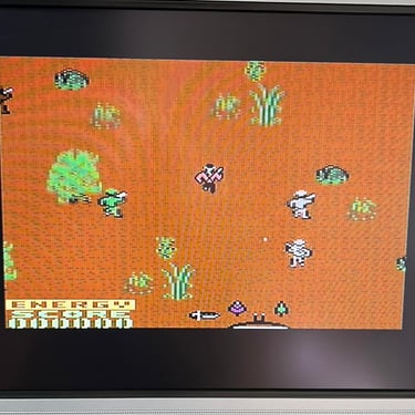
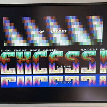
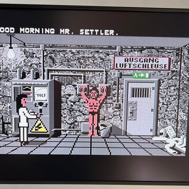
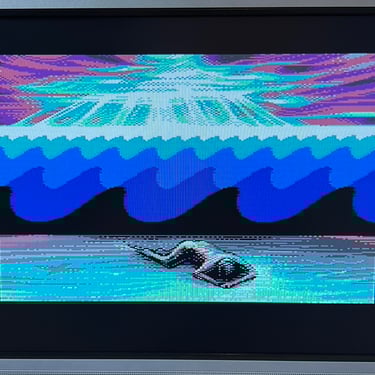
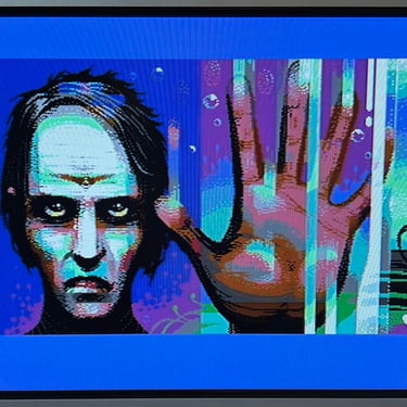
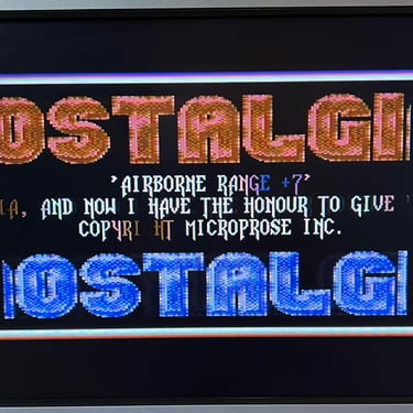
The result is: A BLUE SCREEN WITH BORDERS ONLY. Or... eh... wait... a BLACK SCREEN? Or... A BLUE SCREEN WITH UPPERCASE TEXT WITH NO CURSOR? No... LOWERCASE TEXT WITH NO CURSOR. What is happening?! The result seems to vary beetween every power on. Below are some pictures from the initial testing (except for the black screen which is only black).
Checking the voltages
Even if it seems like the voltages are present it is good practice to measure - and verify that all voltages are present and within acceptable tolerances. As the table below shows all voltages are ok. Note that this table will be updated after refurbishment.
Dead test cartridge
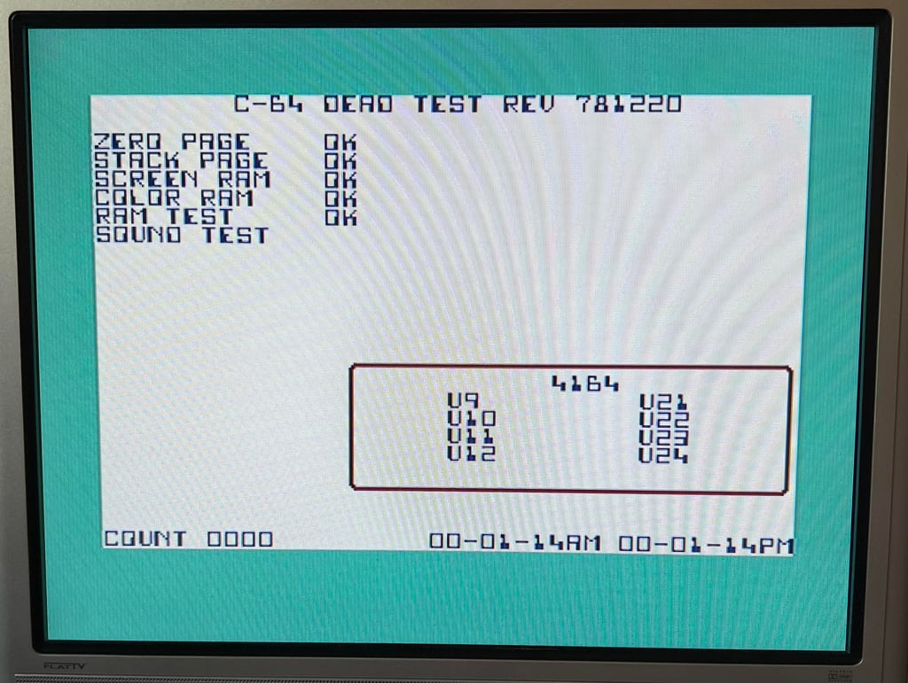
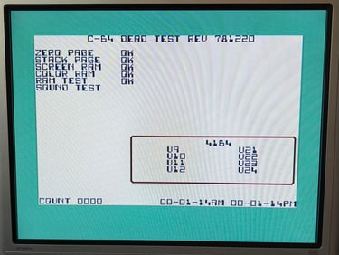
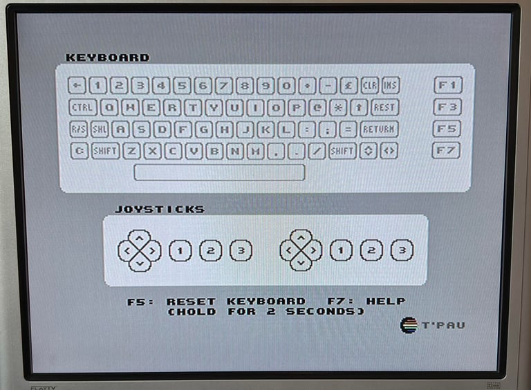
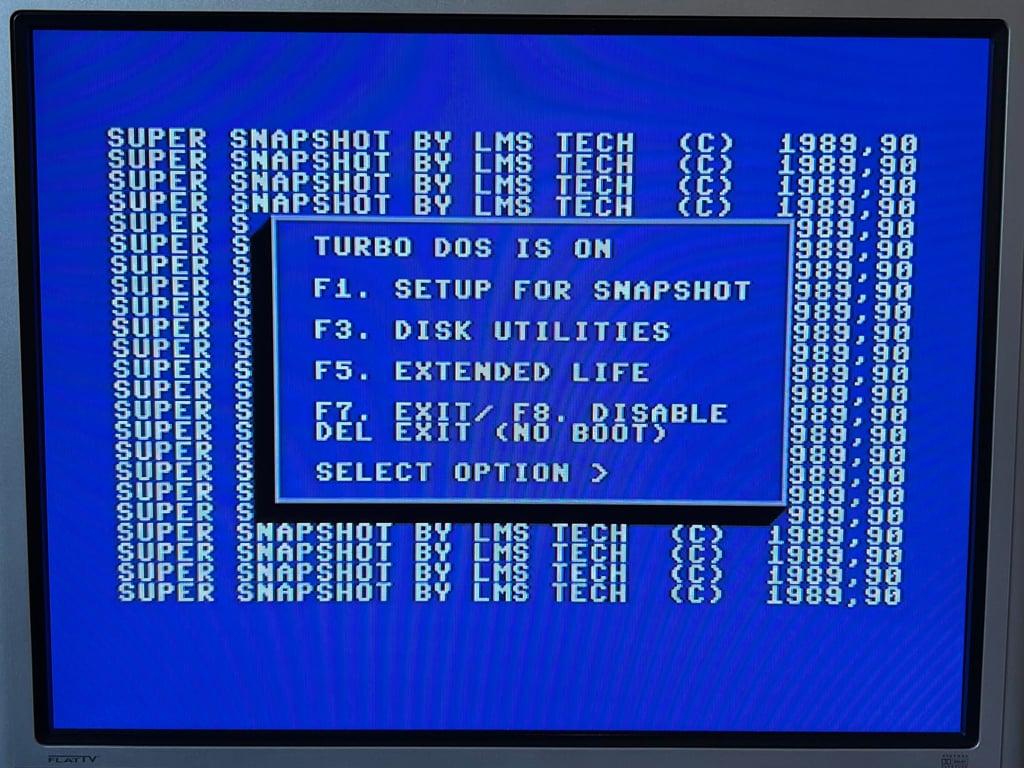
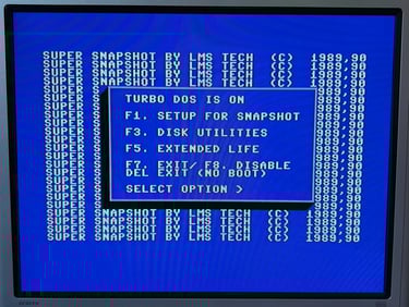
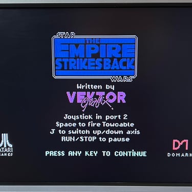
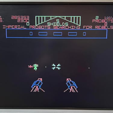
When having a fault the dead test cartridge can be very useful. As long as the CPU, PLA and VIC-II are working the cartridge can boot (in theory). Of course, if some of the glue logic are broken this isn´t always the case. And the dead test cartridge do give a very interesting clue. See screenshot below.
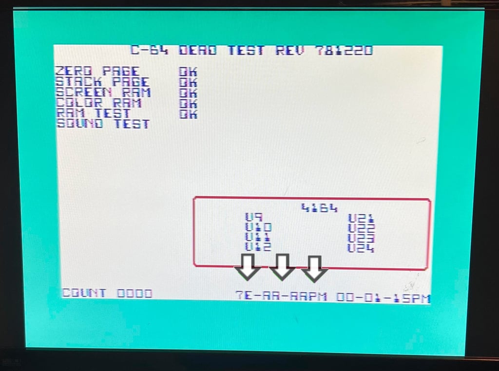
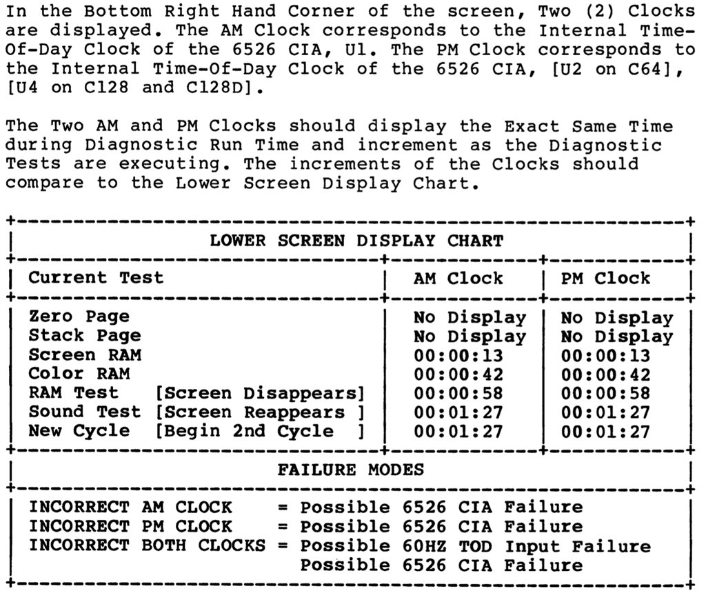
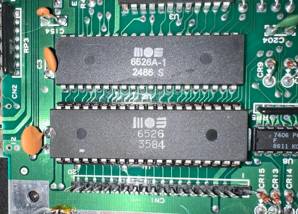
According to the diagnostics manual for the Dead Test Cartridge the AM clock on the left side on the bottom row represents the MOS 6526 CIA #1 IC. See extract from the diagnostics manual below. NOTE: It looks like it says "PM" on both clocks. But that is wrong. The left clock should say "AM" so is there something wrong with CIA #1?

Replacing the MOS 6526 CIA #1
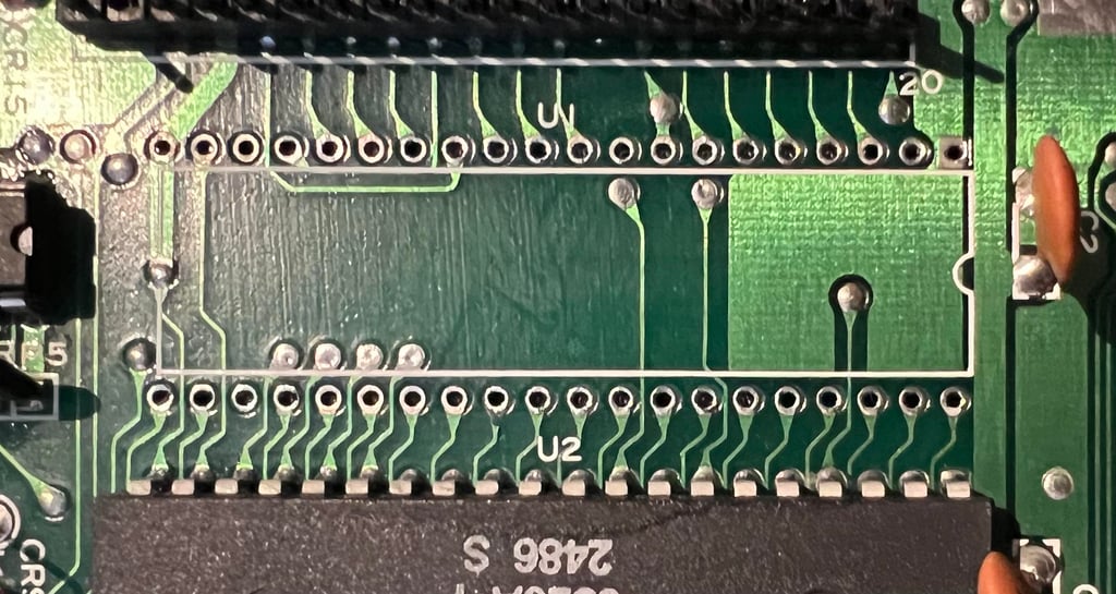
Following the lead from the Dead Test Cartridge the MOS 6526 CIA #1 (U1) is desoldered and a socket installed. No traces or pads were lifted during desoldering.

A known working MOS 6526 is installed in the socket (this CIA is taken from C64 ser. no. 828599).

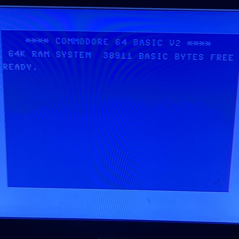
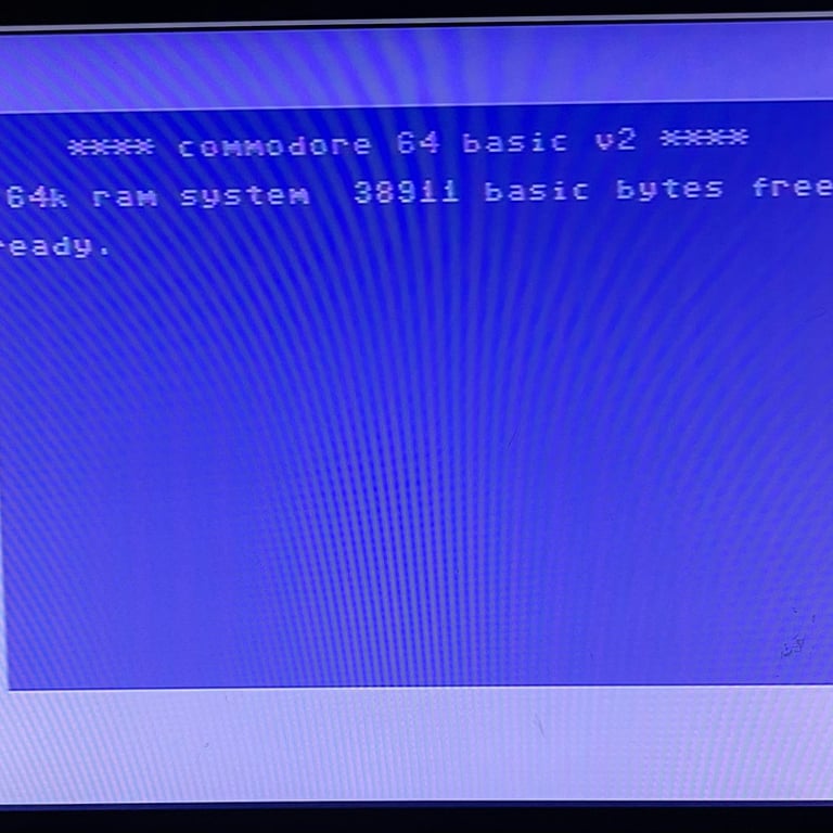
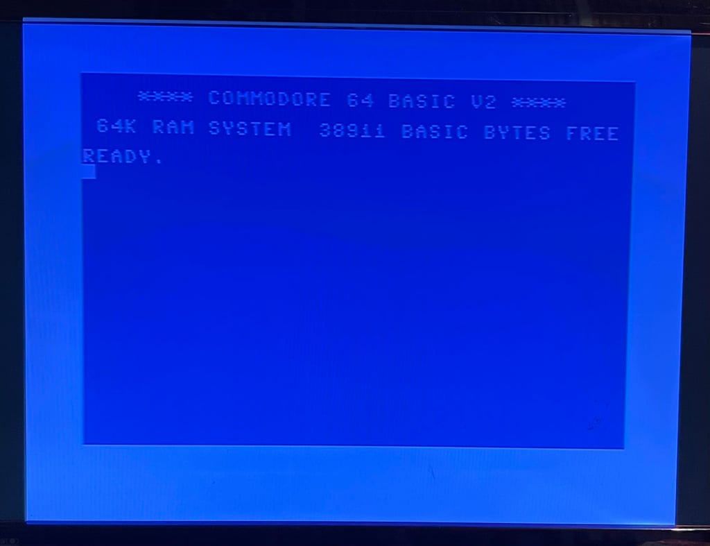
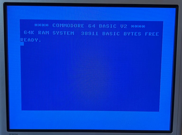
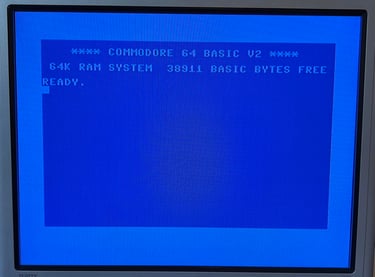
And the result is... SUCCESS! The good old blue boot screen appears with a flashing cursor and 38911 BASIC BYTES FREE.
Cleaning the mainboard
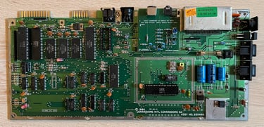
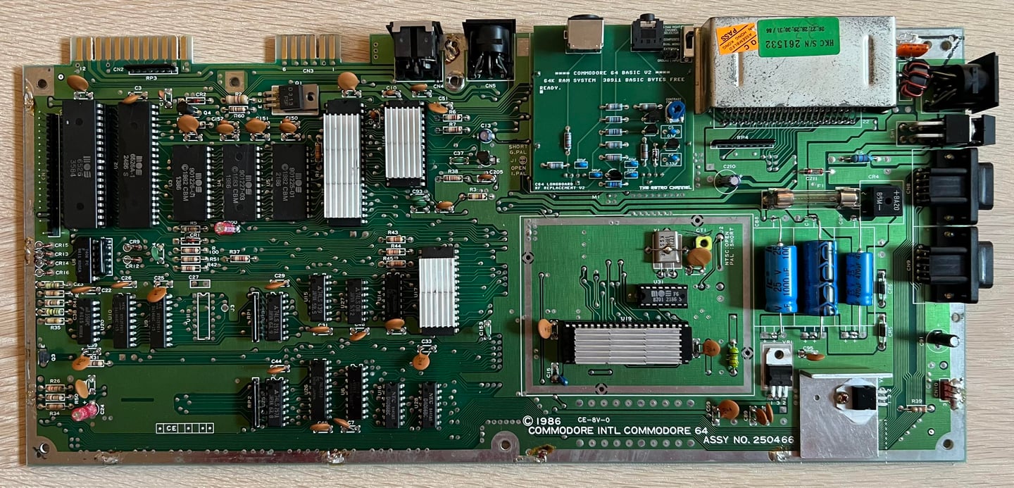
Before doing any work on the mainboard it needs to be cleaning. It is so dirty that it is even not healthy do to anything before it is properly washed. The mainboard is cleaned with plenty of luke warm water and mild dishwasher soap. Before cleaning all socketed ICs (such as the VIC- and SID chip) and the fuse are removed. Below is a picture of the mainboard after cleaning (looks much better now). Note that the SID chip is not put back yet since initial testing will be done without this installed.
Replacing the RF-modulator
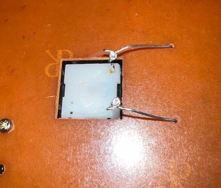
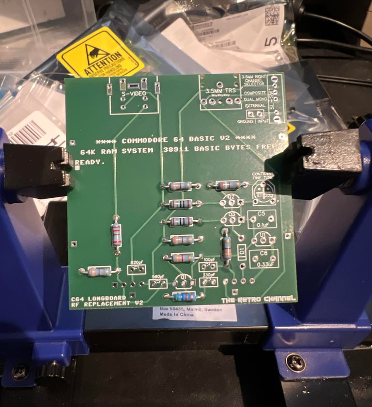
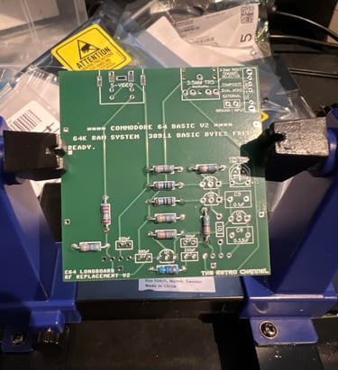
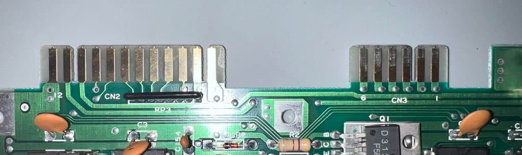
There is a new modern replacement for the old RF-modulator: C64 Longboard RF replacement V2 designed by The Retro Channel. This will be used in this machine, but first the old RF-modulator needs to be desoldered.
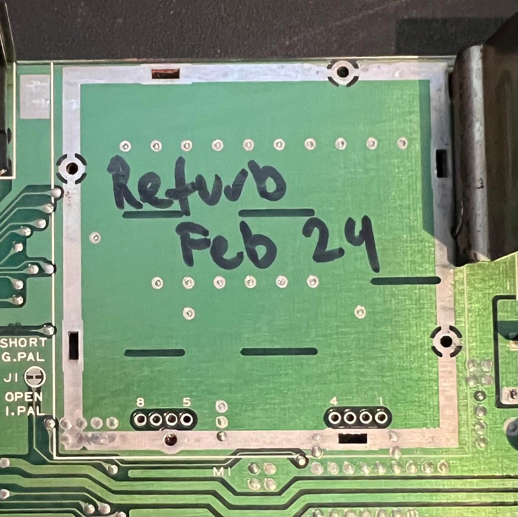
Desoldering the RF-modulator is not trivial. It is important to be both careful and patient to make sure no damage is made either to the mainboard or the RF-modulator. A detailed description can be found in the HOWTO article "Desolder the RF-modulator". The desoldering is a success - no traces or pads were lifted. See picture below.

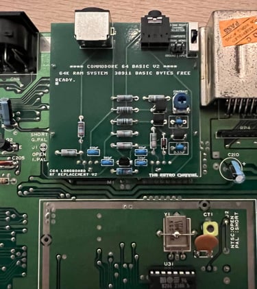
To get the best analog video picture the RF-modulator is replaced with the C64 Longboard RF replacement V2 from The Retro Channel. This is a DIY project where all the information can be found on The Retro Channels GitHub page. Pre-built replacements can be bought from The Retro Channels Tindie store, but for this machine I have built them myself. PCBs are ordered from PCB Way and components from Mouser.

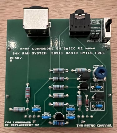
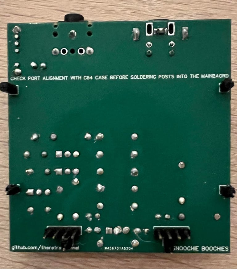
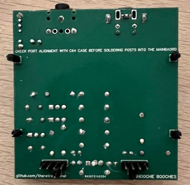
The new RF-modulator replacement is soldered back on the mainboard.

To see how this RF-replacement works and operates please check out this video from The Retro Channel - see link below.

Replacing the electrolytic capacitors
After almost 40 years electrolytic capacitors can have dried up or leaked. Although I can´t see any signs of leakage and damage on the electrolytic capacitors it is good practice to replace these with modern capacitors. The complete list of electrolytic capacitors required for the Assy 250466 mainboard can be found in the library - capacitor list.
No pads or traces were lifted during the desoldering / soldering process. In the picture below the mainboard is shown with the new electrolytic capacitors.
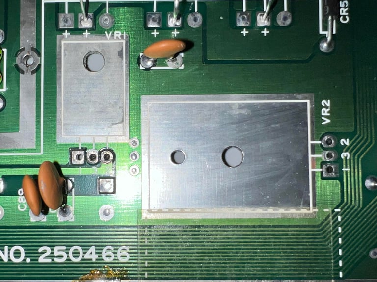
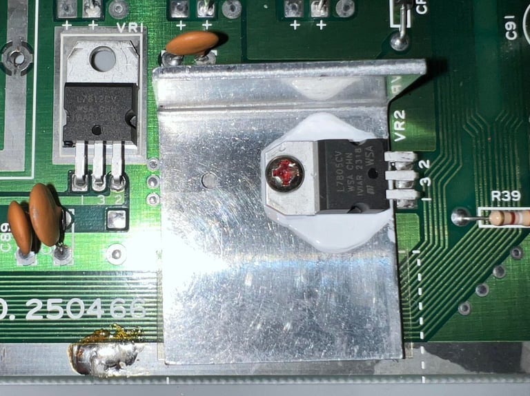
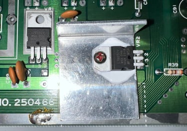
Replacing the voltage regulators
There are two voltage regulators on the mainboard: one 7805 (VR2) for the 5 VDC and one 7812 (VR1) for the 12 VDC. Both of these run very hot, but it is only the 7805 regulator which is mounted on a heatsink. The 7812 is floating on the mainboard (this is normal for all Commodore 64 machines). It is easy to get new modern 7805/7812 regulators so it is good practice to replace these as part of the refurbish. A small blob of thermal paste is placed beneath the heatsink and the 7805.
In the pictures below both the desoldering of the old voltage regulators and the newly installed regulators are shown.

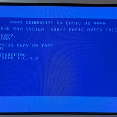
Cleaning the user- and datasette port
After almost 40 years chances are that the user- and datasette ports are oxidized and covered with grease. This can prevent the Commodore 64 from e.g. loading your favourite game from tape. To revive the ports they are "scrubbed" with a rubber eraser. This is a gentle way of removing most of the grease and revive the plating. Finally the pads on the ports are cleaned with some isopropanol.


