

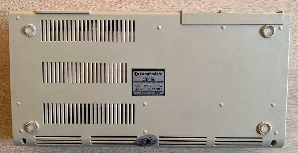
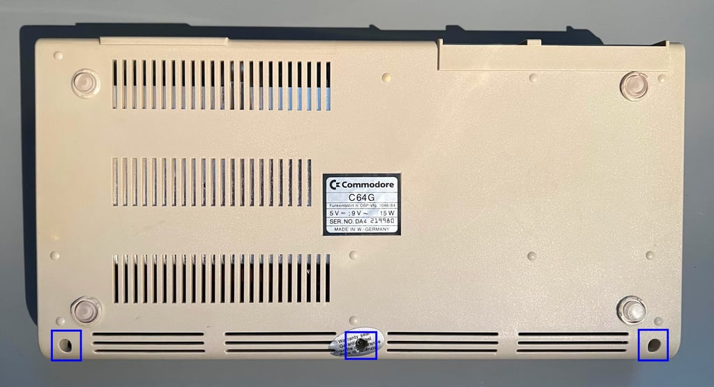
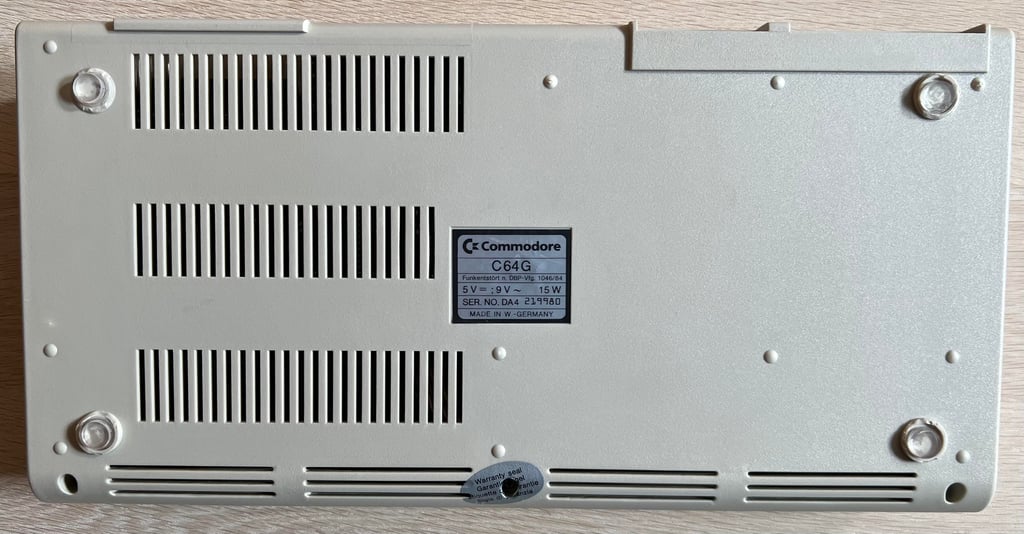
C64G [PAL]
Ser. No. 219980
Assy 250469
Artwork 252311 (REV B)
Starting point
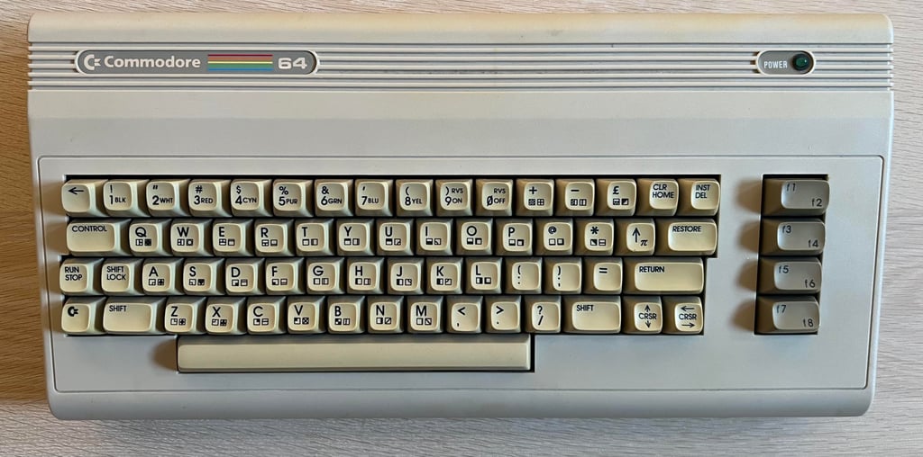
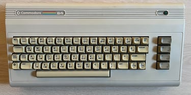
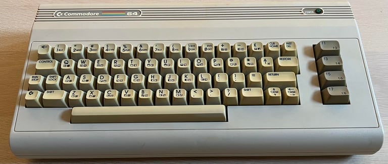
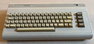
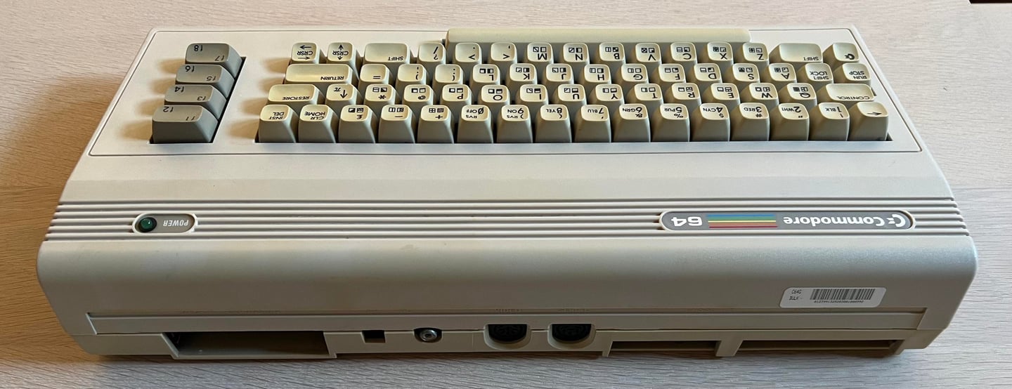
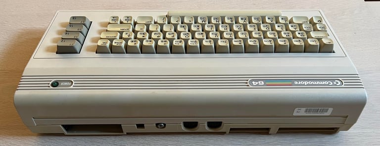
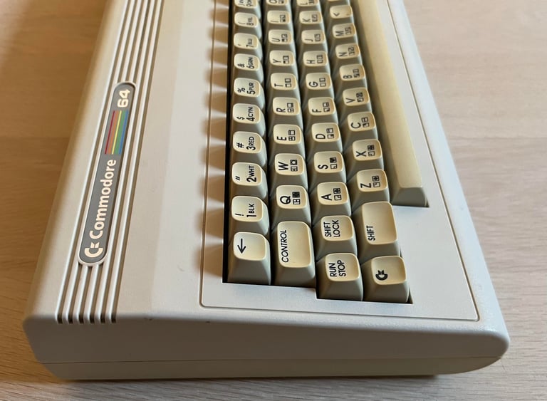
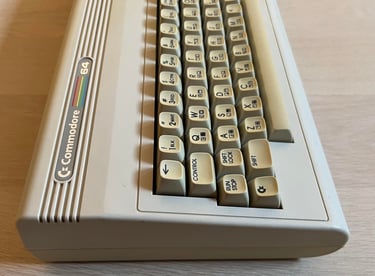
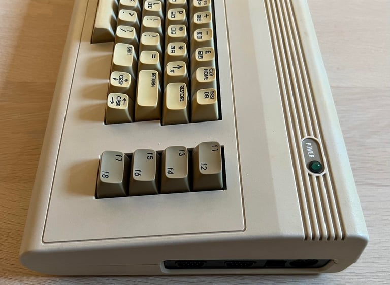
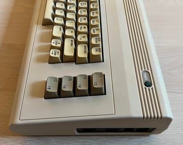
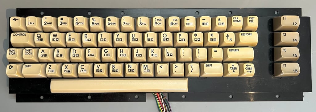
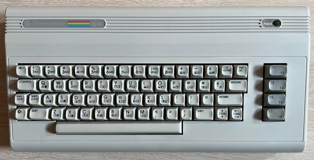
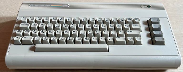
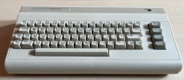
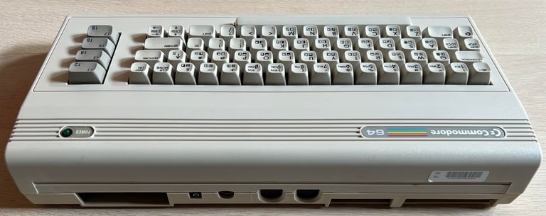
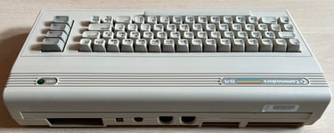
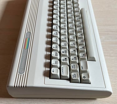
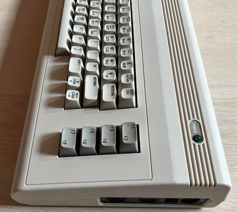
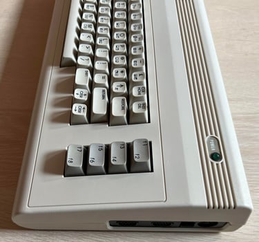
This fine looking, and fully functioning, C6G is in for a RF-modulator replacement and some tender, love and care. From the outside the machine looks to be in very good condition. There are some dirt and grease, but other from that I can not see any damage. I notice that the "K" keycap requires a bit more force to be pushed down compared to the other key. Also, the keycaps are quite yellowed so I think that some retrobrighting will be required.
As mentioned the main reason for this refurbish is to replace the old RF-modulator with the modern RF-replacement V2 designed by The Retro Channel.
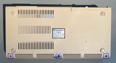
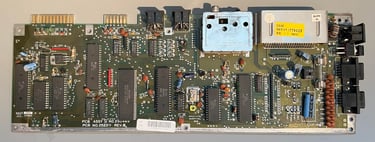
Below are some pictures before the refurbishment.
Refurbishment plan
The refurbishment plan for this C64G (order can vary and some of the tasks will be done in parallell):
- Clean and remove stains from the chassis
- Clean and restore the keyboard
- Retrobright covers and keycaps
- Refurbish main board (cleaning, checking, repairing, replacing capacitors etc.)
- Replace the RF-modulator with C64 Shortboard RF replacement V2
- Verify operation by testing
The plan can be updated during the refurbishment process. Sometimes I discover areas that needs special attention.
Opens it up...
To open the C64G is like open a standard Commodore 64 breadbin. The three screws are removed from the bottom cover.
The top cover is lifted about 30 degrees while carefully wobbling the three plastic clips at the back. This will separate the top from the bottom cover - hopefully without damaging the plastic clips. Luckily, it seems that the three plastic clips are undamaged. The interior looks very nice - some dust, but otherwise in great condition.

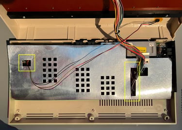
Both the LED and keyboard connector are removed from the mainboard. Then the RF-cardboard shield is removed and the mainboard is revealed.
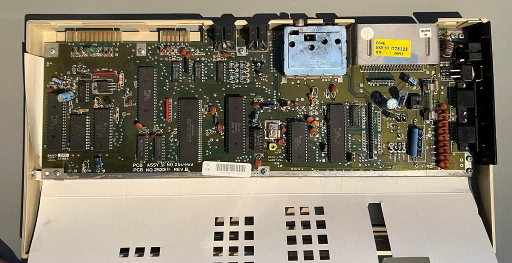
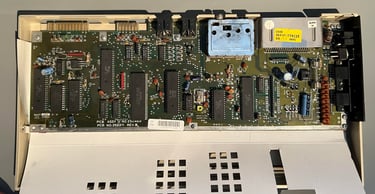
The mainboard looks to be in good condition. There is quite some dust and grease, but no sign of any damage or severe corrosion. To remove the mainboard from the bottom cover all the nine screws are removed.
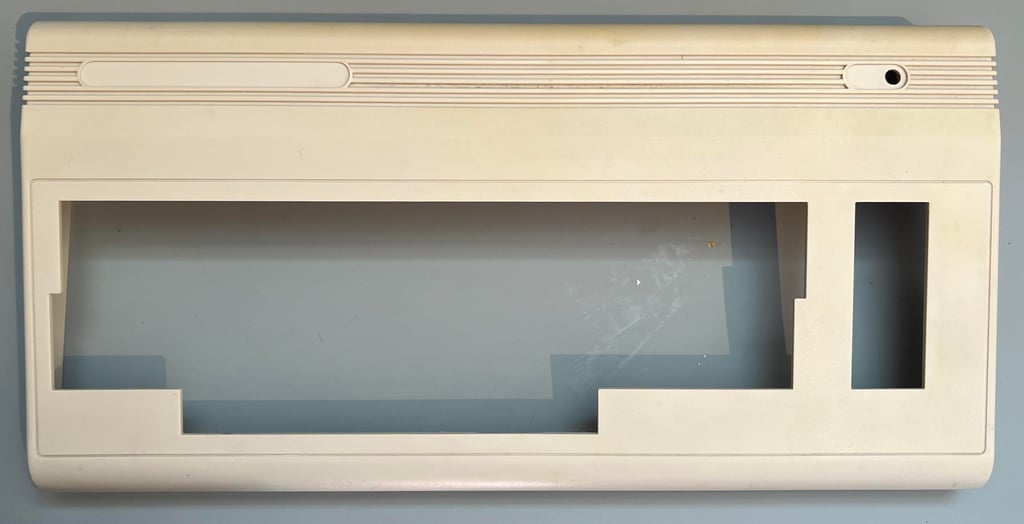
Exterior casing
The covers need a thorough cleaning, but there are no signs of any damage as far as I can see. Also, the plan is to retrobright the covers which means that they need to be free from any grease and fat before retrobrighting.
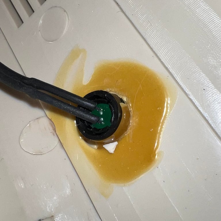
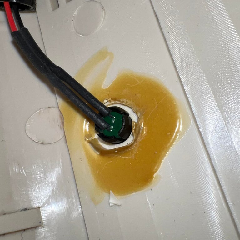
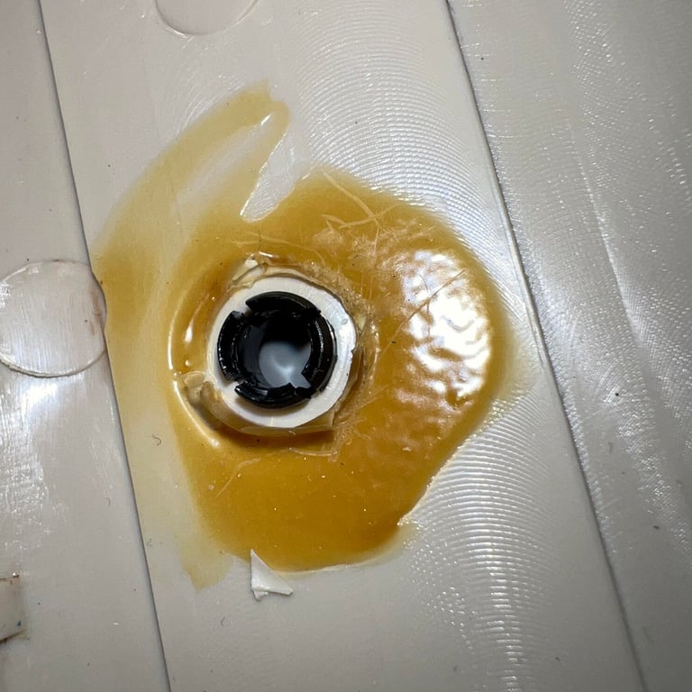
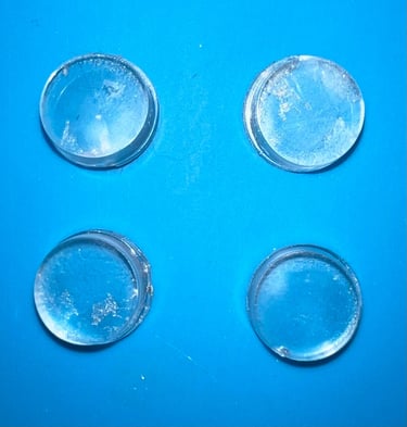
Before cleaning the covers the LED is removed. In the C64G there are some glue on the plastic LED holder which is carefully removed. With the glue out of the way the plastic holder and the LED are removed (note that the LED is removed by pushing it from the outside towards the inside. See pictures below.
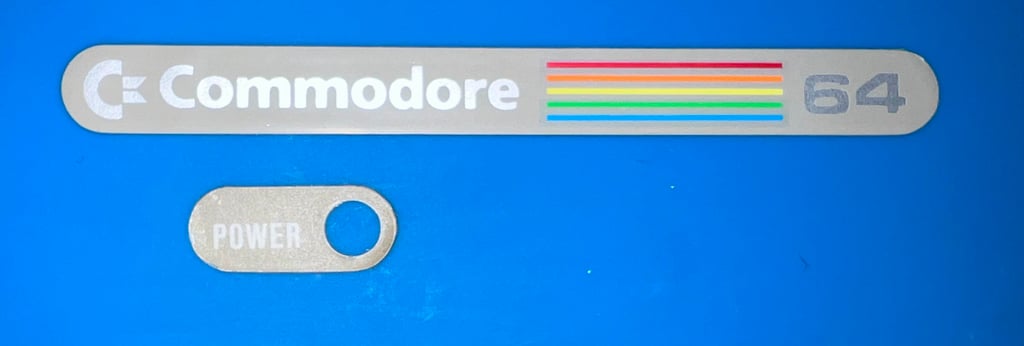
Also, the "Commodore 64" and "Power" badge are removed from the top cover before cleaning and retrobright. Although this is not strictly required it is good practice to do this.


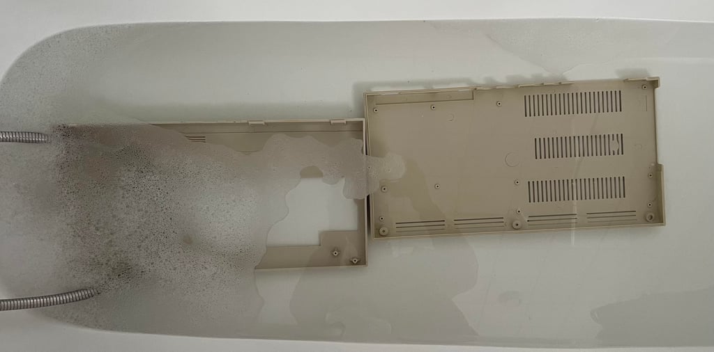
Both top- and bottom covers are soaked in mild soap water for about 24 hours. This will remove most of the dust and grease.

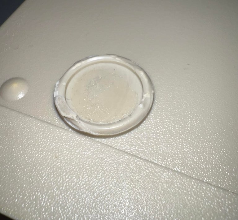
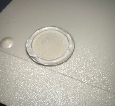
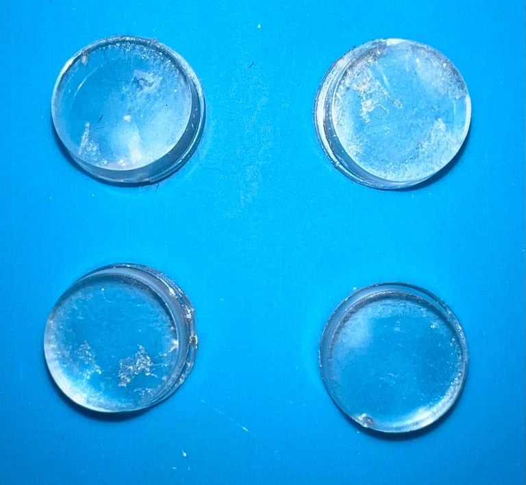
Before retrobrighting the top- and bottom cover the four rubber feet are removed. The reason for this is that the rubber often reacts with the hydroperoxide cream making the feet very soft and sticky. Now I notice that the rubber feets are probably installed at a later time. The circular area surround the feets are partly chipped off.
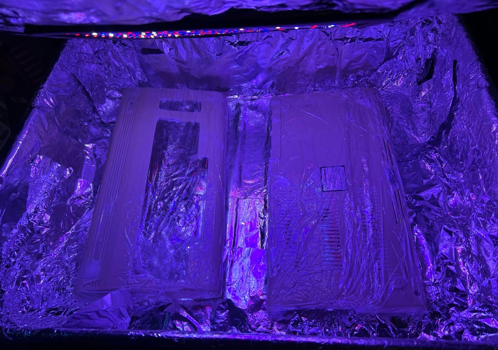
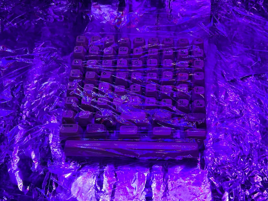
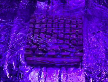
The top- and bottom cover are retrobrighted for about 12 hours. This is done by applying 12 % hydroperoxide cream on the covers and wrap with plastic film. Then the covers are placed in a large plastic box and exposed for UV light. About every hour more hydroperoxide cream is added on the covers with a soft paint brush.

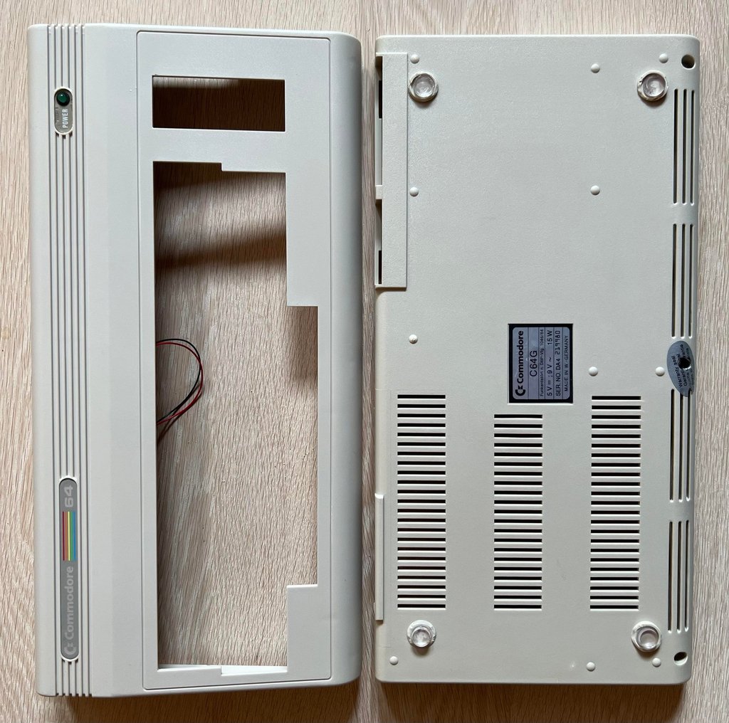
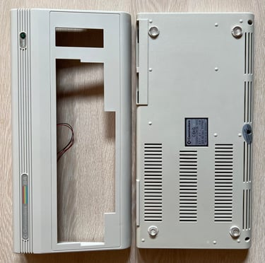
After retrobright, cleaning and re-assembling the labels the covers looks like new (!). I am very happy with the result.
Keyboard
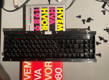
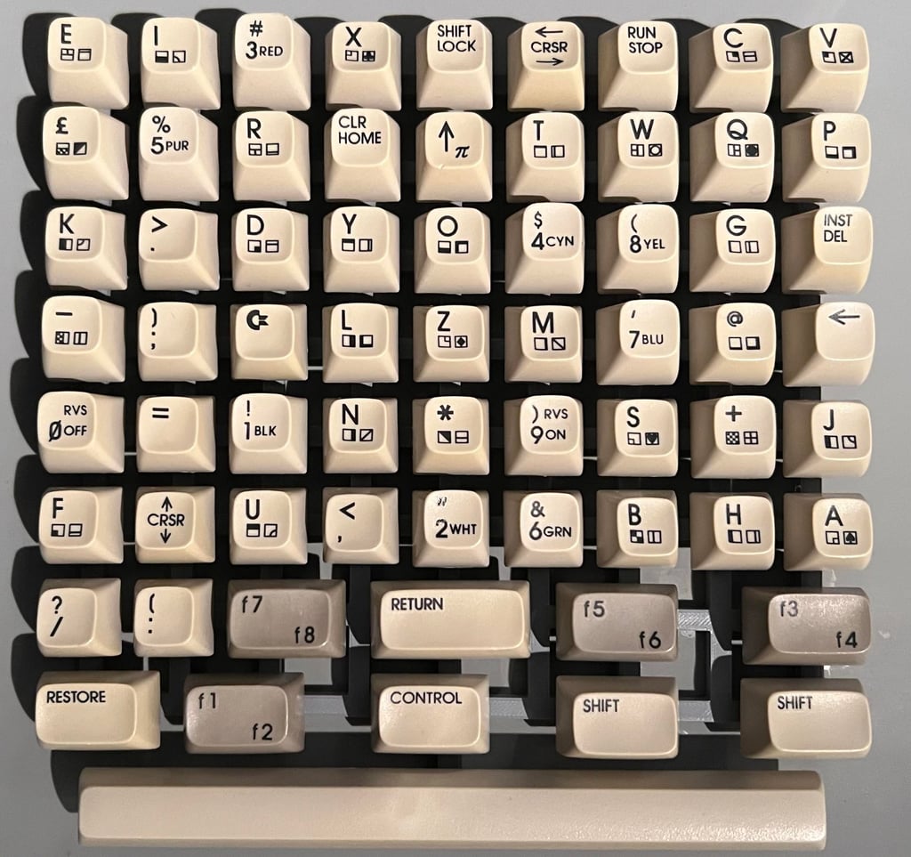
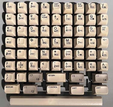
The keyboard is in good condition which is quite uncommon on these old machines. Yes, the keycaps are quite yellowed which is normal, but the amount of dust and grease are very small compared to other machines I have refurbished. As mentioned previously there is something odd with the "K" key. You need to apply more force in order to push it compared to the rest of the keycaps. Below is a picture of the keyboard before cleaning and retrobrighting.
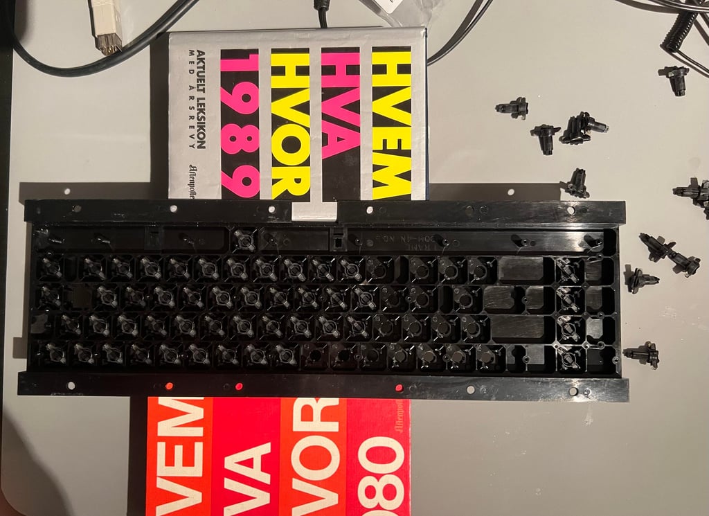
First, all the keycaps are removed. To do this a keycap puller is used. This is the most gentle way to remove the keycaps and reduce the risk of damaging either the plungers or the keycaps themselves.
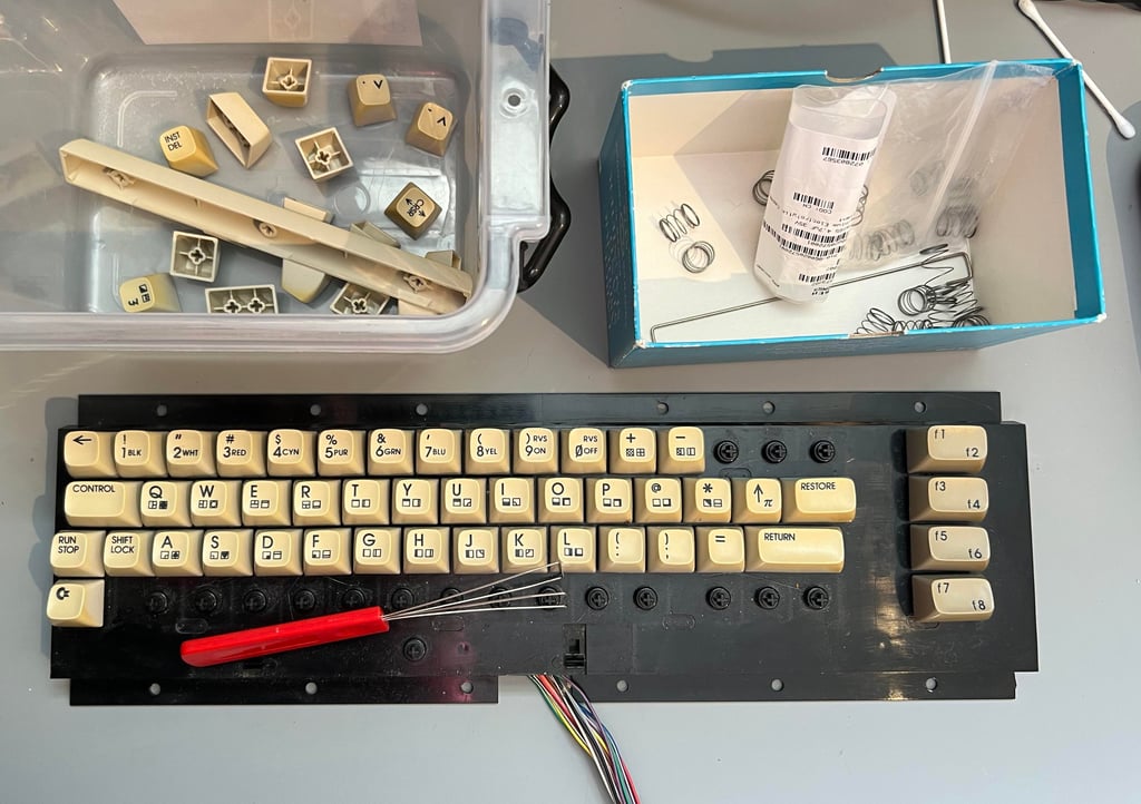

Normally there is a larger spring beneath the spacebar key, but this is not the case here. This makes me think that this spring is used on some of the other keycaps. Perhaps the "K" key?
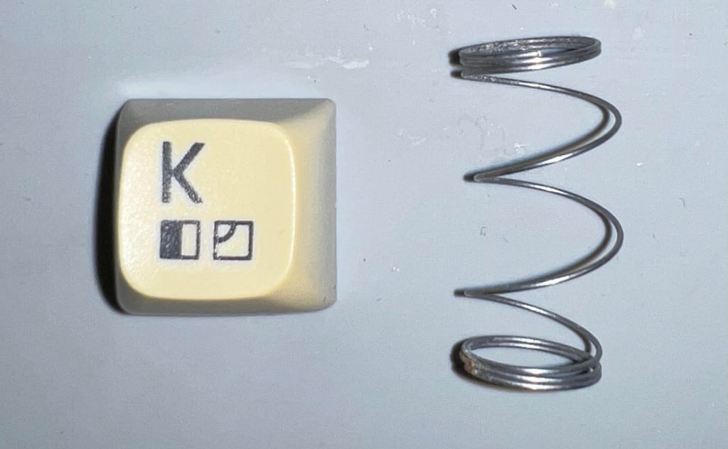
It turns out that the spring beneath the "K" key is different. But I am not really sure what is going on? The spring is severely out of shape. I will see if I can fix this - if not I will simply replace it with a new spring. And I need to see if I can manage to find the larger spring for the spacebar.

The keyboard PCB is removed. To do this all the small screws are removed, and the two wires connected to the SHIFT-LOCK are desoldered. Note: to remove the SHIFT-LOCK apply a firm push from the backside of the keyboard towards the front. The SHIFT-LOCK will pop ut quite easily.

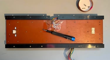
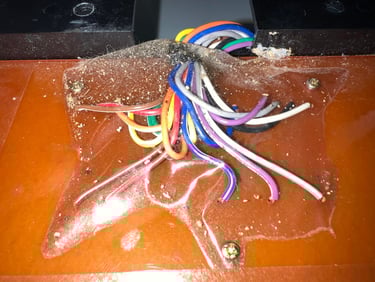
There is quite some dirt beneath the tape. This can accumulate moisture over time which results in corrosion on either the screws and keyboard PCB. So a preventive measure the tape is removed.

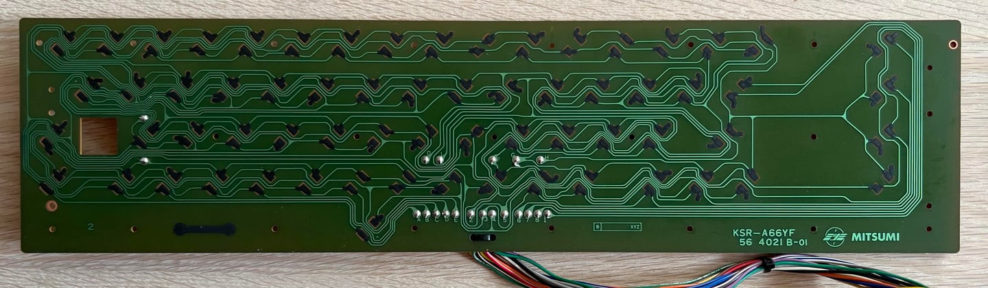
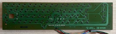
The keyboard PCB is a standard Mitsumi KSR-A66YF with carbon pads. And since this PCB use carbon pads I only use distilled water (not isopropanol) to clean the PCB. There are no signs of corrosion on the PCB which means that no moisture has affected the PCB.
All the keycaps are soaked in mild soap water for about 48 hours. This will remove most of the dust and grease from the keycaps which is very important before retrobrighting.
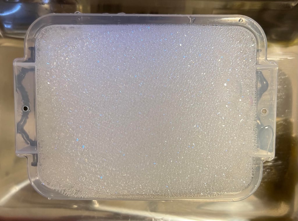
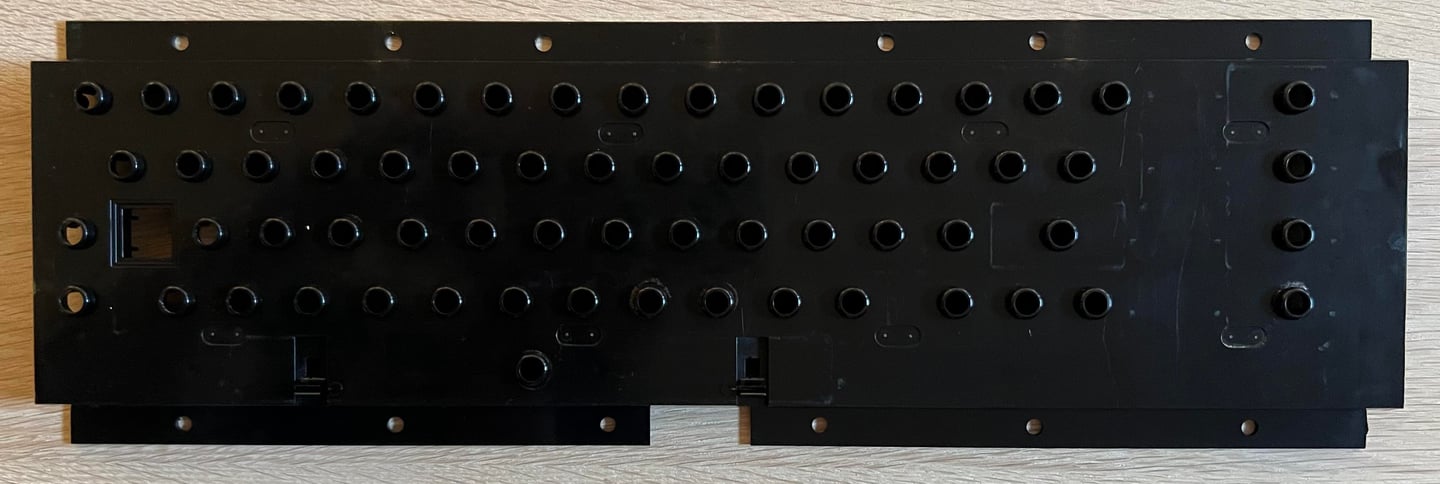
The plastic holder for the plungers is also cleaned with mild soap water. After cleaning the plastic holder looks like new (!)
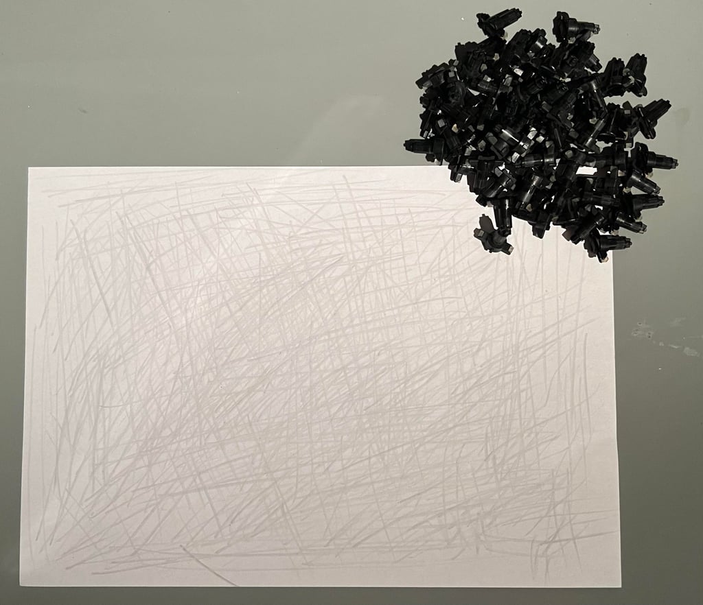
Many of us have fond memories of pushing really hard on the keys to get any respons at all. Typically keys like the RETURN and SPACEBAR requiring to be squeezed to death to make any contact. This can be fixed most of the times. The key plungers are fitted with semi-conductive rubber and quite often this rubber is polluted with grease and fat.
My way of reviving the semi-conductive rubber is to gently rub the plungers over a clean sheet of paper. This will remove most of the grease, dust and fat without risking damaging the rubber with liquids such as isopropanol. But if this gentle method does not give the expected results some small drops of isopropanol on a Q-tip can be used.

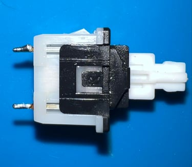
The SHIFT-LOCK key is checked for any damage and cleaned. It appears to be in fine condition and the switch is fully functional.

A little advice when assembling all the plungers in the plastic bracket is to lift it from the table with some books. This will allow some space between the tip of the plungers and the table.
The keycaps are quite yellowed, but I have seen way worse. Nevertheless, the keys are retrobrighted by placing all the keycaps in a plastic bag filled with hydroperoxide cream (12 %) and left in the bag for about a week. Note that the bag needs to be rotated from time to time to make sure the hydroperoxide cream don´t get stuck in certain areas making marble effect on the keycaps.
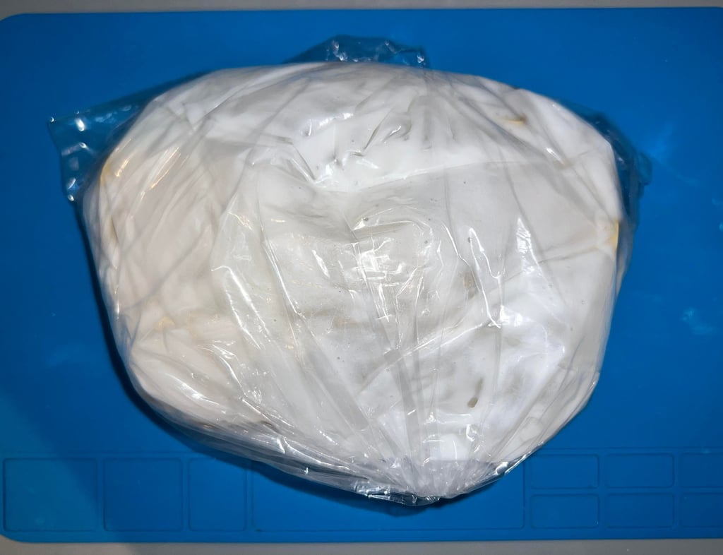
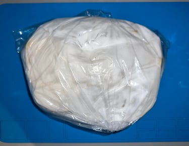
The keys looks way better after retrobrighting in the bag. But I still think that I can try to squeeze out the last bit of yellowing. So all the keycaps are placed on a mount before they are covered with 12% hydroperoxide cream and exposed for UV light for about 12 hours. In the pictures below the keycaps are shown before the final part of retrobrighting and when the keycaps are placed in the UV-chamber.
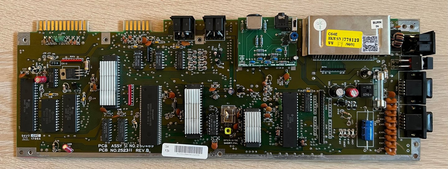
Mainboard
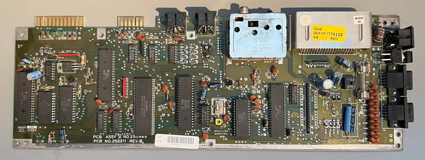
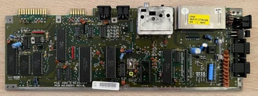
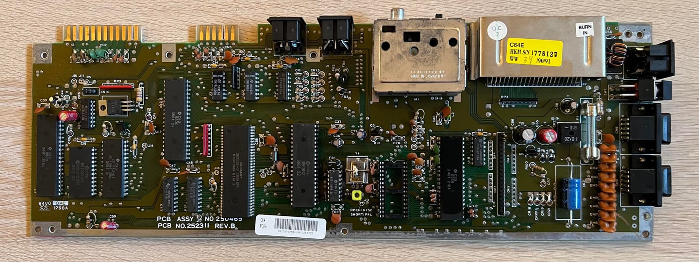
This is an Assy 250469/Artwork 252311 (Rev B) mainboard - often classified as a "shortboard" version. Compared to "longboard" typically found on C64 breadbins (but can also be found in early revisions of C64C) it differs in some areas:
64 pin Super PLA – Compared to the old 28 pin PLA this Super PLA contains in addition to PLA functionality a lot of the other glue logic.
No 12 V rail used to supply the VIC-II and SID – Compared to the old breadbin which has dedicated 7805 and 7812 voltage regulators to supply additional voltage sources.
MOS 8500 CPU – Compared to the Commodore 64 breadbin which normally use the MOS 6510 CPU (note that these chips are interchangeable so they could be used in both).
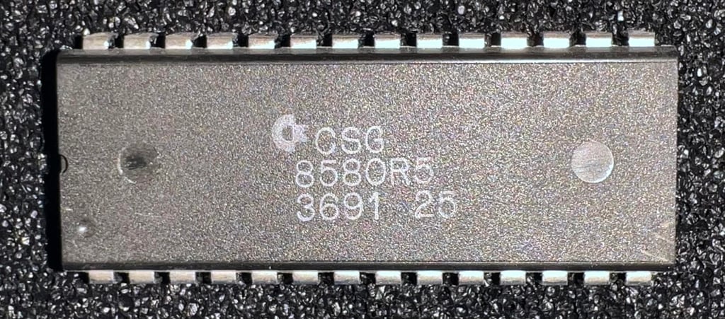
MOS 8580 SID -Compared to the breadbin which use the MOS 6581 SID. Note that these are not interchangeable since they use different voltage supplies.
MOS 8565 VIC-II – Compared to the breadbin which use the MOS 6569 VIC-II. Note that these are not interchangeable since they use different voltage supplies.
Visual inspection
Before inspecting the mainboard it is cleaned thoroughly with mild soap water and plenty of water. To make the mainboard dry faster and make sure all the water is evaporated plenty of isopropanol is used also to clean the PCB. Note: while cleaning the mainboard the main fuse and the MOS 8580 SID is removed. The former is removed since the glass fuse is not water proof and the latter is removed since it is not required for the Commodore 64 to start and is thus removed until later testing. Below are some pictures of the mainboard after cleaning.


In the table below the main chips are listed (before refurbishment - some may be changed during repair if required).
As can be seen from the table above many of the custom ICs were produced in august and september 1991. So it is a fair guess that this machine was assembled sometime autumn in 1991. Also worth mentioning is that this PLA version also includes the color RAM. These PLA ICs made by Sharp is known to be very robust compared to the notorious PLA made by MOS.
UPDATE: The machine is updated with the SuperKernal module to support floppy speeder ROM Kernals.
Checking the voltages
There is no need for any initial testing of this machine since it is known to be working. Of course, there can be issues which would be revealed during refurbish if there are any. Nevertheless, it is good practice to measure the voltages both before starting and after refurbishment. A detailed description of what the voltages represent, and where they can be measured, can be found in the article "HOWTO - Checking C64 voltages".
All voltages are present and within acceptable tolerances. See table below. This table will be updated when refurbish is complete.
NOTE: A "new" power supply was used when the voltages was measured after refurbish. With "new" I mean a modified C128 power supply which can be used to source both a C64 and C128 (not simultaneously). The voltages will be a bit lower than normal, but still within acceptable tolerances.
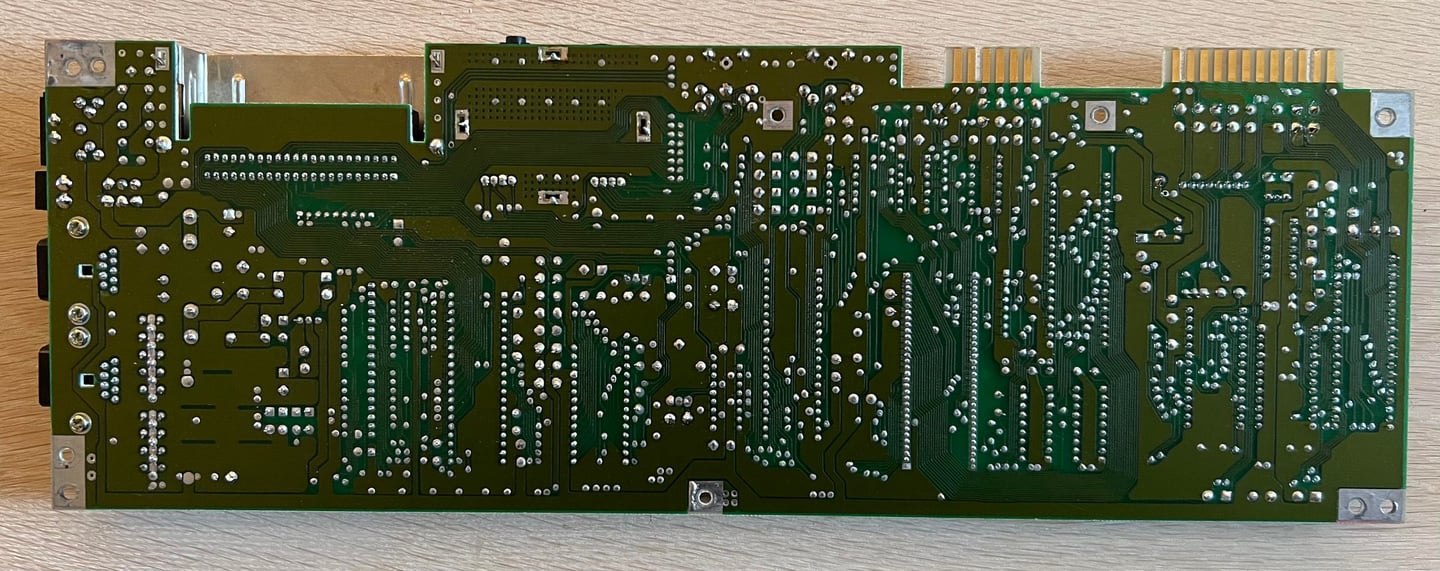
Replacing the electrolytic capacitors - mainboard
Is it strictly required to replace the electrolytic capacitors on a working Commodore 64? No. But it is good practice to do so I think. Even if they do not leak or is damaged in any way, they are soon 40 years old and is way beyond expected lifetime. So with careful desoldering to not damage any pads or traces, and replace the caps, I think the mainboard is in a better state.
According to the reference documentation there are nine electrolytic capacitors. All of these are replaced with new quality capacitors. No traces or pads were damaged in the process. Below is a picture of the mainboard with the new capacitors in place.

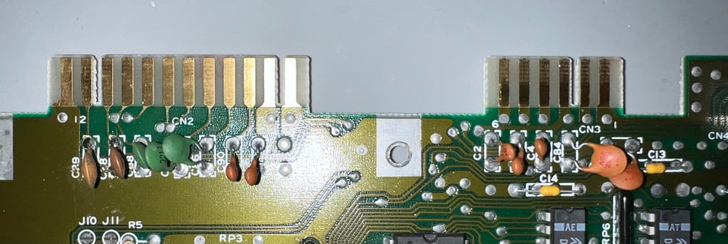
Cleaning the user- and datasette port connectors
A very simple, but often neglected, operation is to clean the user- and datasette port. These connectors are often heavily oxidized after many years and if often the culprit of the notorious "?LOAD ERROR" message. To clean these connectors is very straightforward: using a rubber eraser (yes, the one you had in school) to remove most of the grease in a gentle way. Then clean with isopropanol and a Q-tip.
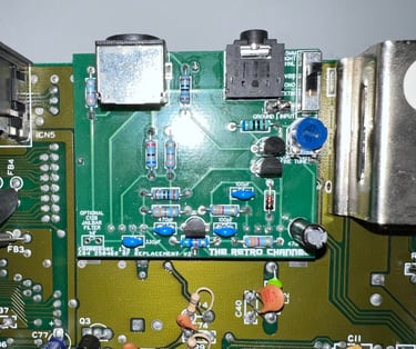
Replacing the RF-modulator
The RF-modulator is to be replaced with the latest revision (2nd) of the RF-replacement board from The Retro Channel. It claims to be the best analog RF-replacement in the market. The original Commodore (or Mitsumi) RF-modulators were based on a standard design which did not cater for different variations and tolerances from discrete components and the analog video signal from the VIC-II. The new RF-modulator replacement lets you adjust to the most optimal picture quality using a potentiometer on the PCB.
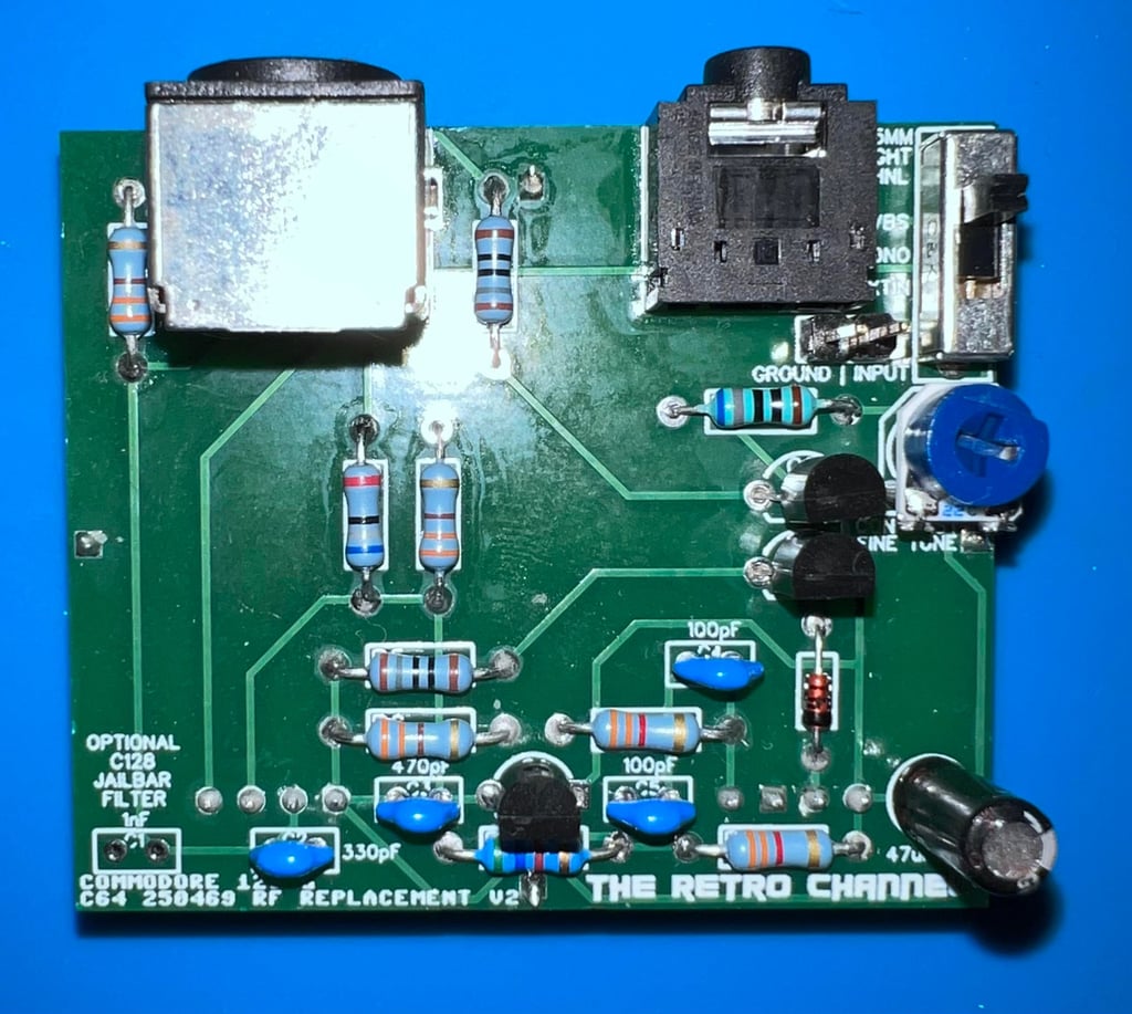
All required parts to build the RF-modulator replacement is sourced from Mouser, PCBWay and AliExpress. Below is a picture of the RF-replacement after assembly (PCBA). Note that you can the complete BOM from The Retro Channels GitHub page.

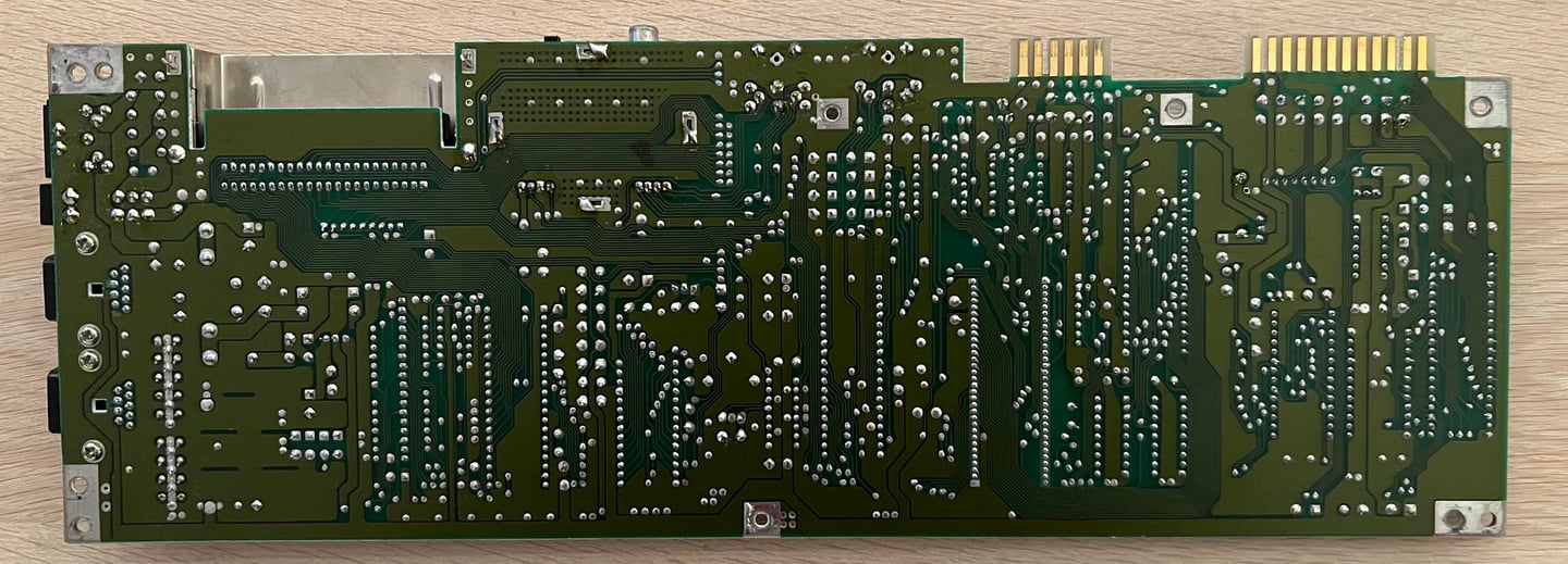
Before the RF-replacement can be installed the original RF-modulator needs to be removed. This is not rocket science, but removing this is not trivial. You need to be very careful no to damage traces or pads. The way I desolder the RF-modulator can be found in the HOWTO article "Desolder the RF modulator".
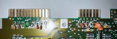
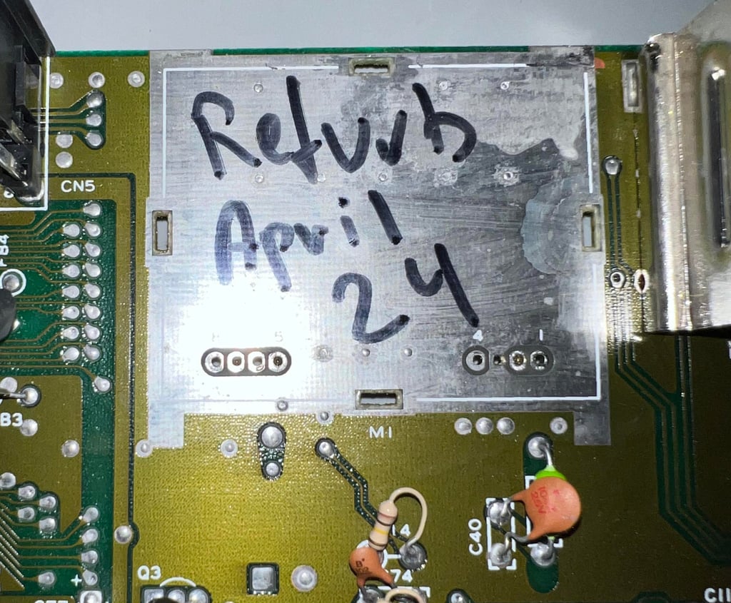
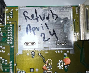
The RF-modulator is desoldered without any damage to traces or pads. See picture below.
The new RF-replacement modulator is soldered in place. See picture below. I am curious if the picture quality improves or not. I have only tested this once before I must admit that I was really struggling seeing any difference. There was some subtle differences when poking around the potentiometer, but pushing my 50 years I am struggling to see the difference...

Adding heatsinks
AC/DC´s great song "Heatseeker" from 1988 is not appropriate in the Commodore 64 context. We do not seek the heat. We sink the heat. In an attempt to reduce the amount of trapped heat in the C64 casing the cardboard RF-shield is removed. In modern age this is serves no purpose any more - it only encapsulates heat. And since too much heat can reduce the durability of custom ICs it is good practice to try to find measures to dissipate excessive heat. A simple, but effective, way of doing so is to add heatsinks to the most valuable and hot ICs; MOS 8500 CPU, MOS 8565 VIC-II and MOS 8580 SID. In the picture below the mainboard is shown with the heatsinks installed.

Interlude - Faulty LED
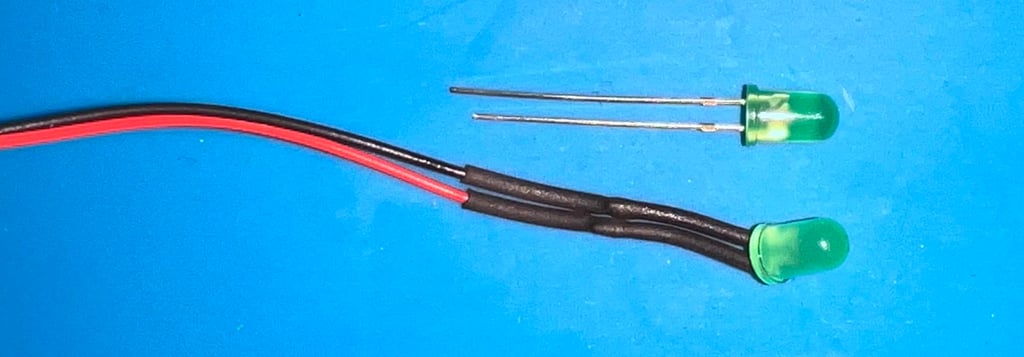
When starting testing the machine after the refurbish I notice that the LED has given up the ghost. I think that the LED was functional before the refurbishment, but I am not sure. Nevertheless, replacing the LED with a new modern is unproblematic. The new LED is probably a bit brighter than the original, but that should be fine.
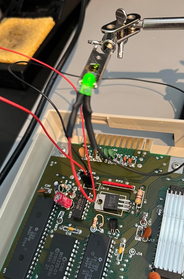
Below are some pictures of the old LED (and the new replacement LED) and from the testing of the new LED.

Testing
Proof is in the pudding - does it work?
Testing is done through two main stages:
Testing the basic functionality and chips
Testing by using the machine playing demos, games etc. accessed by both floppy and datasette to verify correct operation
Basic functionality and chips
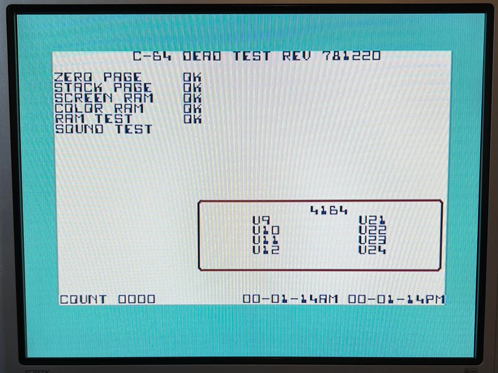
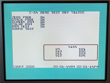
First test is done using the Dead Test Cartridge. This test doesn´t test all the functionality of the Commodore 64, but it does test the basic functionality of the major chips such as the CIA #1/2, CPU, VIC-II, PLA, RAM and SID. As the picture shows below the test is passed.
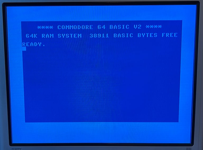
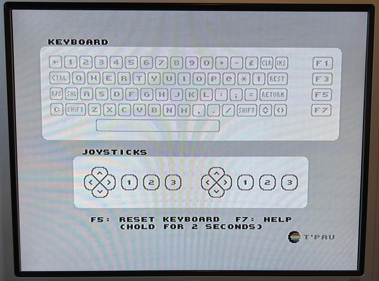
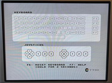
Next test is to power the Commodore 64 to the blue boot up screen and also check the keyboard to make sure all keys works as they should. The test is passed; all keys works and 38911 BASIC Bytes Free.

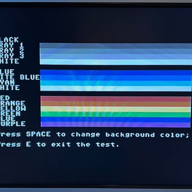
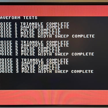
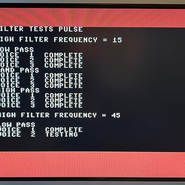
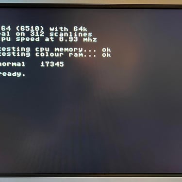
The basic functions of the VIC-II, SID and RAM is tested with 64 Doctor, Commodore 64 SID tester and MemTest64. Note that this is to be considered as basic functionality - more advanced (?) functionality such as sprite handling / collision detection / advanced audio will be tested later. But the basic tests pass without any detected faults (click to enlarge).
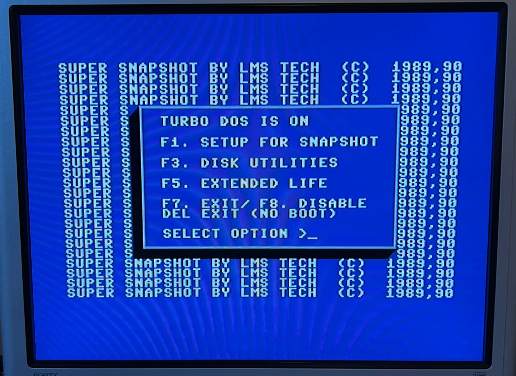
Last basic check before moving to more extensive testing is checking the cartridge. This is done by using the Super Snaphot V. Result is that the test is passed.
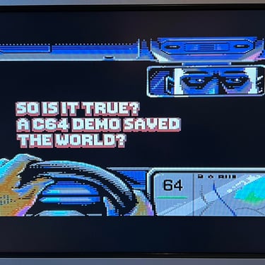
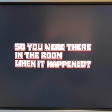
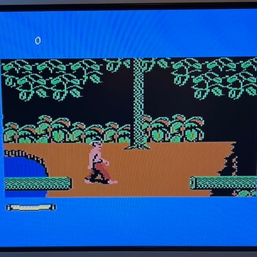
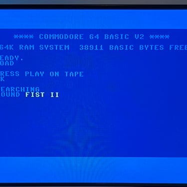
Extended testing
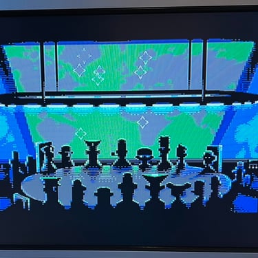
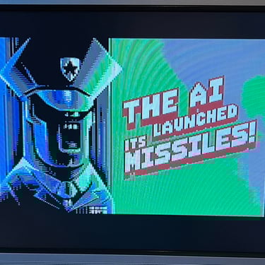
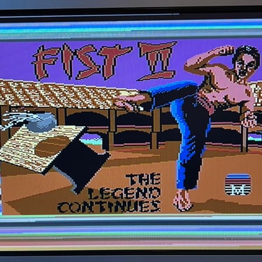
Knowing that the basic functionality of the machine works I continue the testing by using the Commodore 64 for normal operations; playing some games, watching demos, loading from datasette and floppy and using a cartridge. I can not find any issues with this machine. I also pay special attention to the video to make sure that there are no glitches in the graphics - I can´t see any abnormalities. Below is a gallery with pictures from the testing.
Final result
"A picture worth a thousand words"
Below is a collection of the final result from the refurbishment of this C64G. Hope you like it! Click to enlarge!


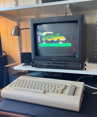
"Are you keeping up with the Commodore? 'Cause the Commodore is keepin up with you!"
Below is a picture of the Commodore 64G back at the customer´s home!
