

SuperKernal
For Commdore 64
[WiFi / 28 pin]
Project scope and plan
A SuperKernal? For the Commodore 64? What´s wrong with the good old Kernal?
There is nothing wrong with the original Commodore 64 Kernal for normal operation. But if you plan to use a real 1541 floppy drive, or add non-custom features to you C64, you should consider changing the original Kernal to a 3rd party ROM. And if you are planning on using speed loaders such as JiffyDOS, DolhinDOS and ProfessionalDOS you have to change the Kernal both in the C64 and the 1541 floppy drive.
The goal of this project is to assemble and configure a 28-pin SuperKernal that will hold several speed loader ROMs. The machine that will have the SuperKernal installed is a C64G [Assy 2250469 / Artwork 242311 (Rev B)].
Milestones
- Assemble 28-pin SuperKernal (with WiFI) module
- Replace BASIC/Kernal IC in C64G with SuperKernal
- Configure SuperKernal with floppy speeder ROMs
- Verify operation by testing
Assembly
The SuperKernal is mostly assembled already, but the assembly needs to be completed before it can be used. The main reason for this is that the SuperKernal can be used to replace both 24 and 28 pin Kernal ROMs. The former is typically used in the old C64 breadbins (aka the "longboards") and the latter is used in newer C64C/G models (aka the "shortboards").
Since this SuperKernal will be used in a C64G [Assy 2250469 / Artwork 242311 (Rev B)] the "28-pin configuration" will be used. The assembly of the module will follow the steps described in the SuperKernal assembly- and user instructions.
What is in the bag?
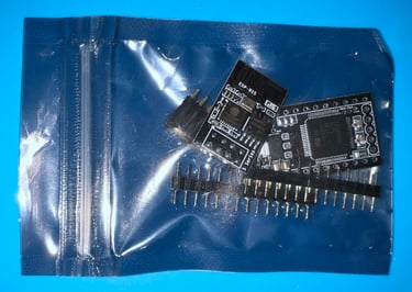
The SuperKernal is received in a closed antistatic bag:
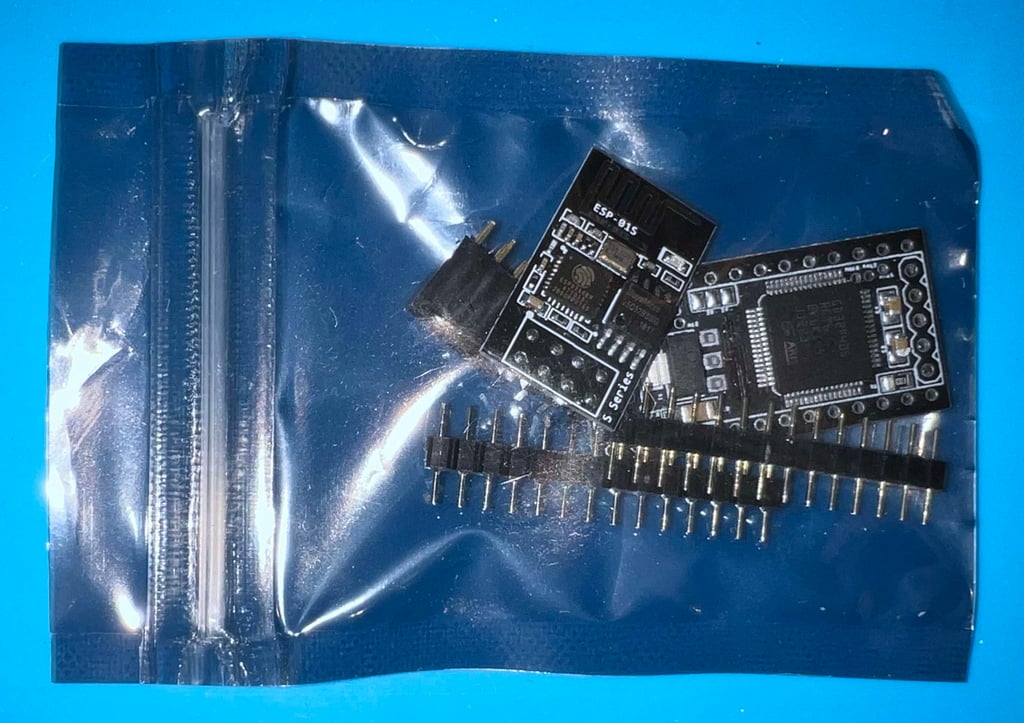
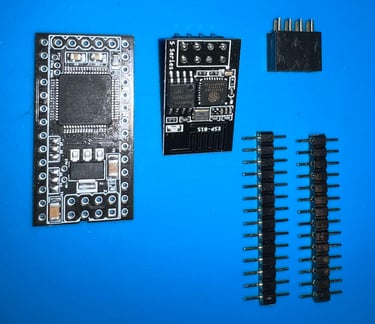
There are five parts in total for the whole SuperKernal assembly:
1 x SuperKernal PCBA
1 x ESP01S WiFi PCBA
1 x WLAN connector
2 x 14 pin header
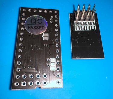
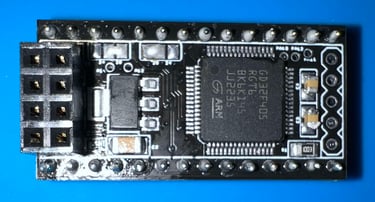
Pictures below of the parts (front- and back view).


Soldering the parts
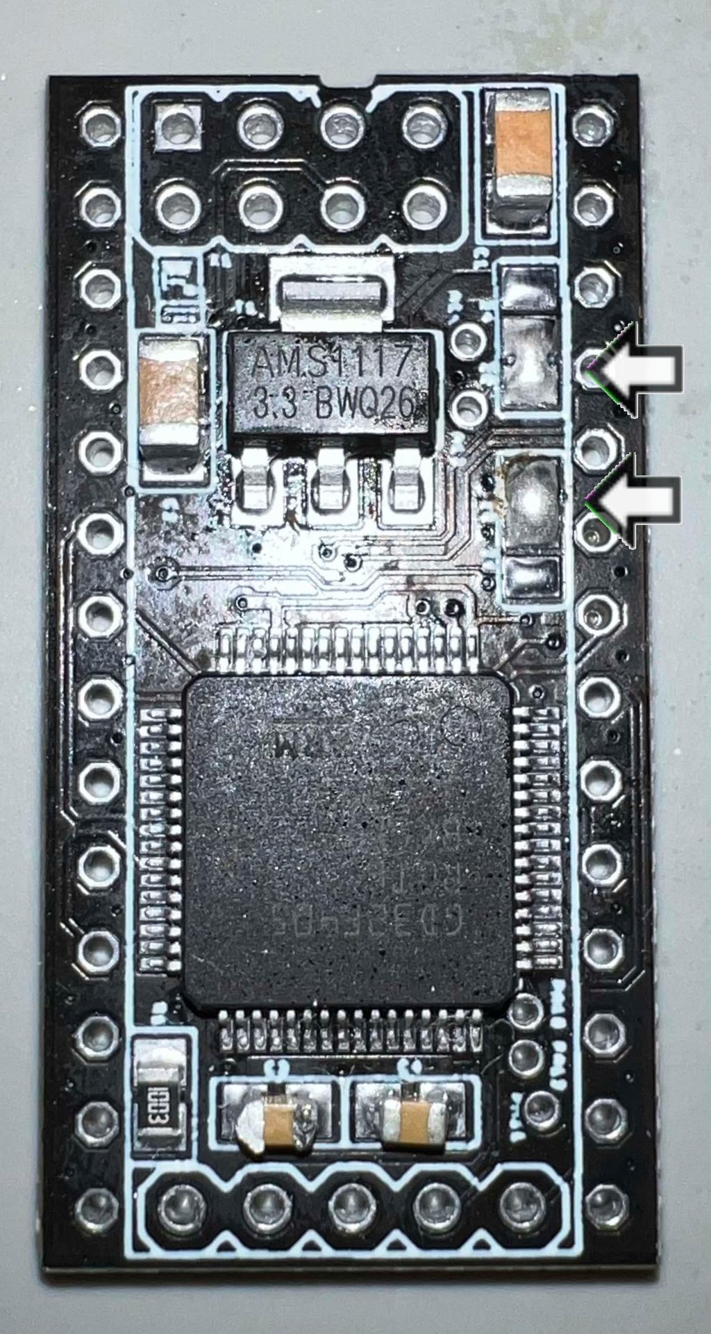
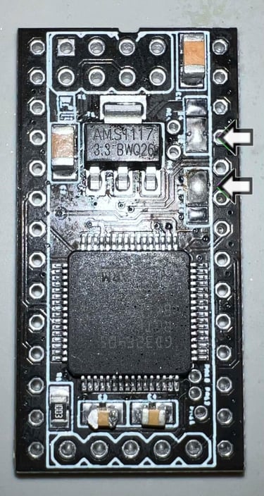
The first thing to solder is to bridge the two jumpers. These jumpers are used to set either the 24- or 28 pin configuration. Following the instructions the bottom two points of the first jumper are bridged, and the top two points are bridged on the second jumper. See picture below.
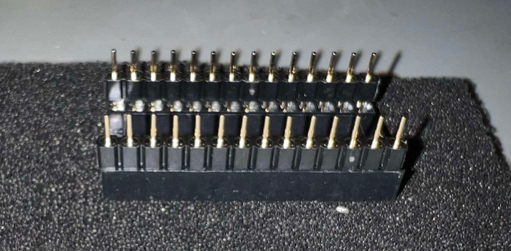
Next the 2 x 14 pin headers are soldered to the PCB. Using a small trick (from the instructions) the pin headers are first placed in an empty socket and then the pin headers are soldered to the PCB. This would help align the pins to the socket.

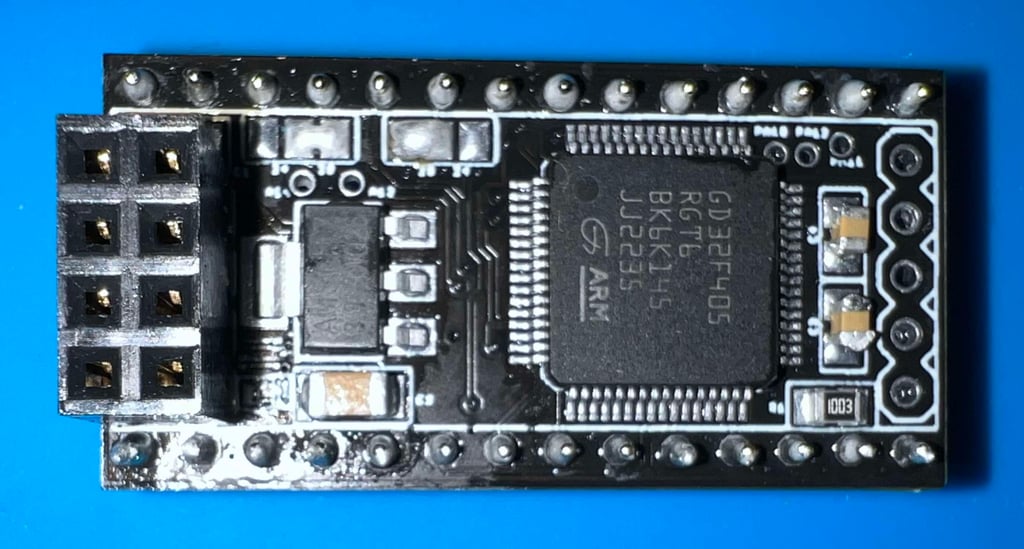
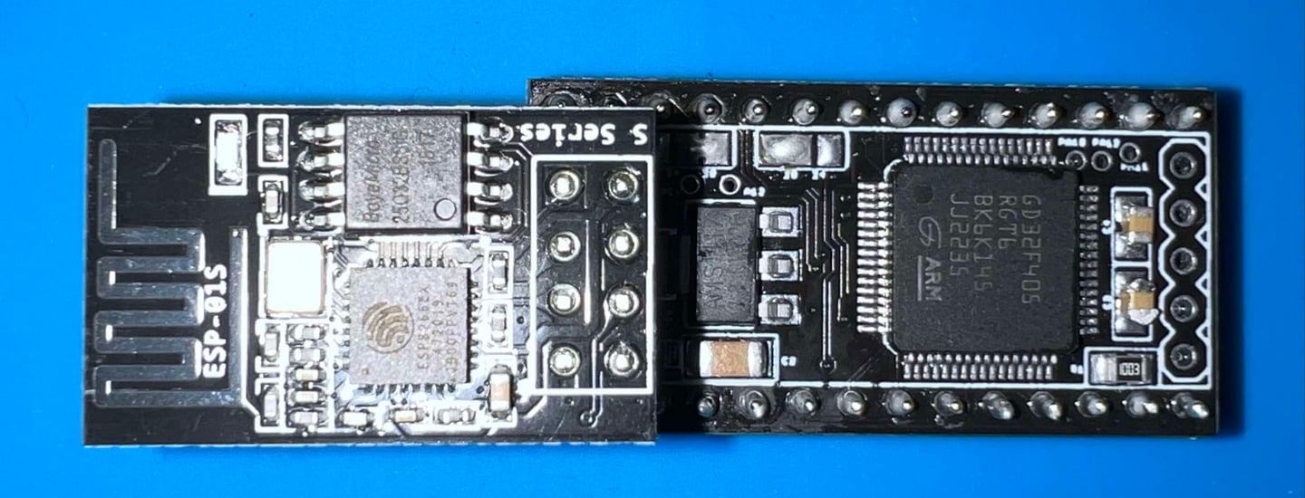
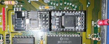
The WLAN connector is also soldered to the PCB. Below is are pictures of the PCB with everything soldered and with the WIFI module attached.

Replacing the Kernal/BASIC ROM
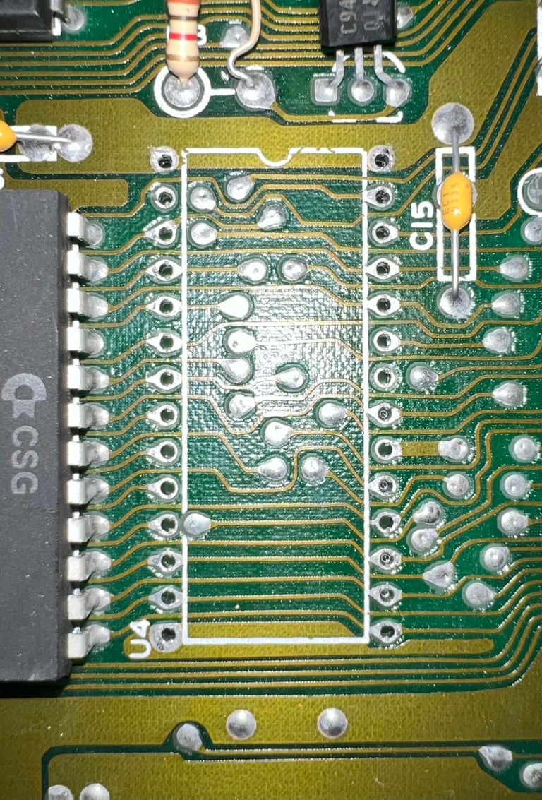
As previously mentioned this project will install the SuperKernal in a C64G [Assy 2250469 / Artwork 242311 (Rev B)]. This 28-pin ROM is located in position U4.
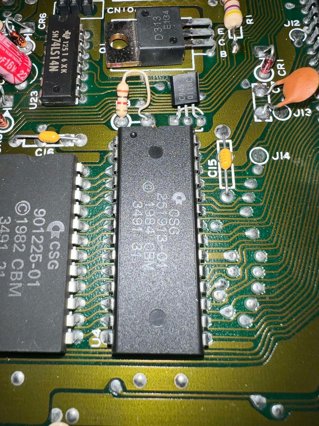
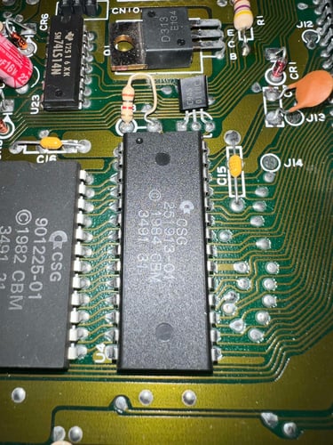
The IC is desoldered without any damage to traces or pads. See pictures below.


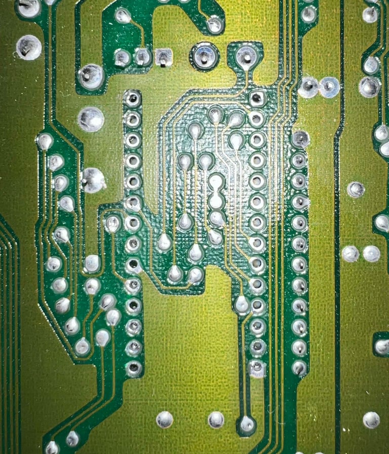
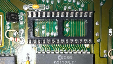
After desoldering a dual wipe 28-pin socket is soldered back in.

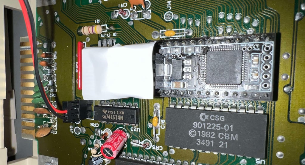
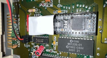
The SuperKernal module (with the WiFi module) is inserted in the socket.
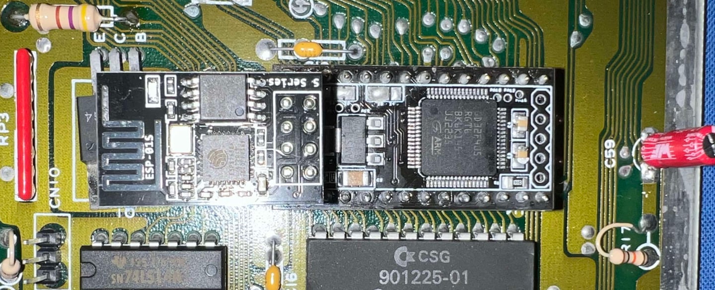
I could be wrong, but I think that the WiFi-module might touch the back of the keyboard (?). Since there are quite a few small metal screws on the back of the keyboard I place a piece of insulation tape covering the WiFi module.
Configuring the SuperKernal -
for floppy speeders
The main purpose for installing the SuperKernal is to have multiple ROMs for multiple floppy speed loaders (e.g. DolphinDOS, Professional DOS, Prologic DOS etc.) in the C64 to be used in adjunction to a 1541-II equipped with MeGALoDOS transferring data on the user port in contrast to serial speeders (more about this in another article).
A detailed description of how to configure the SuperKernal can be found in the SuperKernal assembly- and user instructions.
Basic configuration
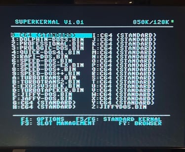
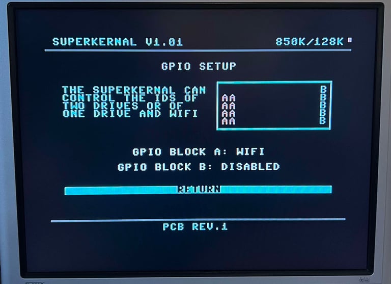
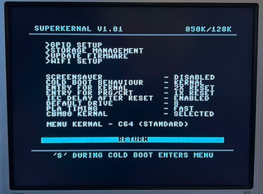
At first power-on the screen shown below is displayed. As can be seen it is equipped with firmware version 1.01.

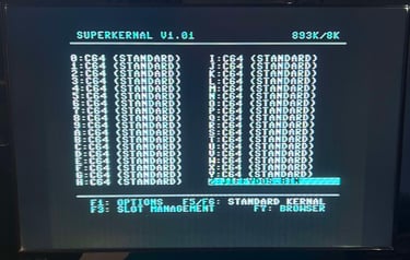
As can be seen from the picture above there are 36 available slots for different Kernals which there are currently only two "really" used: the C64 original Kernal and JiffyDOS (serial interface floppy speed loader).
Since the plan is to use MeGALoDOS with both USER- and SERIAL port floppy speed loaders a range of ROMs are installed to the SuperKernal. This operation is very straightforward. A D64 disk image is prepared with a range of different ROMS (both for USER- and SERIAL port floppy speeders), the disk is mounted to the C64G using an Ultimate II+ cartridge (drive 8) and 15 ROMs are uploaded to the SuperKernal one-by-one.
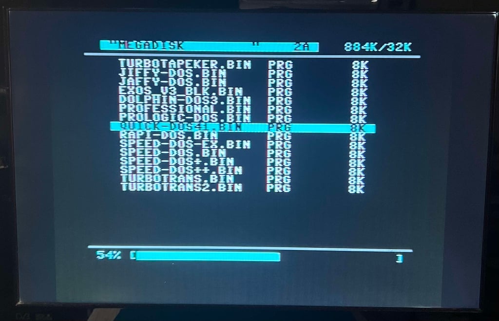
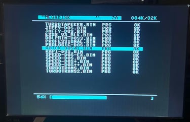
Slot 0-F are used for this purpose (note that slot 0 is reserved for the original C64 Kernal).

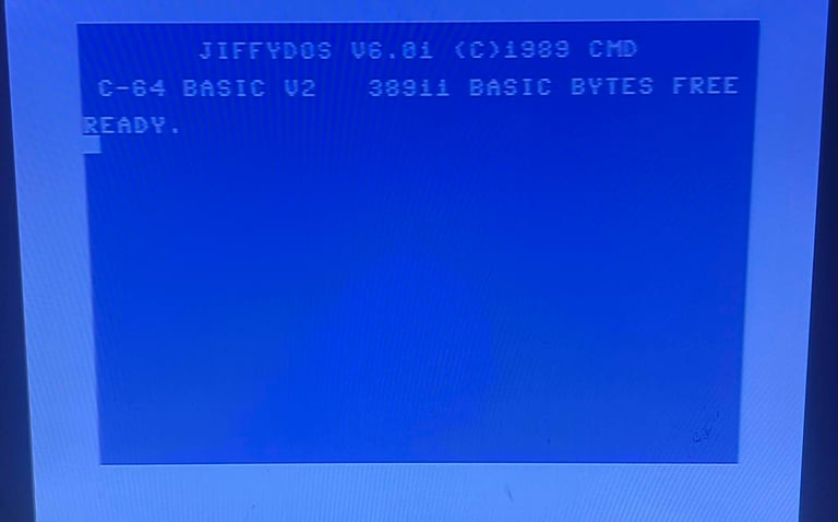
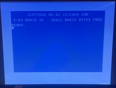
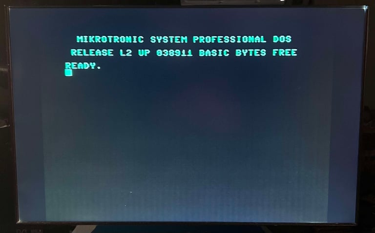
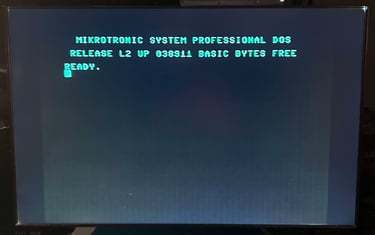
A quick test with both a USER PORT and SERIAL PORT ROM seems to work ok (Professional DOS and JiffyDOS respectively).
Advanced configuration
There are two other areas which are configured:
WiFi settings
PLA Timing
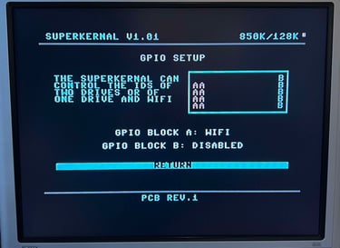
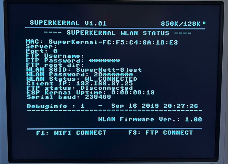
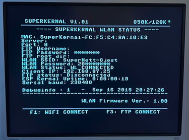
To configure the WiFi settings the module needs to be enabled first. This is done by setting the GPIO block A to "WiFi". With this enabled the WiFi module is configured by registering the SSID and password for the local WLAN. See pictures below. Please note that I do not have access to a FTP server at the moment, but the WiFI connection seems to be working fine.
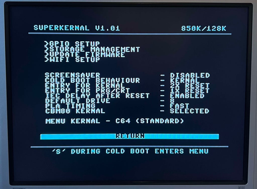
It is also possible to adjust a parameter named PLA TIMING. From the user manual the following is said about this parameter:
"PLA TIMING: The SuperKernal automatically tries to achieve the best compatibility for all boards. Unfortunately, due to component tolerances of these over 30 years old computers, there is no 100% guarantee that the SuperKernal will run perfectly on every board. Therefore, you can try to adjust the timing manually for some boards. Old C64 computers of the first series run almost all on SLOW, SLOW and FAST and new computers like the C64G(C64II) almost exclusively on FAST. If you play around with this menu item you might theoretically end up with a crash when starting Kernals or programs. In an emergency you can always return to the SuperKernal menu with several resets + holding the "S" key."
Since this is a C64G, with the short-board, the PLA timing is set to "FAST".
Testing
To test if the SuperKernal works as expected in the C64G the following steps are performed:
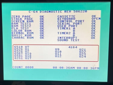
Basic testing with Dead Test- and Diagnostic cartridge (wtih harness)
Basic testing
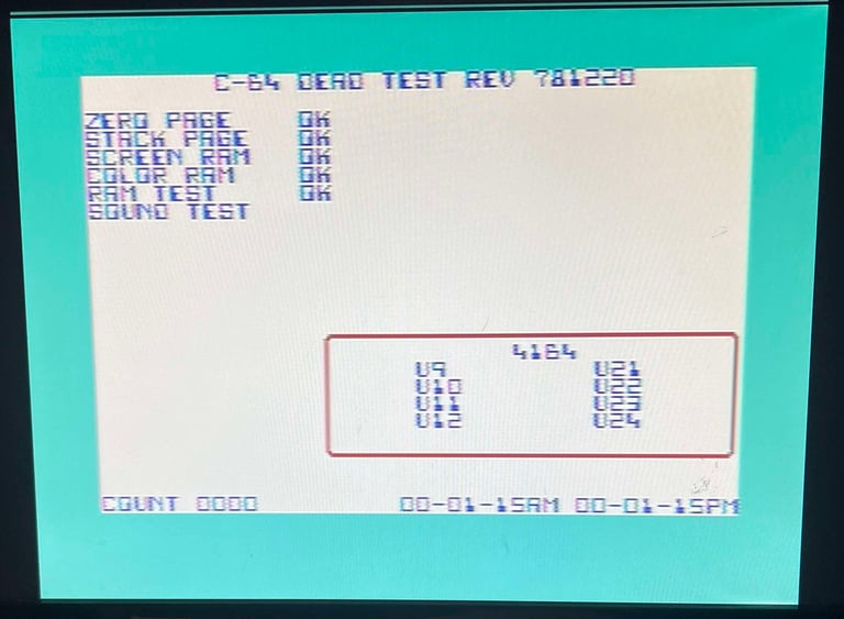
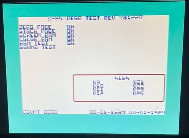
WARNING: Even if the screen below shows that the Dead Test cartridge works fine I did experience at first that it did not (some parts of the characters were missing and crashed). Unfortunately, I did not manage to reproduce the problem and therefore can not show a picture of it. But even if the problem is not present at the moment I do not assume that it is completely gone.
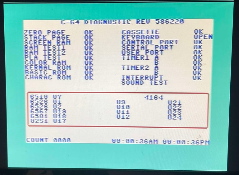
Below are pictures from the testing with the Dead Test- and Diagnostics cartridge. No faults are detected in these.
Banner picture credits: Frank