
Competition Pro
Starting point
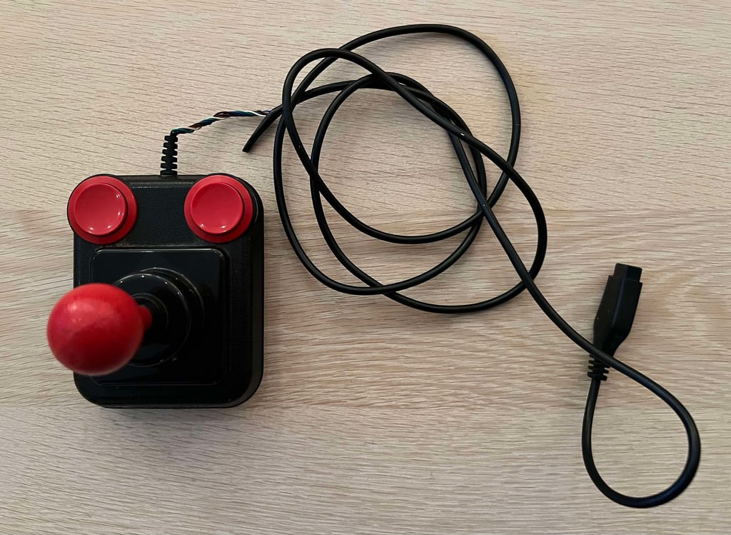
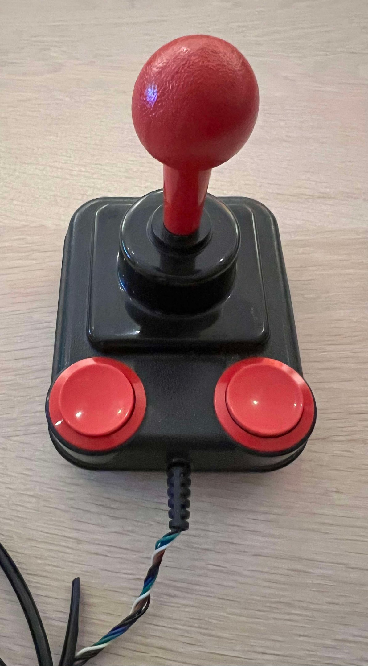
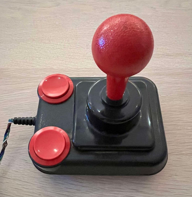
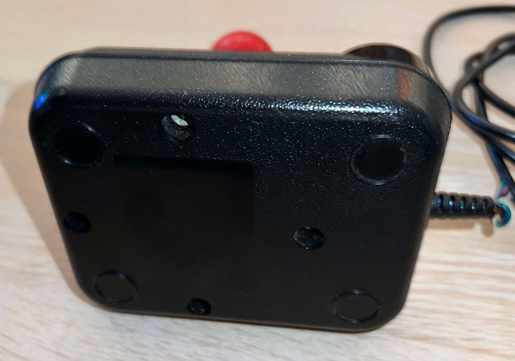
The state of this Competition Pro is not in a too bad. But there are some areas which needs to be addressed during refurbish:
It is literally full of grease. The pictures does not do it justice - it is way worse than it looks. A thin "film layer" of some kind of grease.
Squeaky! When moving the joystick shaft in different directions some very annoying "SQUEEEEEK!" noises can be heard
The strain relief appear to be ok... but some previous owner has managed to pull out the wires from the casing! How?!
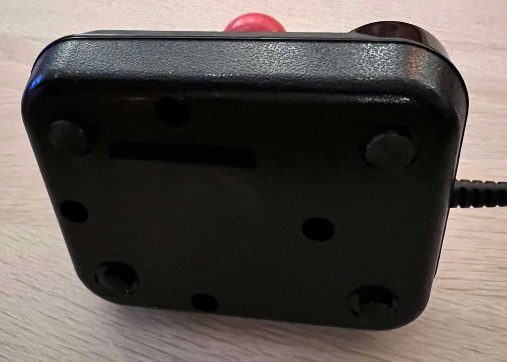
All of the four rubber feet are gone. I do belive that this joystick were equipped with rubber feet originally.
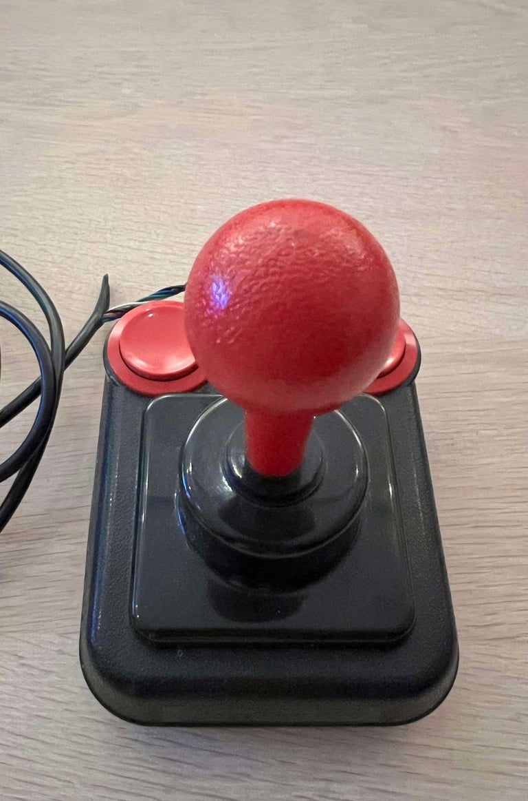
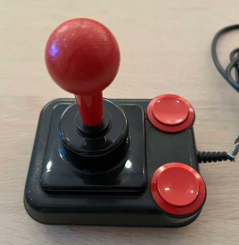
As far as I know there are two main revisions of the Competition Pro. One with the smooth ball top and FIRE button microswitches. And one with a knotted ball top and use leaf switches for the FIRE button. This joystick is of the latter version. Both version are from my experience just as good - both very high quality joysticks.
Below are some pictures of the Competition Pro joystick before refurbish.






Refurbishment plan
To refurbish this joystick the plan is to do this trough the following steps:
- Clean, and remove stains from, chassis and all parts (and repair if required)
- Lubricate moving parts
- Clean and check the microswitches (and repair if required)
- Check connectivity (and repair if required)
- Verify joystick operation by testing
Disassembly
Starting the disassembly
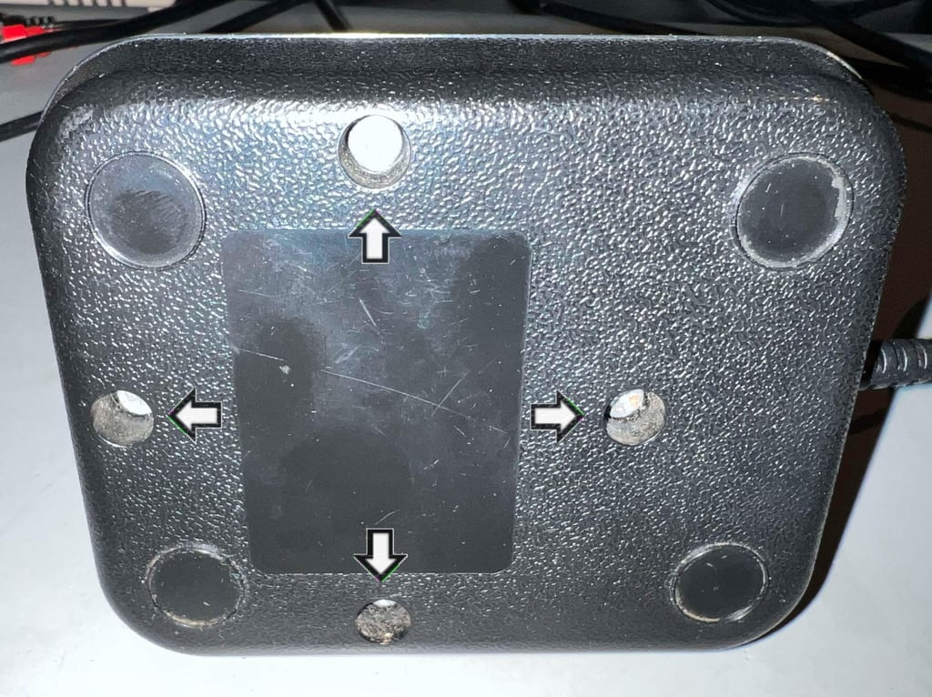
Disassembling the Competition Pro starts with removing the four screws at the bottom cover (Philips 3.5 x 16 mm).

With the screws out of the way the top cover is lifted off. And, holy moly, there is quite a lot of dust and grease inside! How did that happen?!
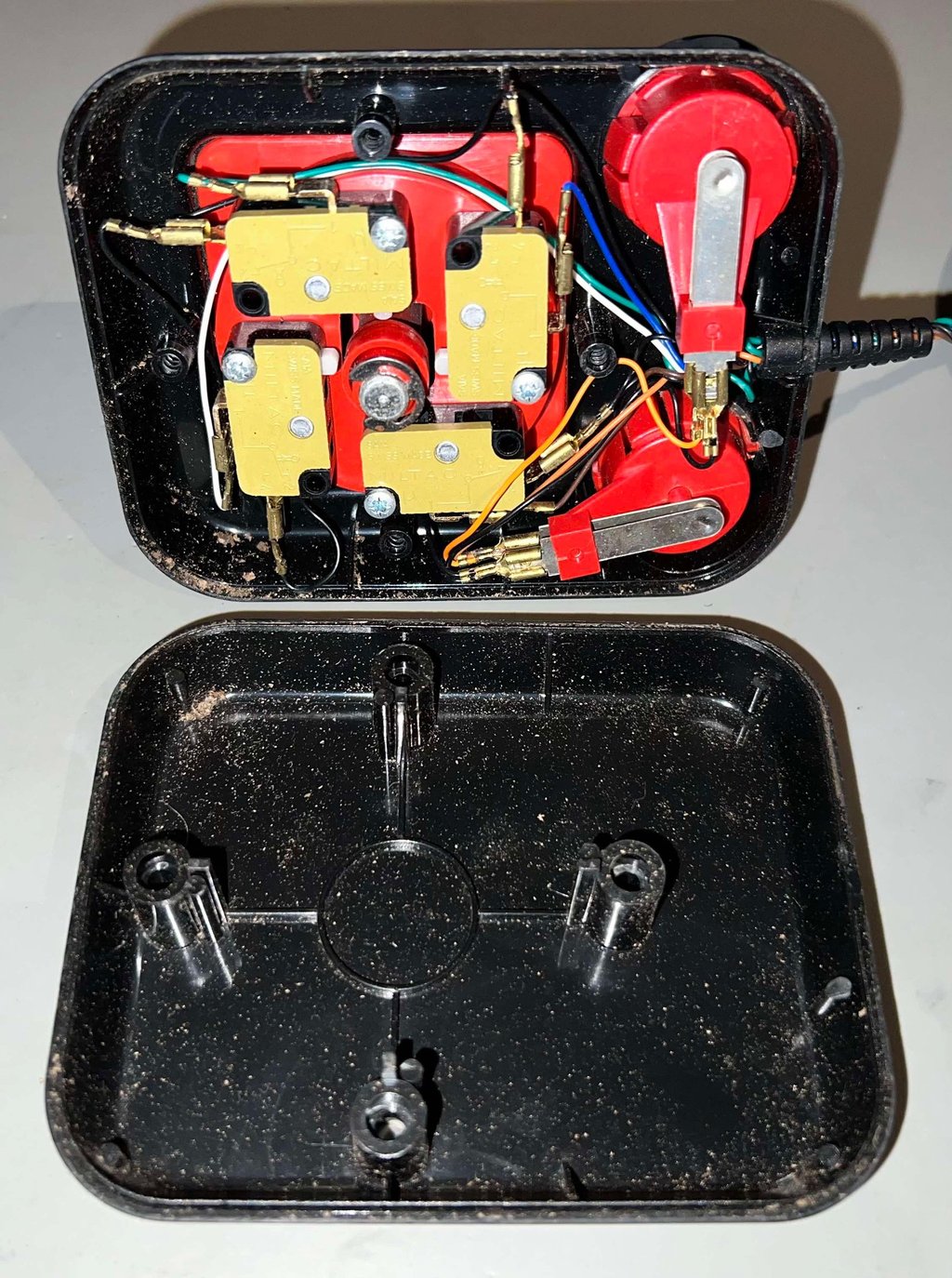

Removing the plastic bracket (with the microswitches) from the top cover require a bit of careful "wiggling" to avoid any damage to wires or parts.
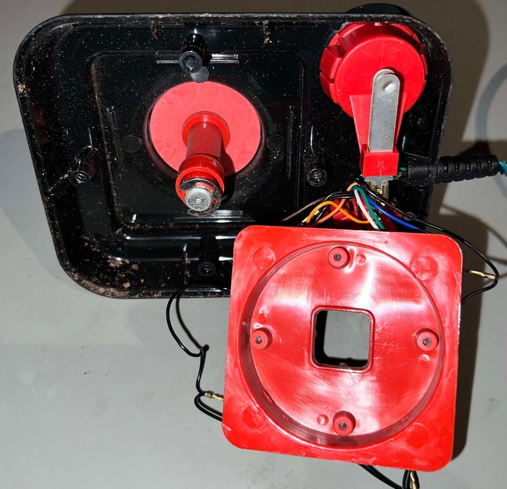

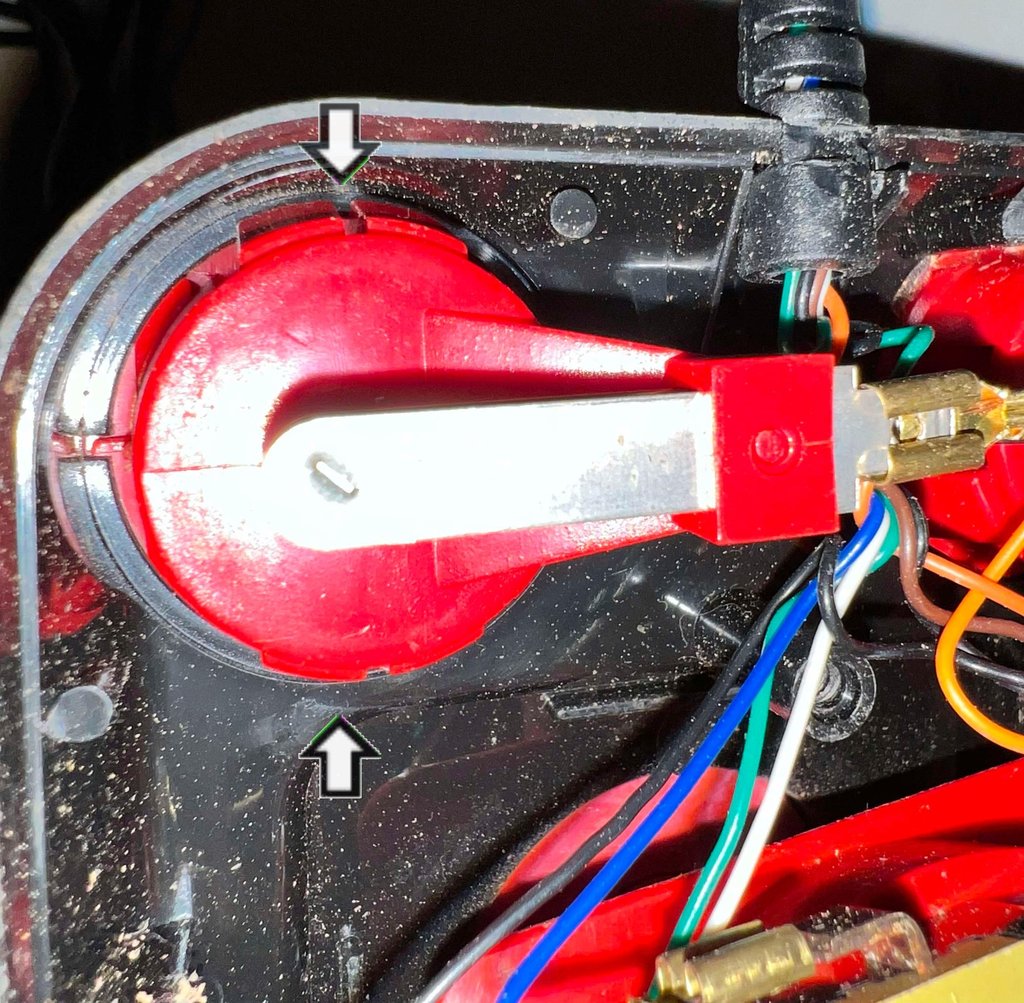
Next action is to remove the FIRE buttons from the top cover. By carefully pushing the plastic tabs on both side, and at the same time push the FIRE button outwards, the plastic module is released. Please note that 30+ year old plastic can be brittle, so be careful.

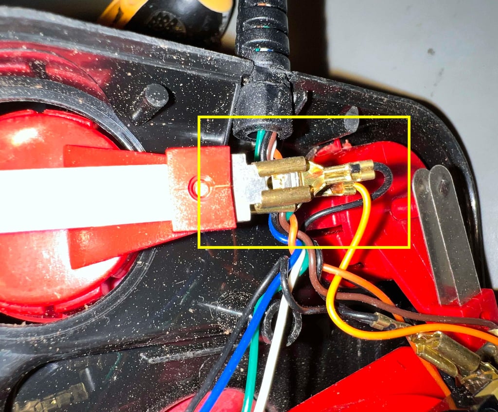
In contrast to other versions of the Competition Pro, the wires are connected to the leaf- and microswitches using cable shoes - instead of being soldered directly to the connectors. All of the cable shoes are a bit loose, but they are "stuck" to the connector using a small barb (as in a fishing hook) preventing it from falling off. But with a small flat screwdriver all of the cable shoes are removed from the switches.

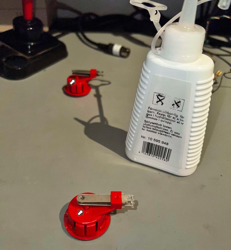
Disassembling the FIRE button modules
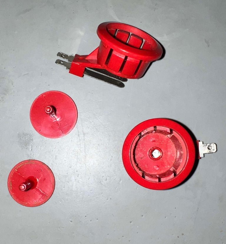
The FIRE button module consists of two parts which are pressed together at production. To separate these a small trick is used: sewing machine oil. By applying a tiny drop of oil at the barb tip, the tip can be pushed inwards to the bottom part of the module. I use a large flat screwdriver to apply enough force to the tip.


Disassembling the joystick shaft
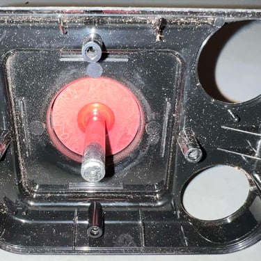
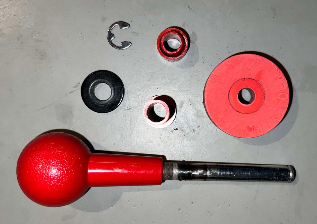
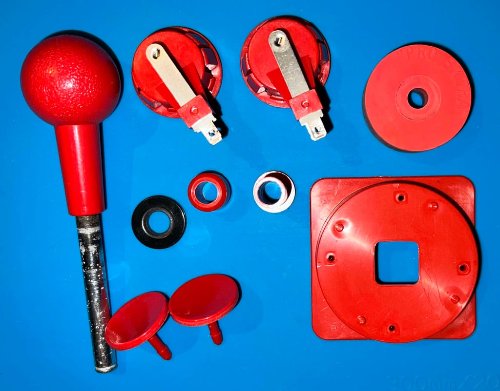
First thing is to remove the E-clip at the bottom of the joystick shaft. A small thin flat screwdriver is an appropriate tool for this. With the E-clip out of the way the parts can be removed one at the time. NOTE: to remove the large rubber ring a stump plastic rod can be used. By pushing the rubber ringg from the top of the cover towards the bottom the rubber ring will pop out. If you try to remove the rubber block from the bottom side you risk damage both to the rubber and the plastic casing. Below is a small gallery from the process. Click to enlarge.
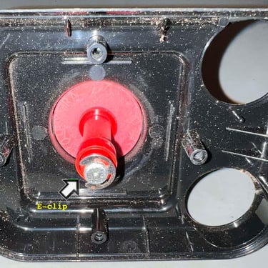
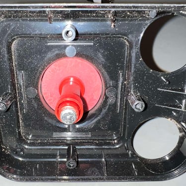
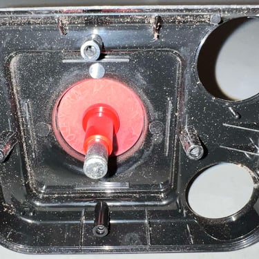
In the picture below all parts making up the joystick shaft is shown.

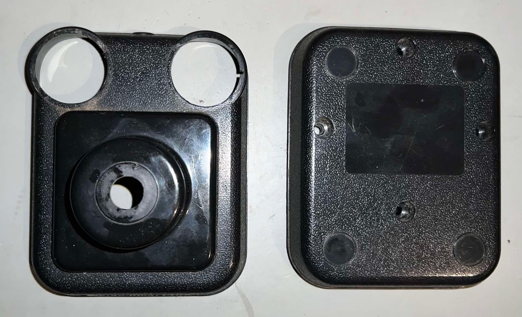
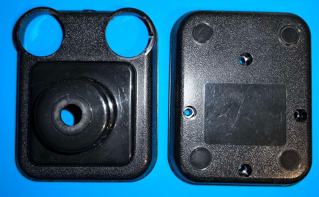
Now the joystick is disassembled and ready for refurbish. As can be seen from the picture below the top- and bottom cover are in quite good condition, except from some dirt and grease (and some sign of use).

Exterior casing and plastic parts
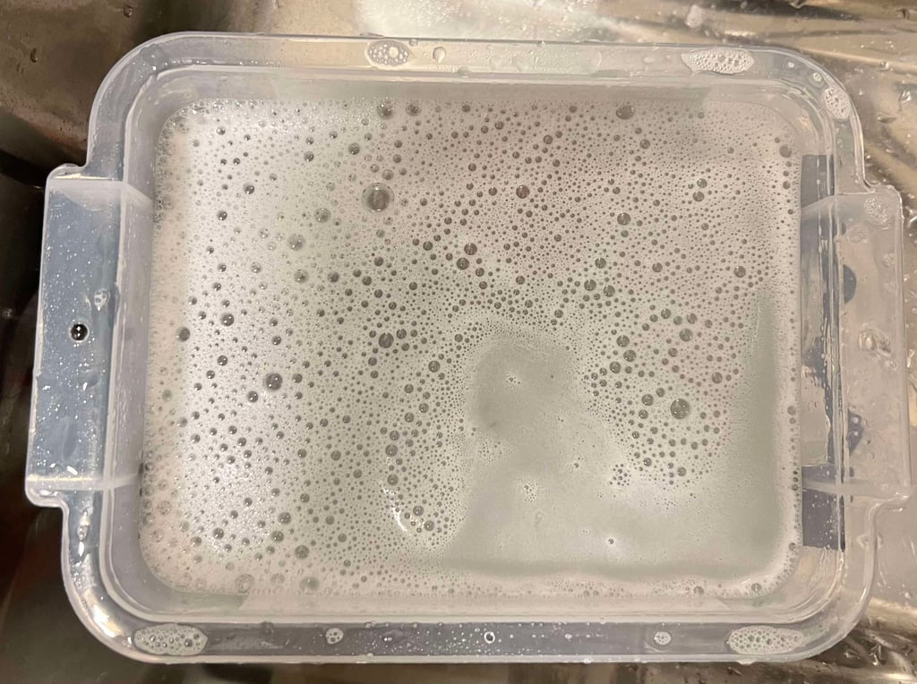
All of the disassembled plastic parts are placed in a box filled with mild soap water and some glass cleaning spray for about 24 hours. This will dissolve most of the grease from the parts. Note that the metal parts are not cleaned this way, they are just cleaned with a clean paper towel (the bottom casing of the FIRE button is considered a "plastic part" and is placed in the soap bath).
As previously mentioned there are two (as far as I know) versions of the Competition Pro. Another difference between the versions is the use of a spring and/or rubber ring. This joystick which is under refurbish use the large rubber ring to center the joystick shaft, but the other version use a large spring instead (see this Competition Pro).

The parts look very good after cleaning and drying. Good as new?


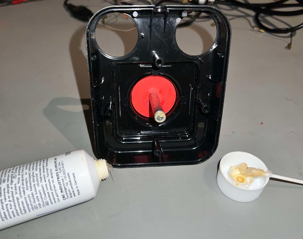
I find it to be good practice to lubricate some of the moving parts with multi purpose grease. This is not strictly required, but the rubber ring (and the plastic parts) are quite dry after 30+ years. So a small amount of grease will reduce friction and squeaky noises.

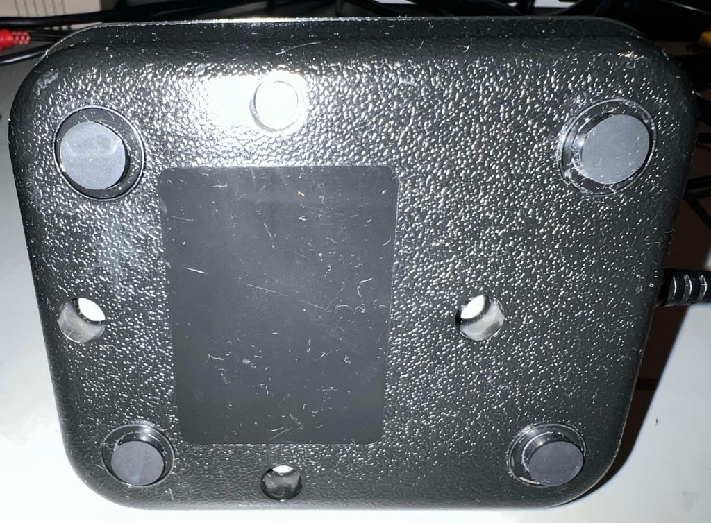
All of the rubber feet are gone. So some new are added! These rubber feet have a bit different dimension (3 x 10 mm), but they will do just fine I think.

Electronics and microswitches
The four microswitches are used for the RIGHT/LEFT/UP/DOWN direction and they appear to be in good condition. Both the sound of "click" and the felt response from the switches all appear to be very good. On the other hand, the cable is a sad sight.
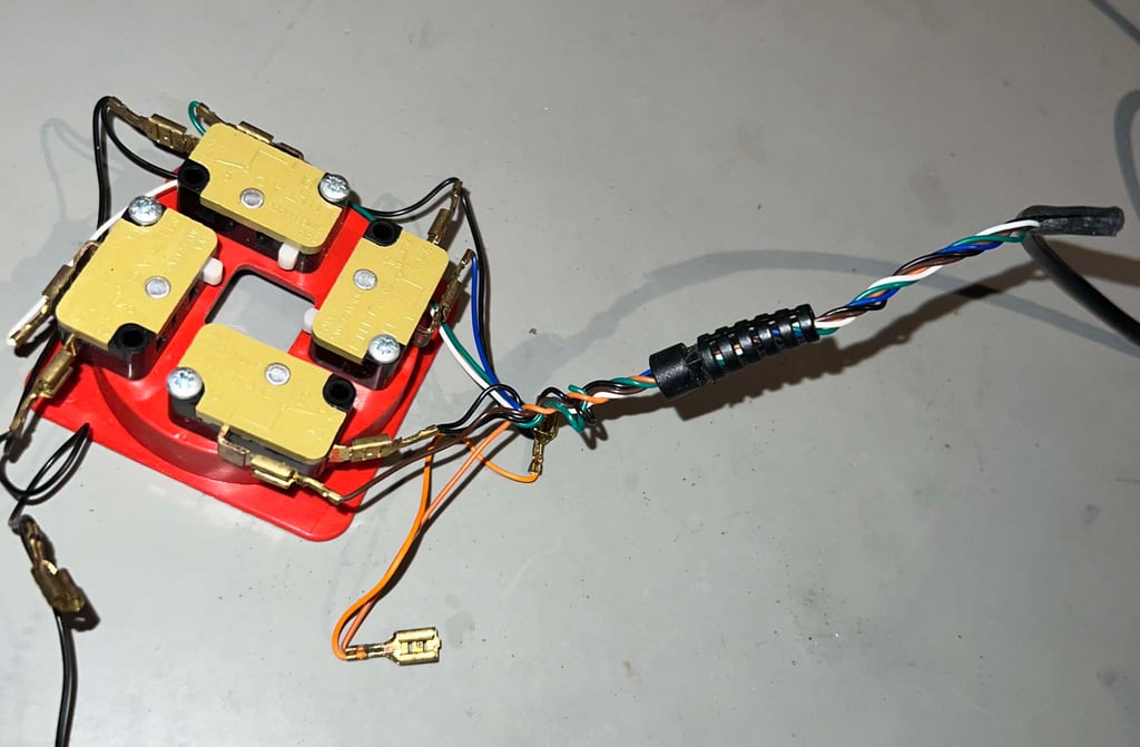

But the cable is a bit of a mystery... why does it look like this? What I see from the visual inspection:
All of the inner wires appear to be in fine condition. No signs of broken insulation or repair attempt.
The cable strain relief is undamaged. A previous owner has somehow dragged the wires out of the strain relief.
The length of the wires appear to be original. No signs of rework on the cable shoes.
There is a small rip on the outer insulation of the cable. How come?
When the Competition Pro is assembled at factory the wires are also twisted around one of the stand-offs adding addition cable strain relief. So why has this happened? This is a bit of a mystery.
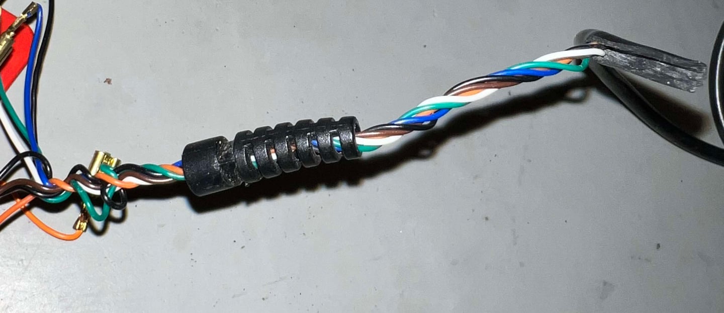

Repairing the cable
The cable is attempted repair doing the following steps:
The ripped part of the outer insulation is cut with a pair of fine cutters
About 2 cm of the outer insulation is covered with some fine sewing machine oil as lubrication
With some wiggling and careful pulling the cable is put back in the strain relief
A small cable tie is attached to the large end of the strain relief to secure it. This will not be visual as this part of the strain relief is inside the joystick.


Checking and cleaning the microswitches
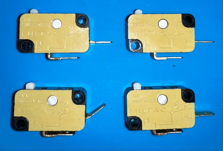
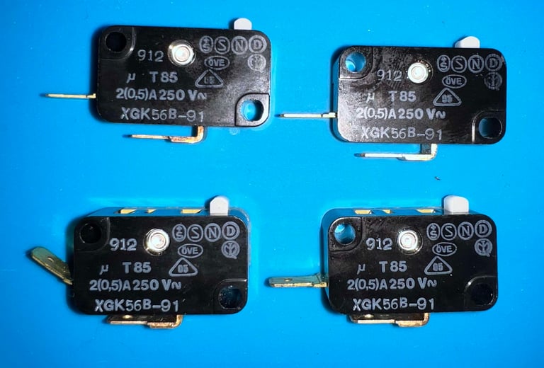
All of the four microswitches are of the brand "MILTAC - SAIA" and are made in Switzerland. This also give some hint on when these microswitches (and hence the joystick) were made. SAIA was an independent company until 1989 when it was merged with Burgess Productions using the name "SAIA Burgess" from then. So I think we can assume that this joystick was made sometime before 1989. The microswitches are mounted to the plastic bracket with four pozidrive 3 x 16 mm screws.
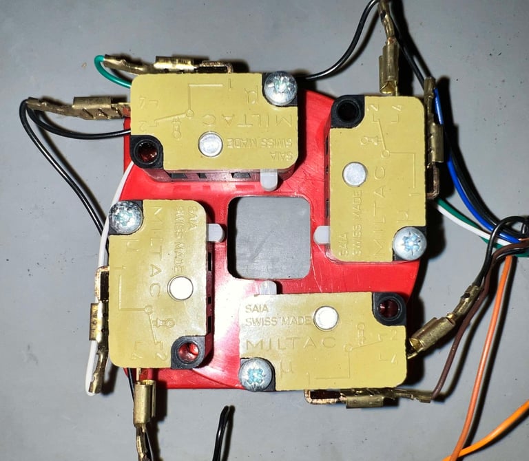

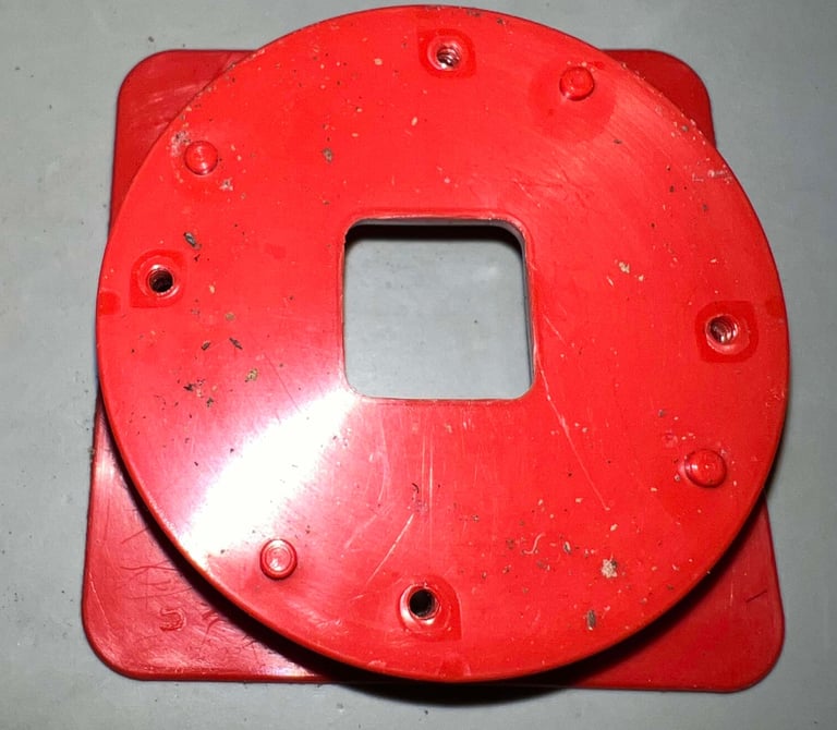

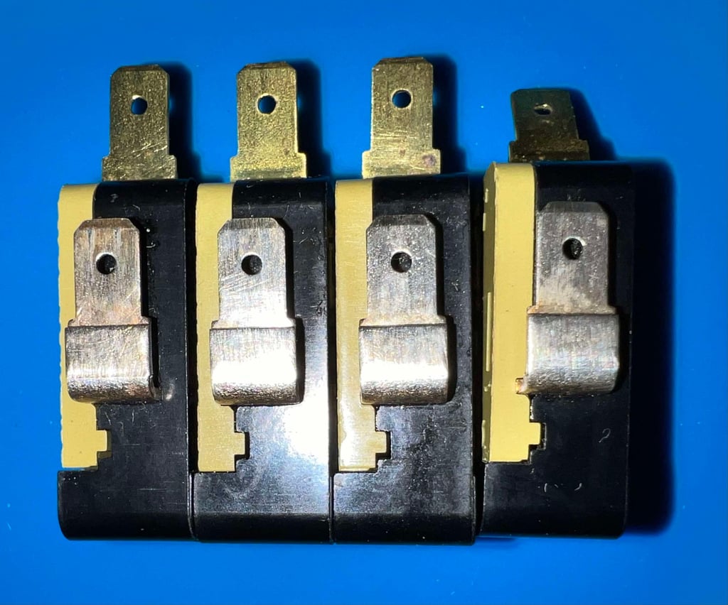
The four microswitches are cleaned properly with isopropanol. And in addition the metal connectors are also deoxized with a steel brush. Note that one of the metal connectors appear being "bent" compared to the other switches, but this is how they were originally (see also picture above - microswitch bottom right).



Checking the wire connectivity
It is good practice to check that all the wires going from the connector (C64 side) to the inside of the joystick for continuity. To do this I use a normal multimeter in diode-mode (aka beep-mode). But when doing this I get a bit surprised. Several of the wires do show a connection - but with a higher resistance than I would expect. Normally, the resistance in the wires is about < 10 Ohms, but here the resistance... seems to vary? What is going on?
At first I get the impression that the wires are in fact bad. But they are not. They work perfectly when I test the microswitches on a Commodore 64. I am not 100 % sure, but I think that the reason for the weird reading is the multimeter probes not making good contact to the cable shoes.
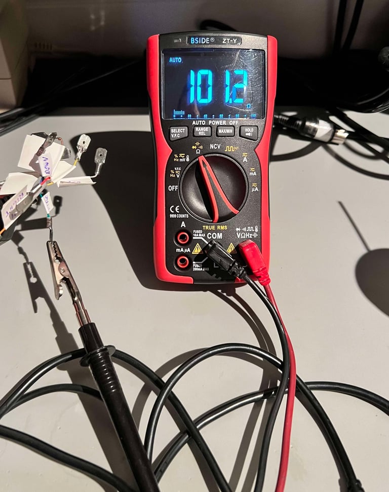

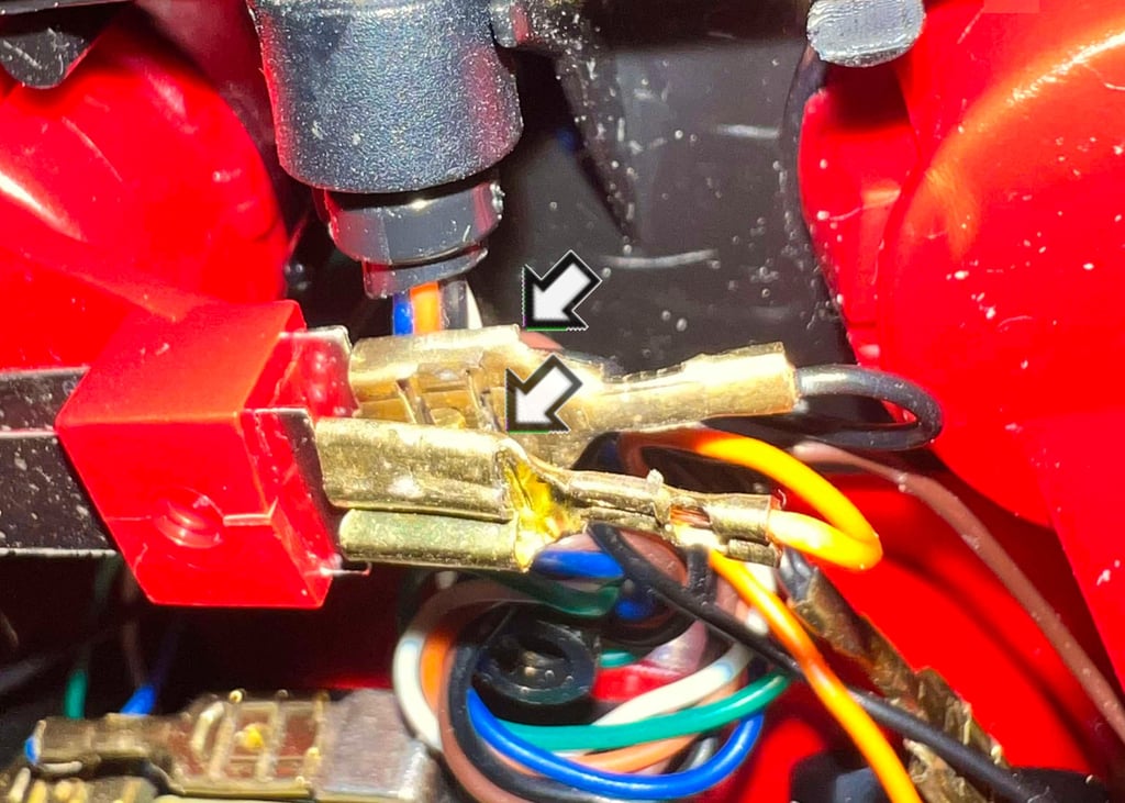
As mentioned previously the cable shoes feels a bit loose to the grip. In combination with the "weird readings" I decide to squeeze the cable shoes to metal connectors using a pair of pliers. This will make the cable shoes sit tight and should also provide additional contact area.

Refurbishing the leaf switches
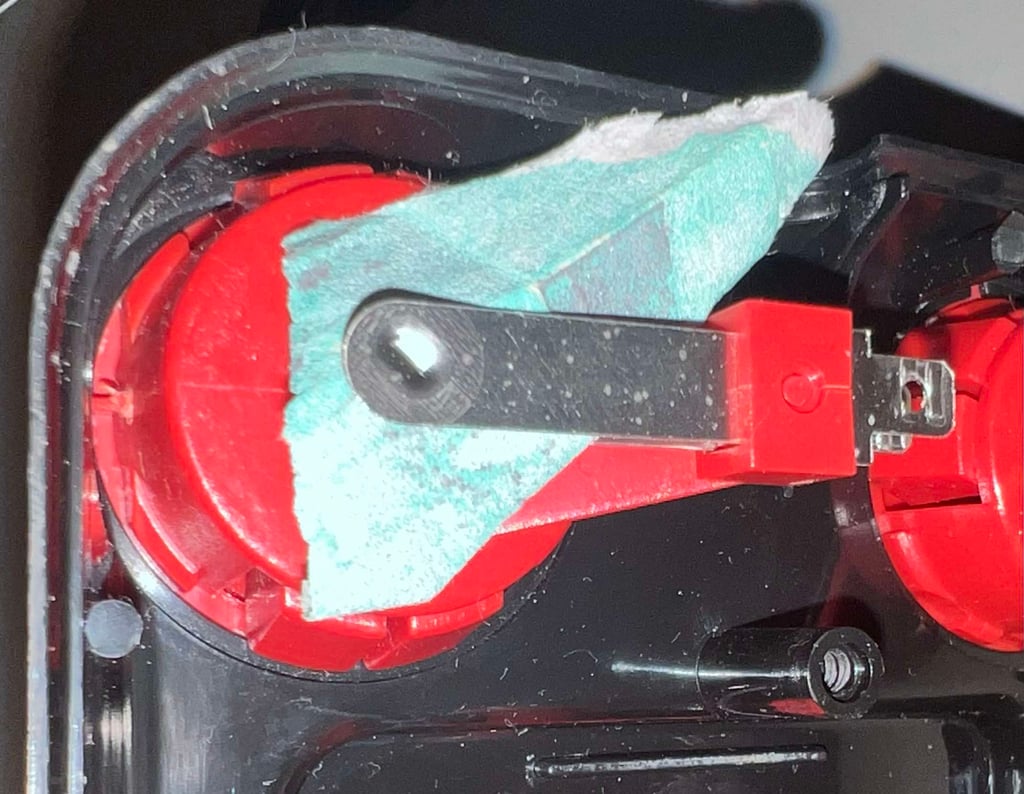
The leaf switch is a simple, but yet effective, design. By pressing to metal sheets together the switch is closed. But if the metal sheets are not free from oxidation you tun the risk that the metal sheets will not make (proper) contact. Removing the oxidation between the leafs can´t be done (without damage) using normal tools such as a brass brush, but a small piece of sanding paper does the trick! Remember to clean the metal sheets with isopropanol, or contact cleaner, to remove all residuals.

Testing
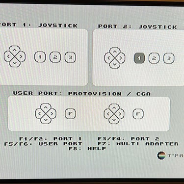
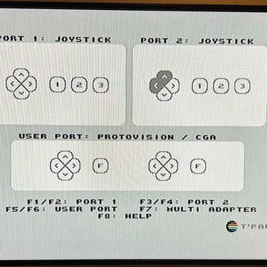
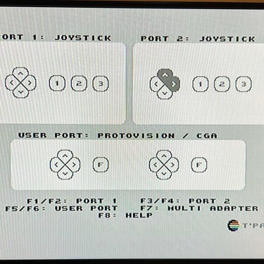
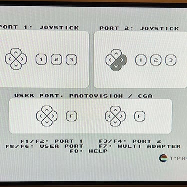
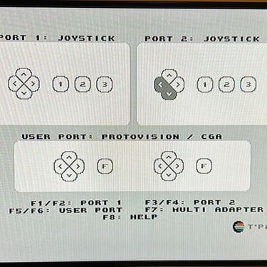
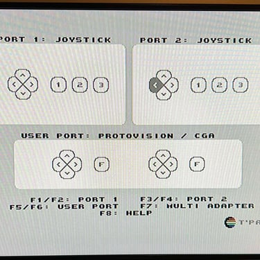
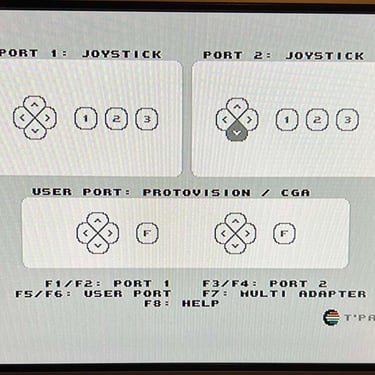
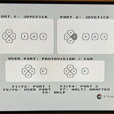
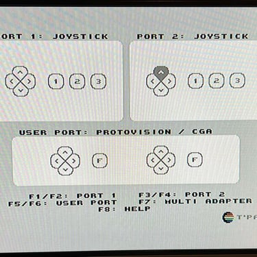
To verify that the joystick work as it should I check it with the Joyride software. Result is that all directions and fire buttons works fine works as expected. All tests pass.
Final result
"A picture worth a thousand words"
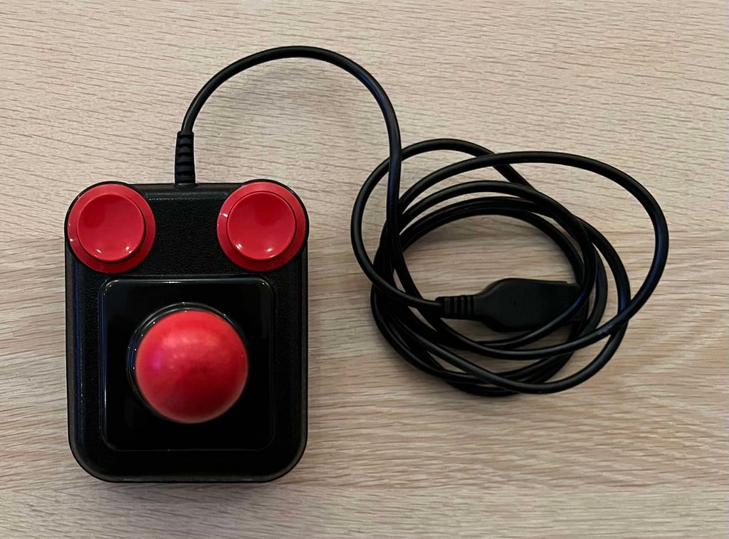
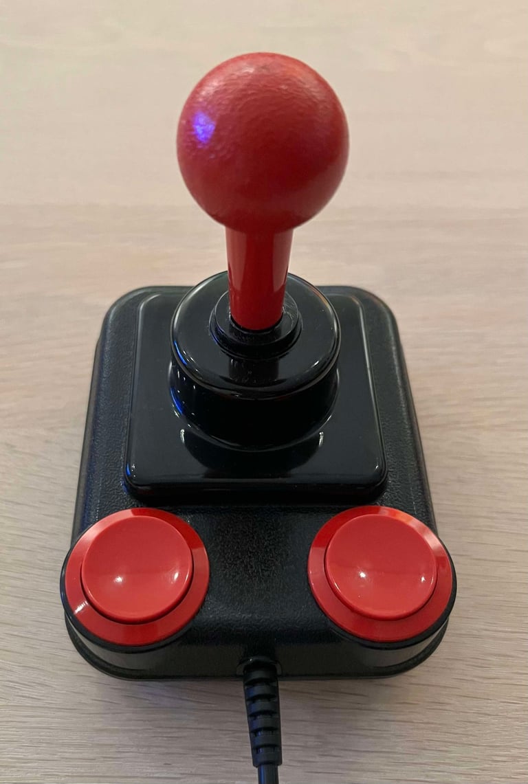
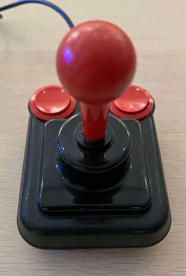
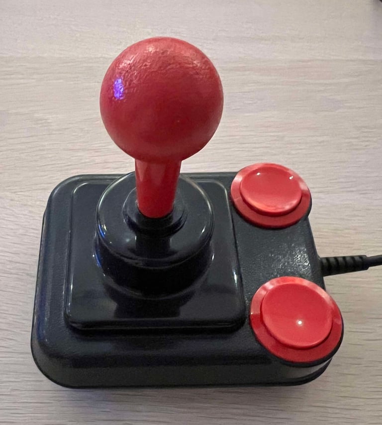
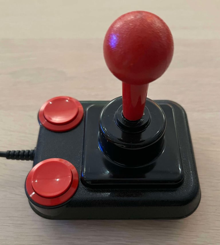
Below is a collection of the final result from the refurbishment of this Competition Pro joystick. Hope you like it! Click to enlarge!






Banner picture credits: Kshade
