

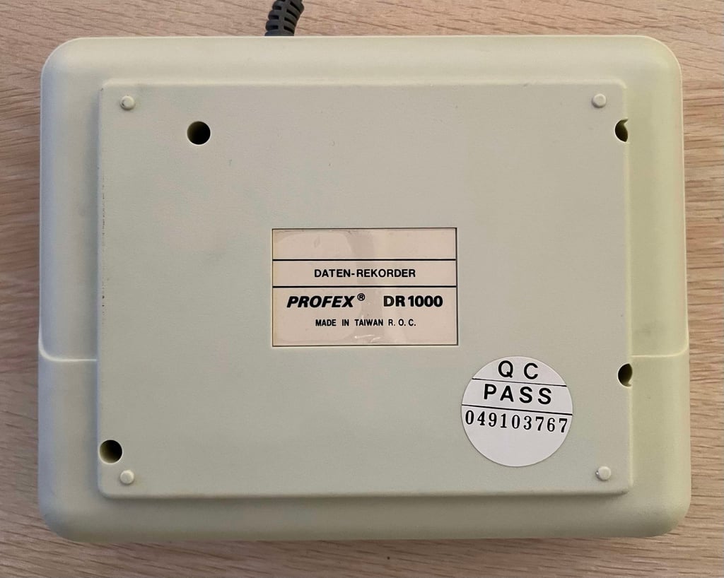
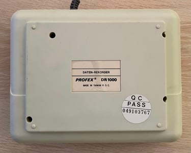
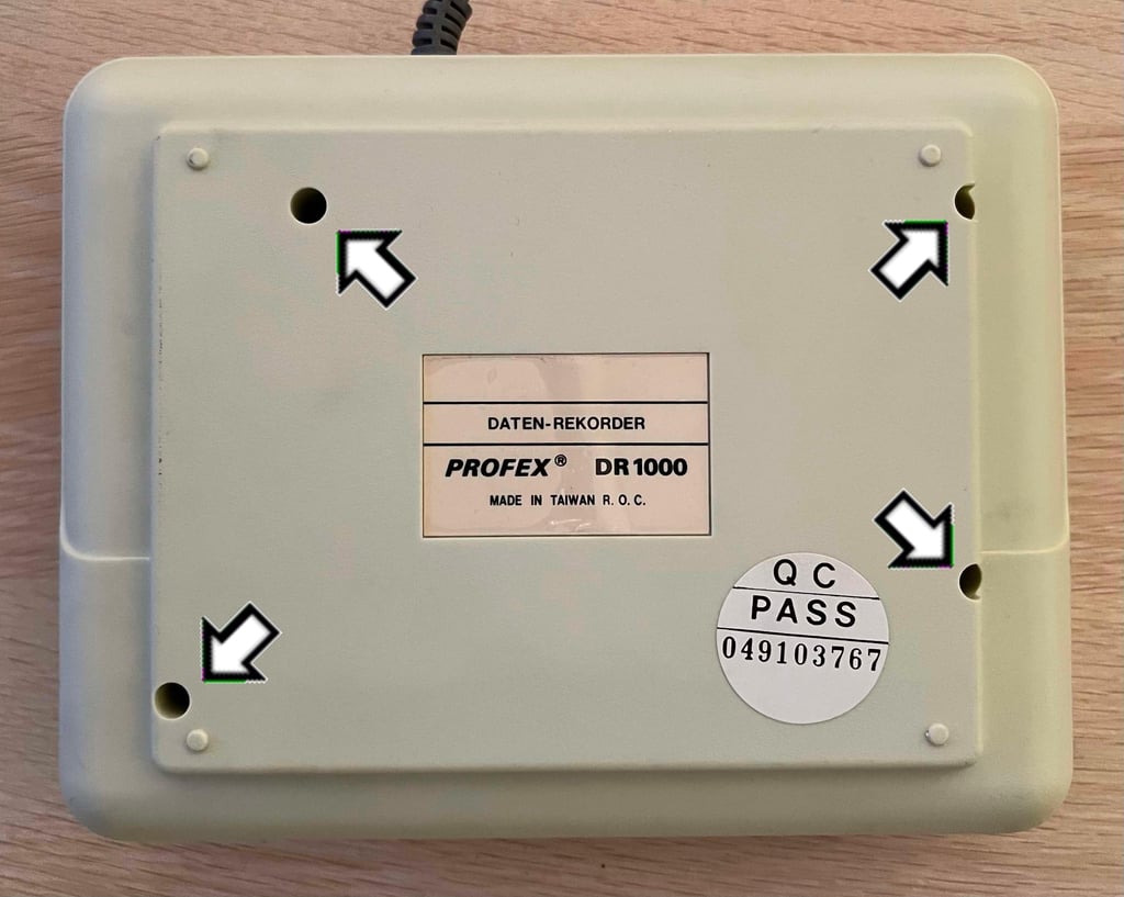
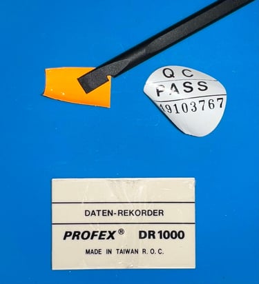
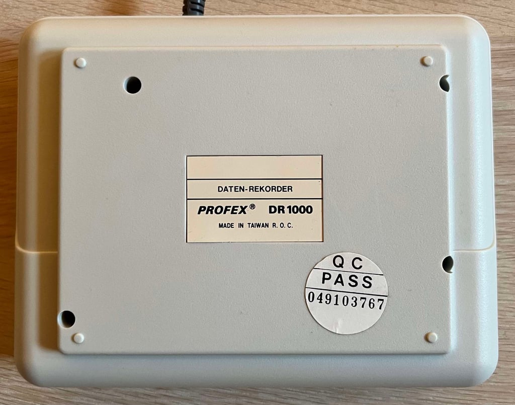
Datenrekorder (DR 1000)
Ser. No. 049103767
Starting point
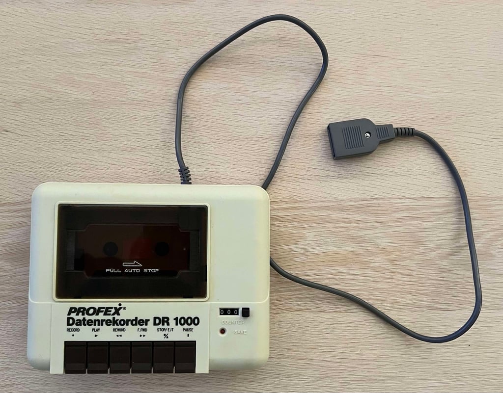
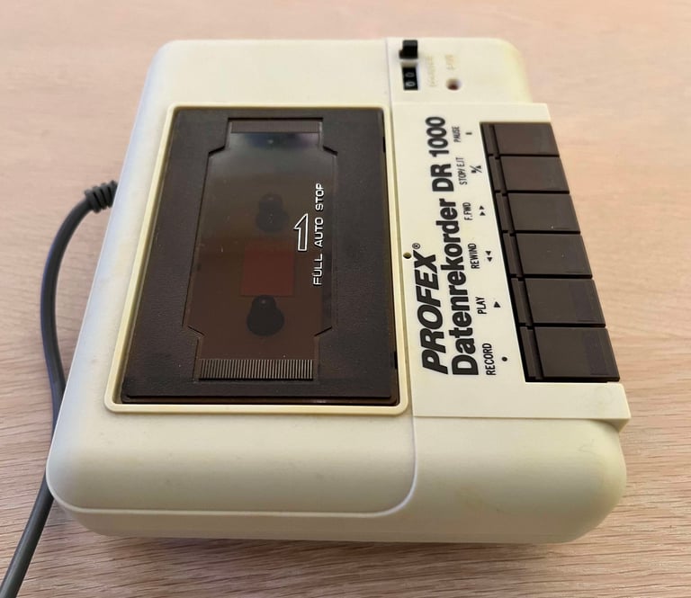
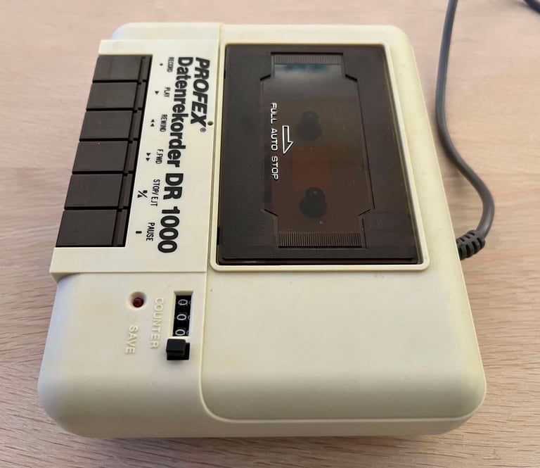
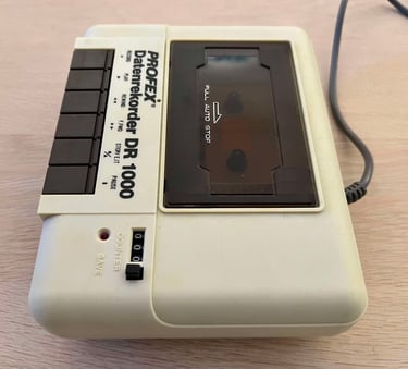
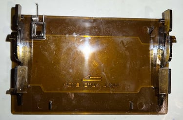
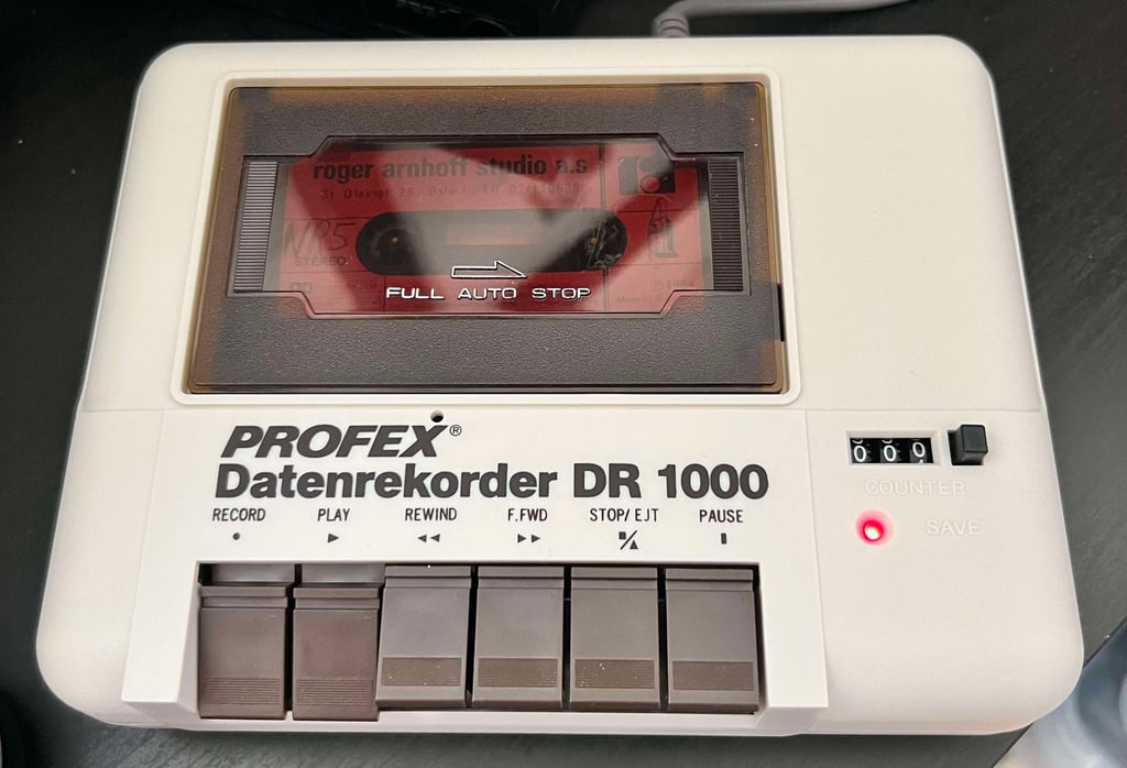
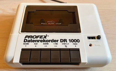
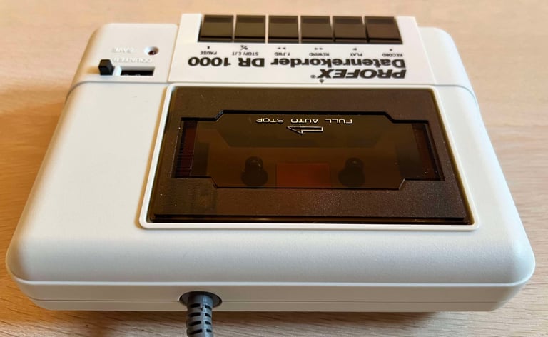
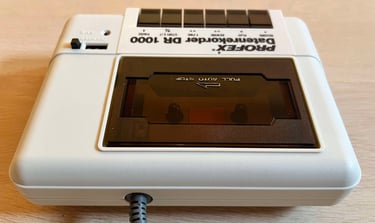
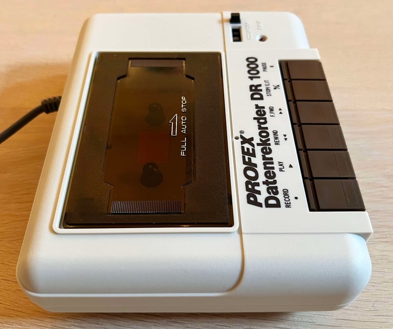
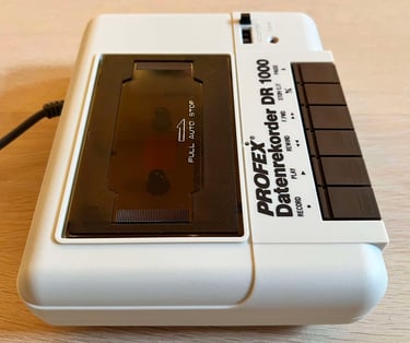
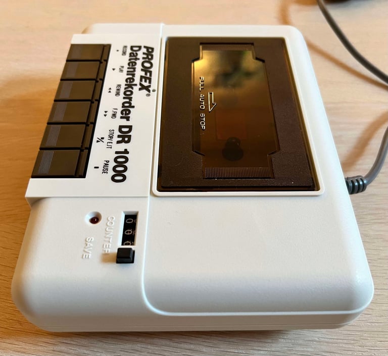
From the outside this Profex Datenrekorder seems to be in very nice condition, but it is here for some refurbish as it is reported to be "less co-operative". It is slightly yellowed, but it is marginal. There is hardly any dust or grease on the outside, and I can not see any sign of damage - only slight tear and wear.
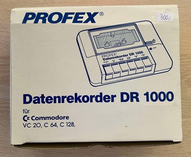
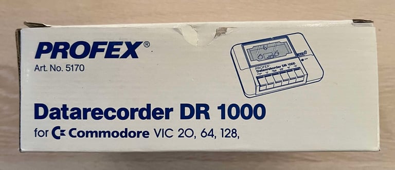
And how cool! The original box and user manual! This is the first time I have seen this for the Profex Datenrekorder DR 1000. Notice the price tag is still present saying "300,-" (I assume this is NOK 300).
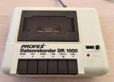
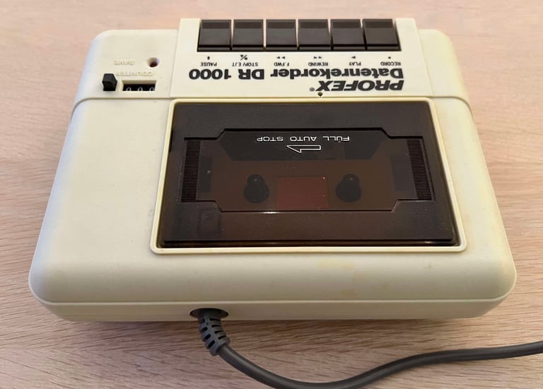
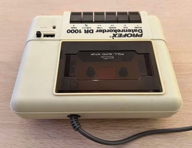
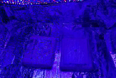
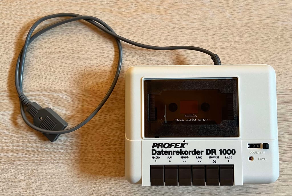
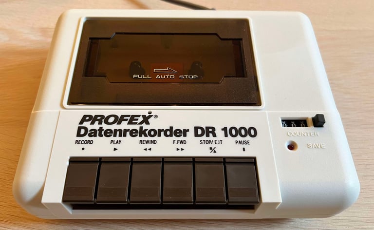
Below are some pictures of the Datenrekorder before refurbish.


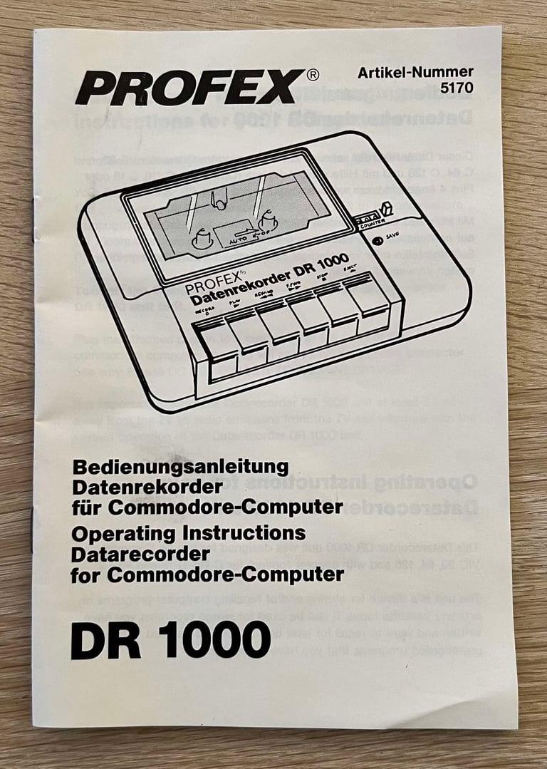
A scan of the user manual can be found here.
Refurbishment plan
To refurbish this DR 1000 datasette the plan is to:
- Clean and remove stains from exterior casing
- Retrobright top- and bottom cover
- Clean the interior mechanics
- Check cable and connector
- Check PCB for corrosion and replace old electrolytic capacitors
- Check, and if required, replace motor- and counter belts
- Check, and if necessary, adjust R/W head for optimal tape reading
- Check, and if necessary, adjust motor speed for optimal tape reading
- Verify datasette operation by testing
Note that these steps are not necessarily done in the order described above, and several of these steps are done in parallell.
Initial testing
Before the refurbishment commence a quick initial test of the datasette is performed.
As can be seen from the table above the datasette pass the initial testing. One thing I notice is that the datasette is quite noise when in operation, but I think this is quite normal. Earlier refurbishment of similar datasettes has shown the same noise.
Disassembly
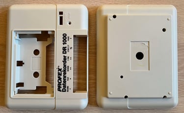
To start disassembly of the datasette, the four 3 x 13 mm Phillips screws at the bottom cover are removed.

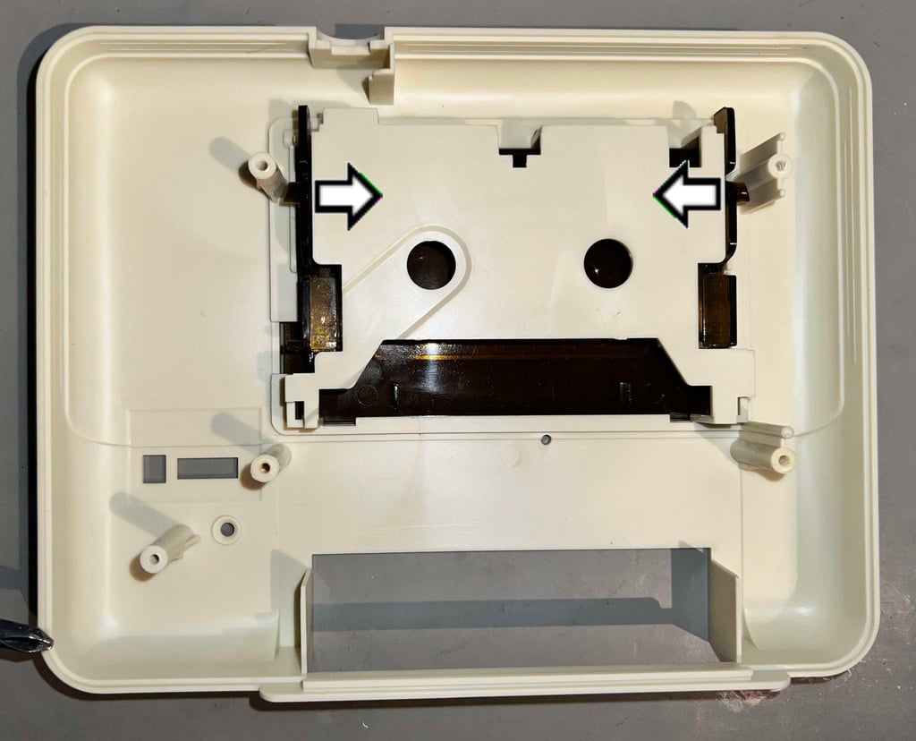
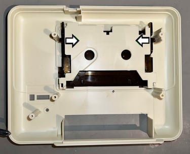
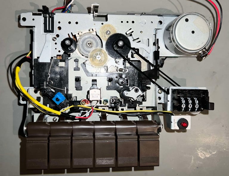
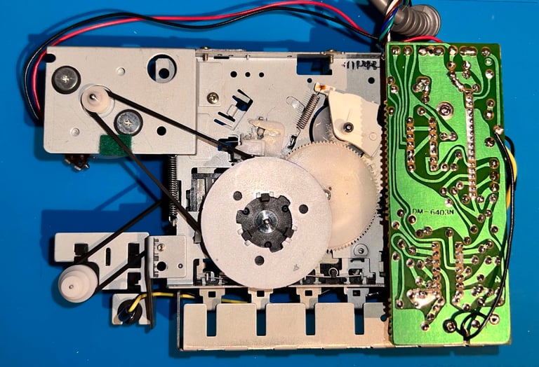
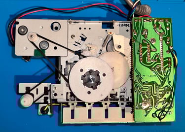
With the screws out of the way, the bottom cover is lifted off. The backside of the interior is exposed, and it looks to be in very good condition. There are some dust and grease, but it seems fine otherwise. Also, the motor- and counter rubber belts are not too worn. I still think they need replacement, but I have seen much worse belts than these.

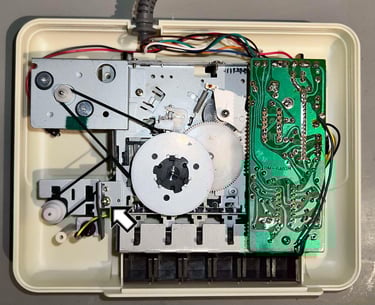
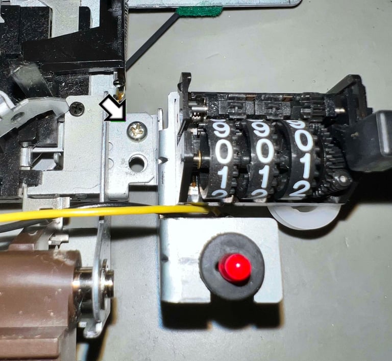
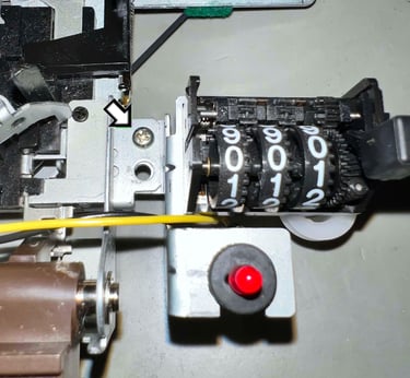
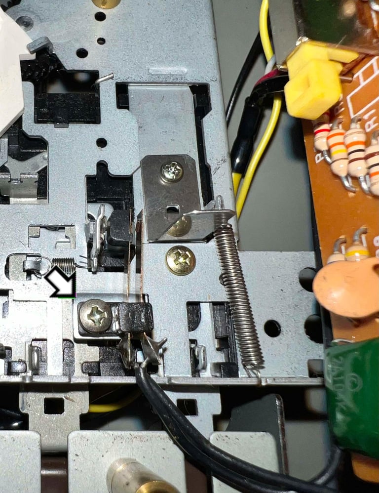
Before the mechanical interior can be removed from the top cover, the small 3 x 8 mm Phillips screw next to the counter belt needs to be removed. See arrow in picture above. When the screw is removed the interior is carefully wiggled out of the top cover.
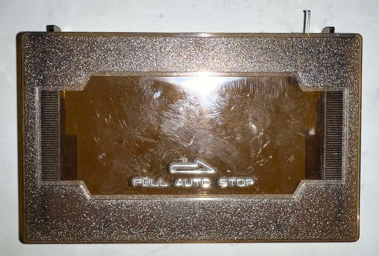
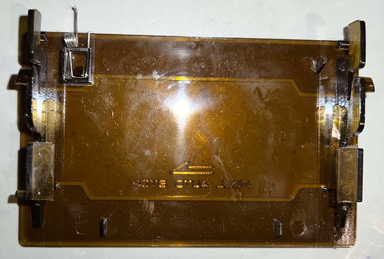
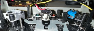
To remove the tape lid the two plastic pins (see arrows in picture above) are carefully pushed inwards. At the same time the tape lid is gently pushed outwards. You can also disassemble the small spring attached to the lid, but I choose to leave this as it is to avoid damaging it.

Exterior casing
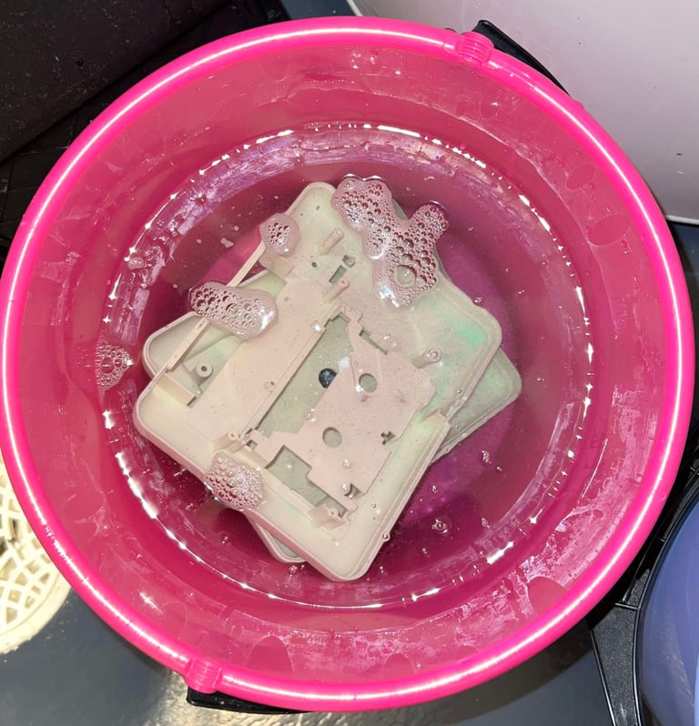
Before the covers and tape lid are cleaned, the stickers and labels are removed. By applying hot air (from a hair dryer) while at the same time using prying tools the stickers are removed from the covers. Some double sided tape will be attached to these when re-assembled.

With the stickers out of the way, the parts are placed in mild soap water for about 24 hours. This will remove most of the dust and grease.

After cleaning the top- and bottom cover are retrobrighted for about 12 hours; by applying 12 % hydrogen peroxide cream frequently on the covers, while at the same time exposing the parts for UV light. The parts are also wrapped in transparent cling film to make sure that the hydrogen peroxide cream does not dry out.
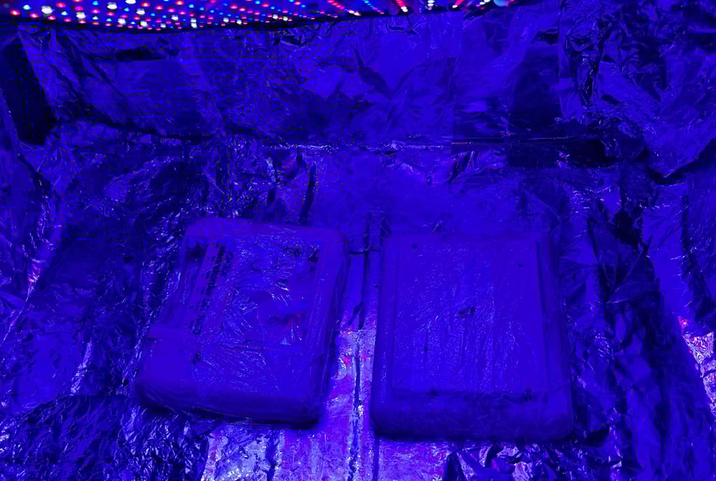
The covers looks really good after retrobrighting! All the yellowing is completely gone. There was some yellowing which was hard to detect from the photos initially, but all is now gone. Marvellous!

Interior mechanics
The interior is in very good condition. There are of course some dirt and grease, but it is quite marginal. Also, as previously mentioned the rubber belts (both for the counter and motor/flywheel) are in pretty good condition. They should be replaced anyway since they have been there for 35+ years, but it is interesting to see that they have not deteriorated too much.
Another interesting aspect of the PROFEX DR1000 "Datenrekorder" is that the interior, and also the exterior, is the same as e.g. the Noris DR1535. So the "Datenrekorder" is obviously a OEM where the interior (and exterior) is the same, but with different brands. I wonder who made these original?


Disassembling the keys
All the six keys are removed before cleaning the interior. To do this, the counter module is removed first. This module is mounted to the rest of the interior with a small screw which is removed.
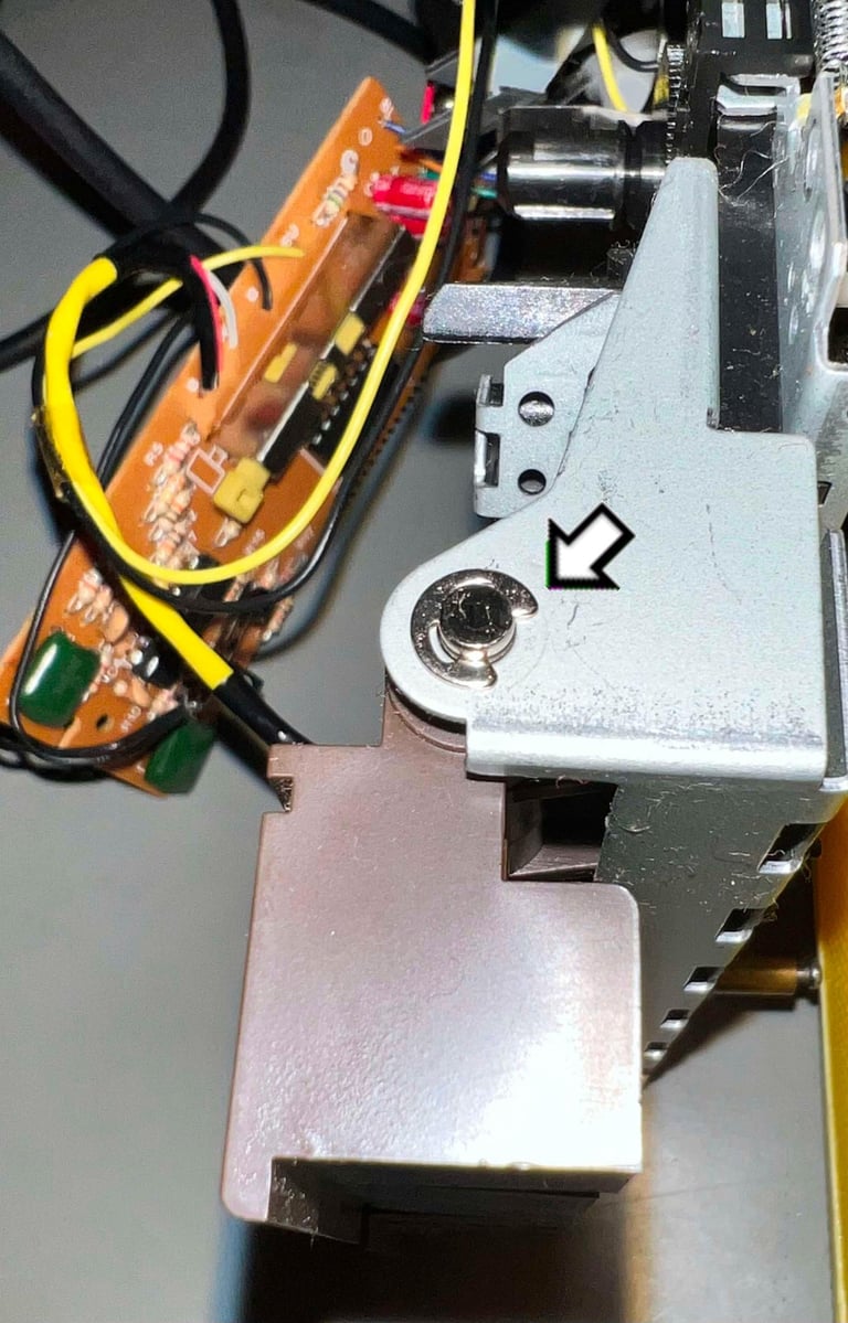
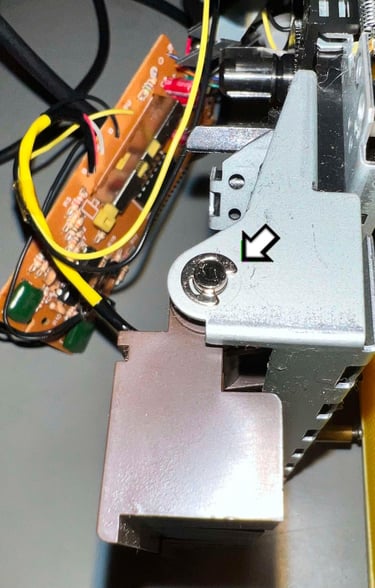
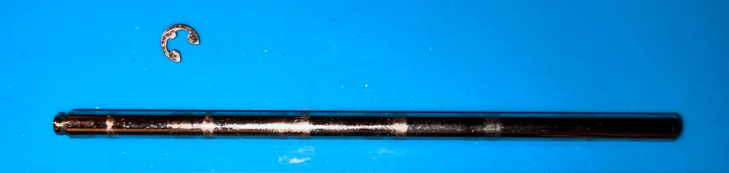
Next step is to remove the E-clip from the right hand side of the key shaft.
With the E-clip out of the way, the shaft is pulled out from the left hand side of the key row.

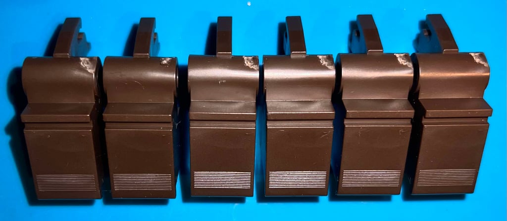
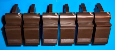
Each of the keys are cleaned individually with some mild soap water and glass cleaning spray.
Replacing the counter- and motor belt
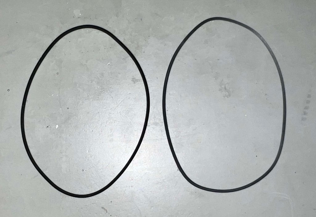
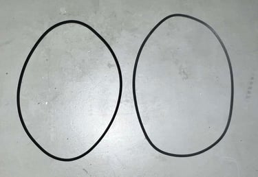
After 35+ years the belts are worn out. Not necessarily because of wear and tear, but the rubber will loose its natural elasticity. In stark contrast to 1530 datasettes, replacing the belts in the DR-1000 is very easy: simply pull them off. As can be seen from the picture below the old are quite deformed. Neverhtless, they are not too bad. I have seen worse.
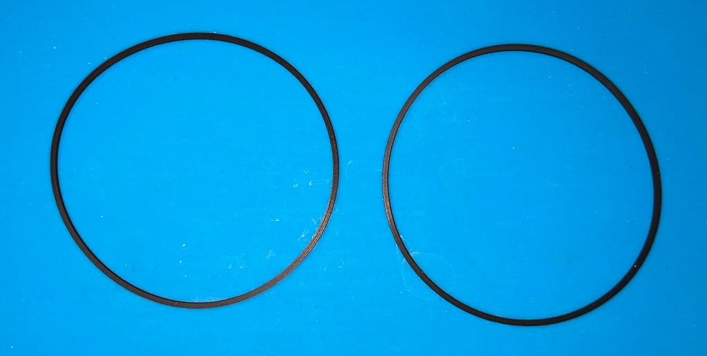
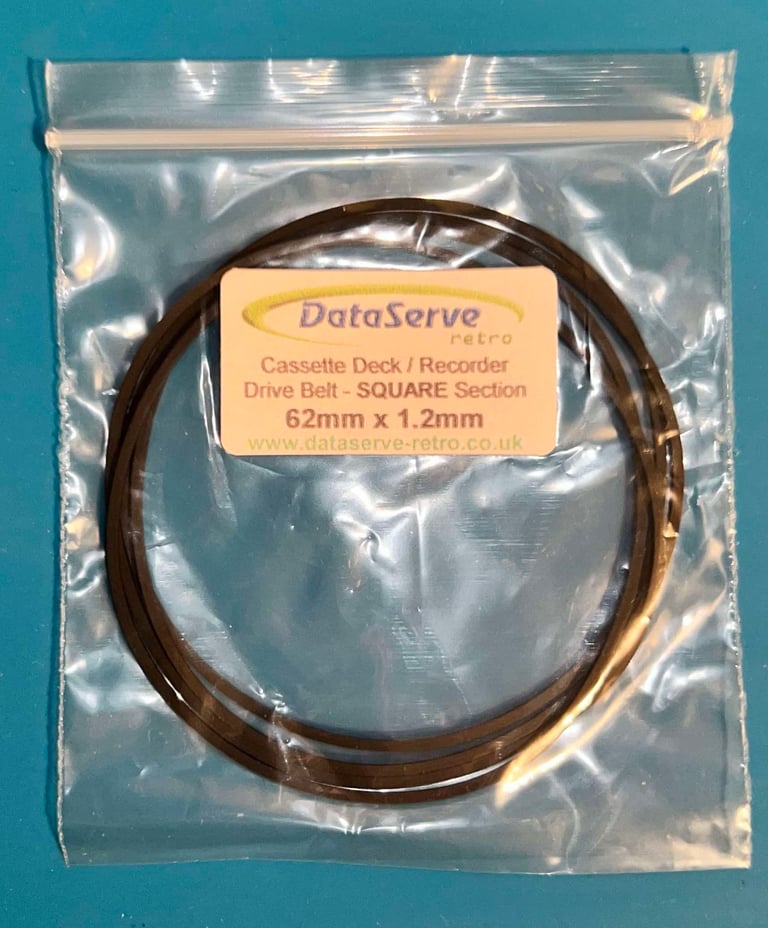
New quality belts are ordered from DataServe Retro. Note that these are special delivery 62 mm x 1.2 mm belts from DataServe Retro, and might not be part of stock. As can be seen from the pictures below these are fresh and elastic and fit the DR-1000 just perfect.


Cleaning the interior mechanics
There really is not much dirt and grease inside this Datenrekorder. Nevertheless, the interior is cleaned with some isopropanol and a Q-tip. Some areas require more attention:
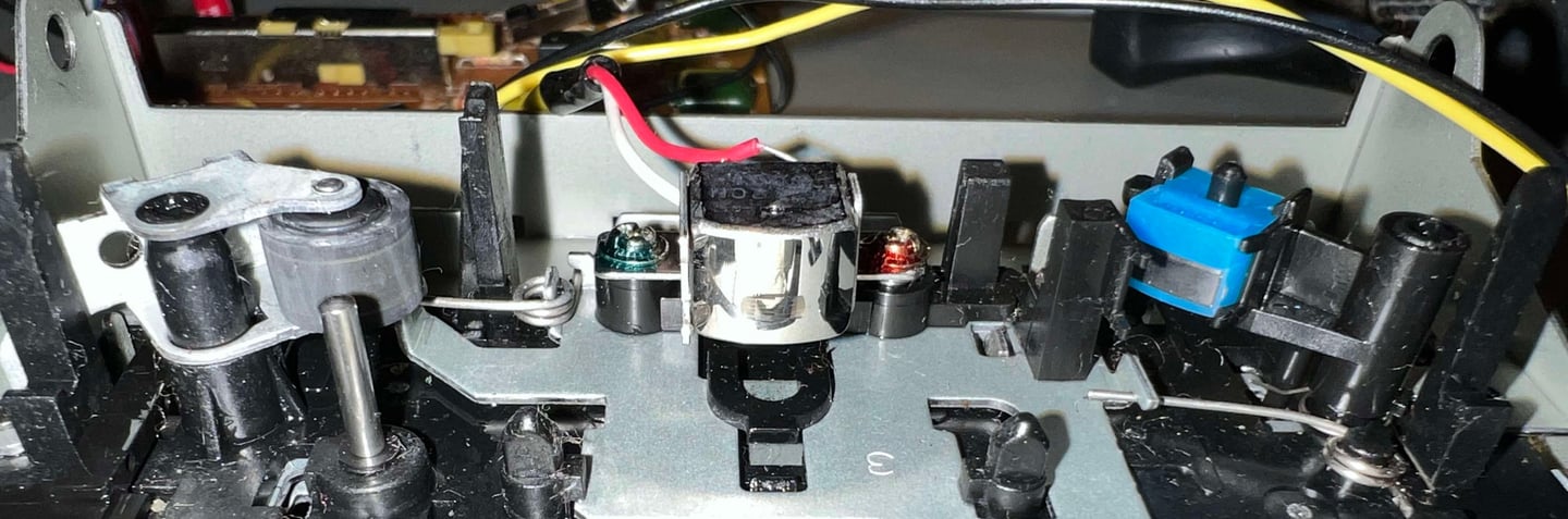
Pinch roller
Capstan
R/W head
These are cleaned throughly. Any dirt and grease in these areas can prevent the tapes by loading either by grease on the R/W head, or slippage of the tape between the capstan and pinch roller. Below are some pictures of the cleaned interior.
PCB and electrolytic capacitors
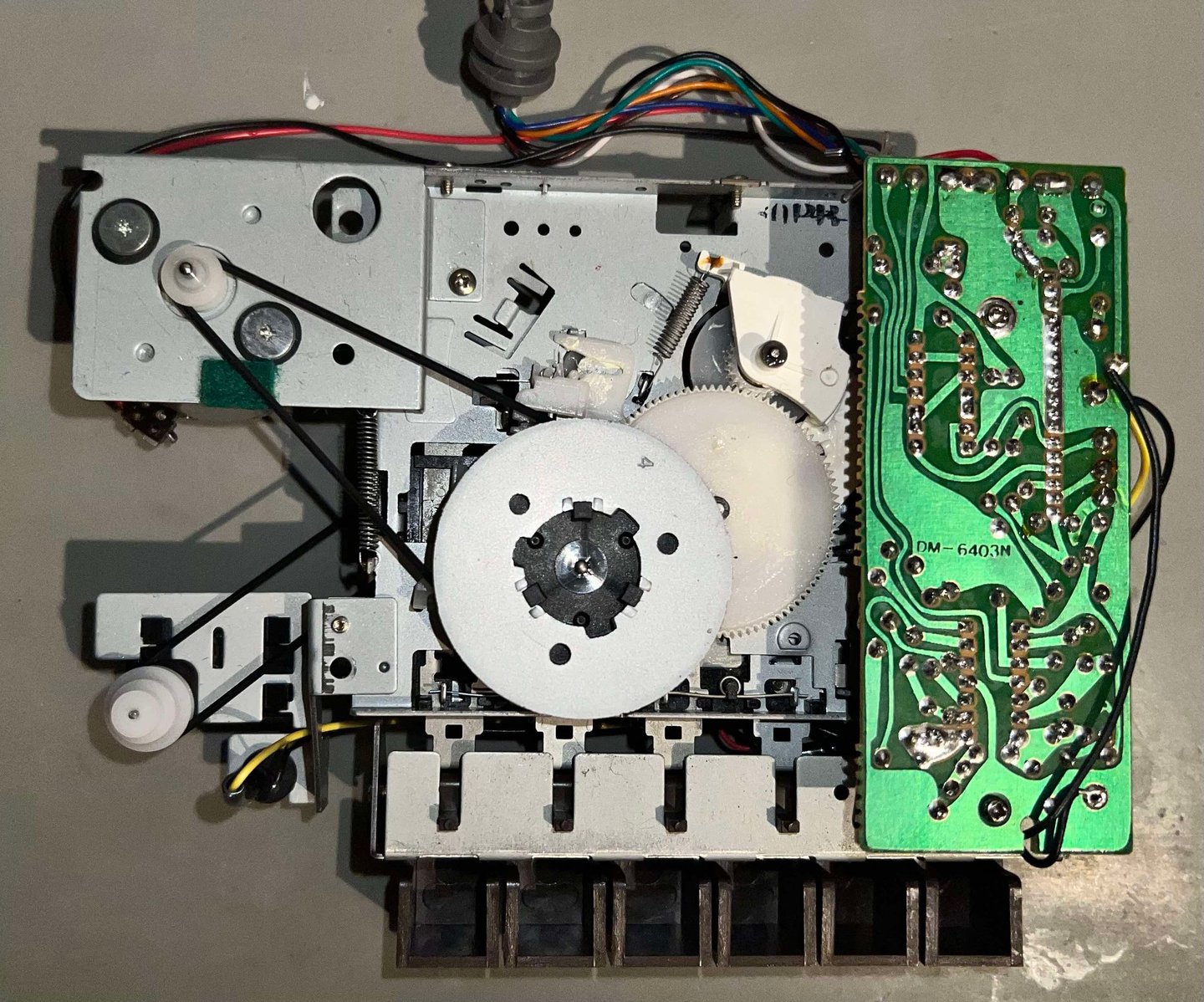
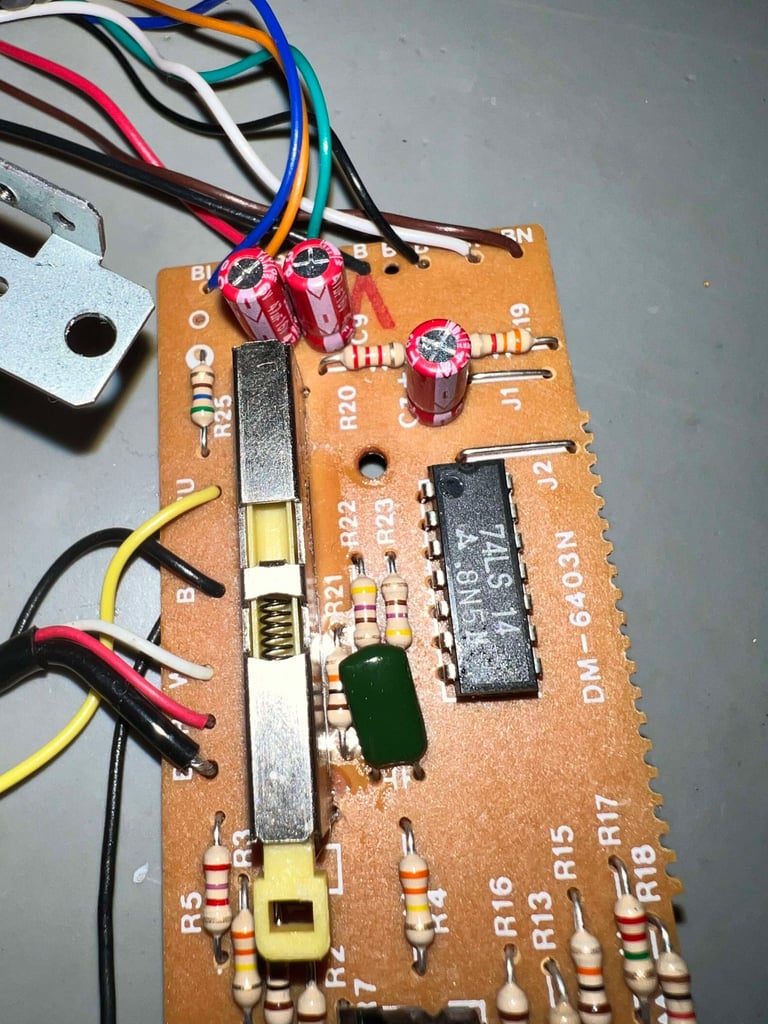
This PCB, version DM 6403-N, is in quite good condition. No sign of corrosion or damage, only some sticky flux residue but that is to be expected. According to the capacitor list there are 3 x 47 uF [16V] electrolytic capacitors on the PCB. The flux residue will be removed after new capacitors are installed.

Disassembly and visual inspection
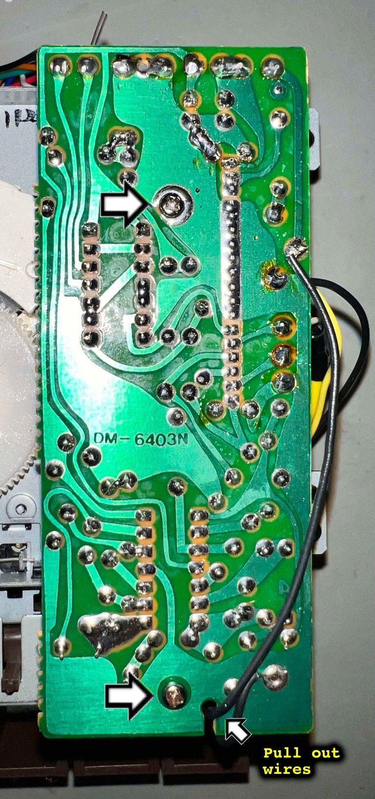
To remove the PCB from the interior mechanics, the two small machine screws are removed. Before lifting the PCB, the two black wires are carefully pulled away from the thin notch in the PCB (see picture above). The wires are bundled together at the back with a transparent rubber thread which is also carefully removed.
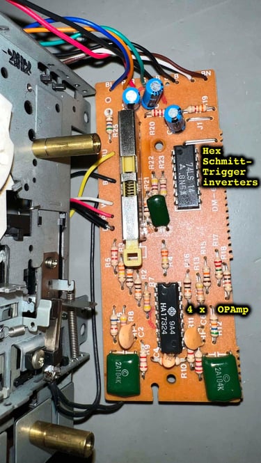
The key components of the DM-6403N consists of:
4 x Operational Amplifiers (OPAmp) [HA17324]
6 x Schmitt-Trigger Inverters [74LS14]
These components are used to amplify, and digitalise, the analog R/W signal. As can be seen from the picture below the front of the PCB looks to be in fine condition. No sign of corrosion or bulging capacitors.

It is good practice to remove the leaf switch from the interior also. This will make it easier to clean the leaf switch, and also to refurbish the PCB.

Replacing the electrolytic capacitors
As mentioned are there three electrolytic capacitors on the PCB. Although the look to be in ok condition, it is good practice to replace them with modern variants. In the picture below three new electrolytic capacitors from Wurth Electronics are installed. No pads or traces are damaged during the process.

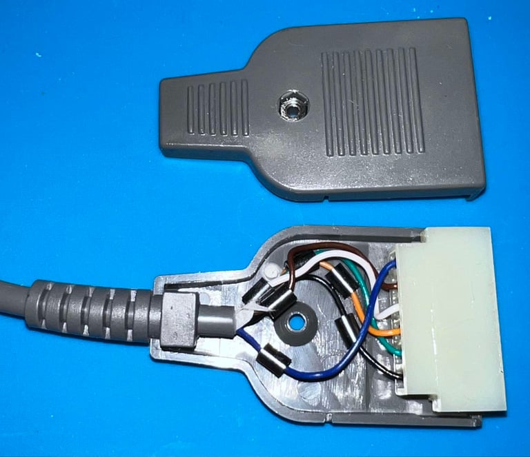
Cable and connector
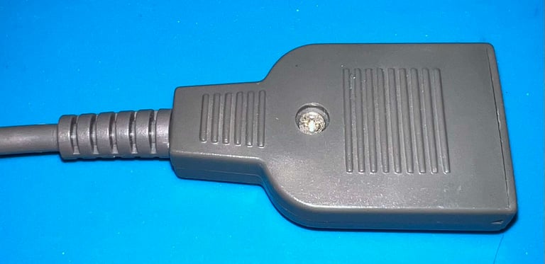
The cable, and the connector, looks in very good condition. In contrast to 1530 datasettes, there are no ground wire (which is not used anyway). The connector is disassembled and cleaned with contact spray.


Tape head azimuth alignment
In addition to replacing the belts it is crucial to check the tape head alignment and if necessary adjust it. Otherwise the datasette can´t load our beloved tapes without the notorious "?LOAD ERROR", or simply just fails loading.
A detailed article about how I align the tape head can be found here. As seen in this article I use both an oscilloscope and C64 software to do this operation in two stages:
The first stage I solder on two wires after the 2nd OP-AMP stage, connect the oscilloscope to these wires and then adjust the R/W head until I find the maximum amplitude on the oscilloscope. Note: if the amplitude appears to already be at maximum before tuning it is good practice to wait with further adjustment of the R/W head.
Second stage I use cassette-azimuth software running on a Commodore 64 while loading games from tape. In this second stage I do not do any adjustments - I only validate that the adjustment done in the first stage is correct.
Note that the datasette needs to be completely re-assembled when checking, and eventually calibrating, the R/W head alignment.
Stage 1 - Aligning the tape head with the oscilloscope
Two wires are soldered to the PCB according to the description found in the HOWTO article "Datasette head alignment" for DM-6403N. At first the signal amplitude seems a bit low at the 2nd OPAMP stage (according to what is normally detected at this stage). The amplitude is usually about 0.45-0.50 Volts, but here it is more like 0.35 Volts. But even after careful adjustment the maximum amplitude at this stage in the OPAMP chain seems to be in the 0.35 Volts range.
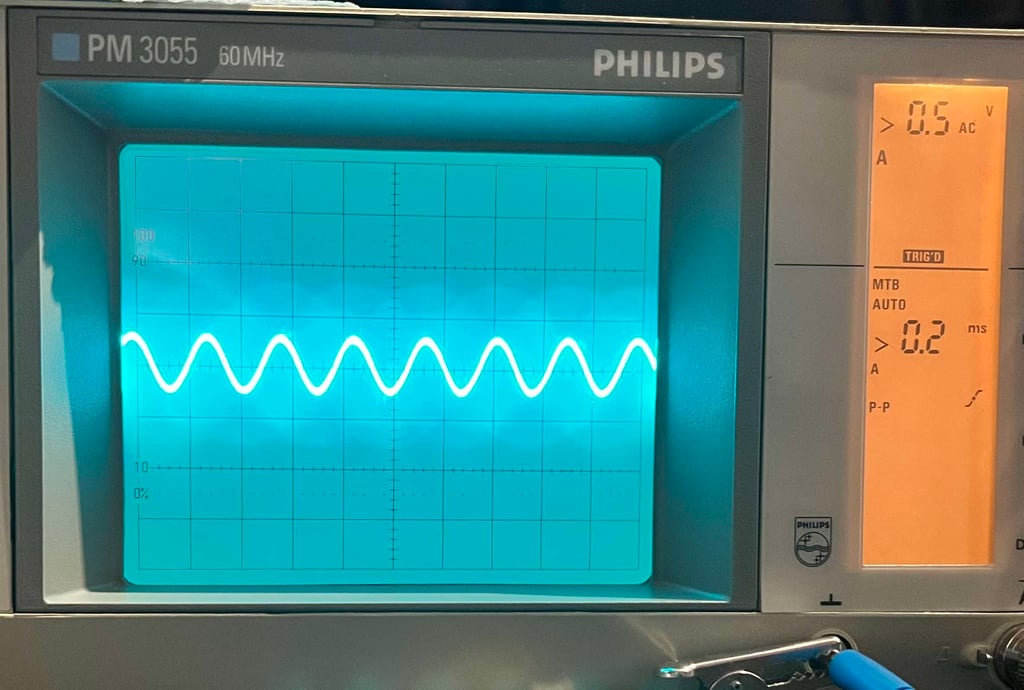

When doing the R/W azimuth head alignment it is crucial that the datasette (or Datenrekorder) is completely assembled with all screws installed, and the tape lid in place. Otherwise you risk a faulty alignment. But even with the amplitude at only 0.35 Volts it seems to work just fine, as can be seen from the video below. A small observation nevertheless, is that if I press the screwdriver with some force while doing the alignment, I see that the amplitude increases slightly. What that means I am not sure of, but if I encounter trouble when testing I will investigate this clue.

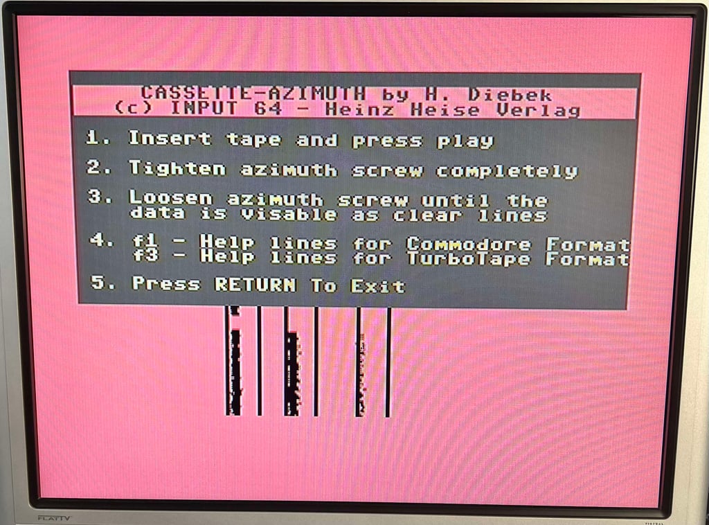
Stage 2 - Verification of the adjustment
To verify the adjustment with a second tool I use the cassette-azimuth software running on a Commodore 64. When the tape is loading there should appear three vertical bars on the screen. And the goal is that these three lines are as "solid" as possible. Note that these lines will never be completely solid, but the goal is that they are more or less straight vertical lines. If you have a misaligned R/W these lines will be scattered all over the screen.
I notice something interesting here. Although the lines are very straight and solid, they are a bit offset to the left hand side. I think that this could have something to do with the tape speed. This should not be a problem as the software in the Commodore 64 compensate for different tape speed, but it is something to consider if I get issues during testing.
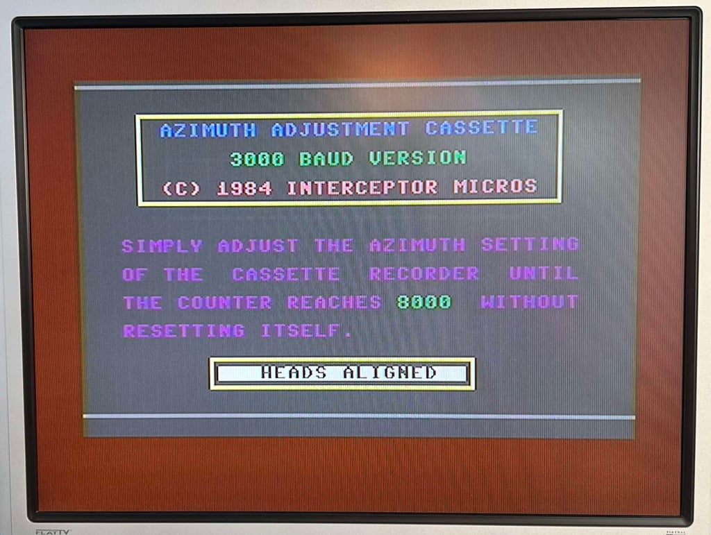
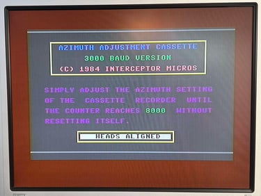
An additional bonus test
Recently I got this "Azimuth Head Alignment" tape from Interceptor Software. This is the second time I try this tape. It does looks to be in quite ok condition, but I am not really sure how well preserved it actually is. Also, I am not sure how accurate this is as a tool to say if the "heads are aligned" or not. The tape claims to do so, but I am not so sure...
Nevertheless, the tape loads and runs the test with flying colors.
Tape speed
Lately I have begun to check the speed of the tape playback. I am still a newbie in this area, but I think there is value in checking the playback speed.
The idea is smart, but simple:
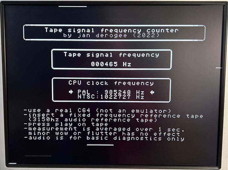
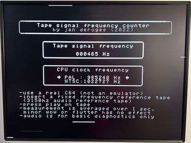
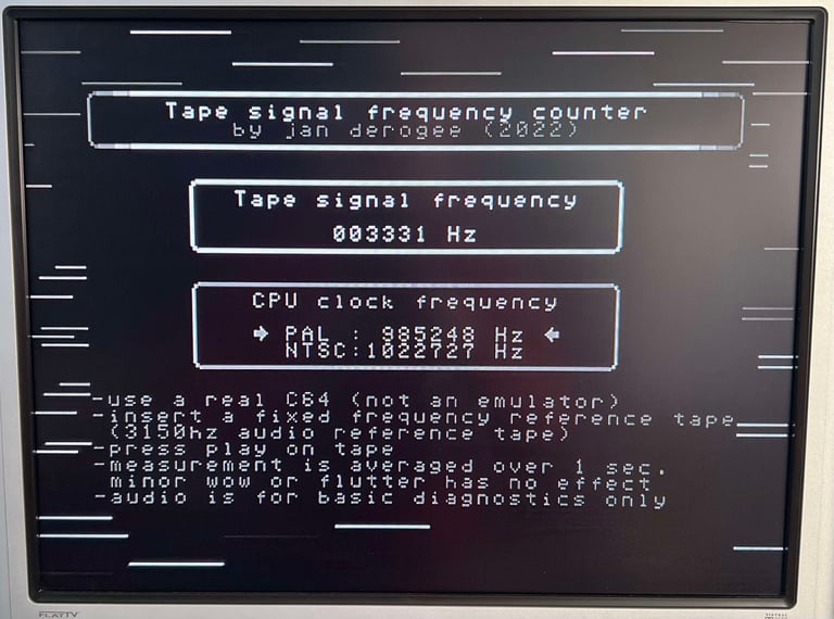
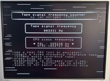
A professional Speed Calibration Audio cassette which contains a 440 Hz and 3150 Hz sinewave recording is loaded in the datasette. During playback of this tape a software (developed by J. Deorgee) reads the registered frequency on a Commodore 64. The idea is to adjust the speed until the recorded frequency, 3150 Hz, is measured.
Note that this great idea is not mine. The idea is based on a magnificent article by Jan Derogee and his Tape Frequency Counter software.
My experience so far is that the datasette (or datenrekorder) works best when the playback speed is in the range between 3150 - 3250 Hz. You could argue that the speed should be as close to 3150 Hz as possible, since this is the expected speed/frequency reading, but for reasons I have not understood yet I see that the tape deck works better with a slightly higher speed. I will continue to do these readings when refurbishing datasettes/datenrekorder to see if I can learn something!
As can be seen from the picture below the speed is bout 3330 Hz/465 Hz. It is a bit high, but I will not do any adjustment (yet). I am still collecting data and results of these measurements. But if the testing fails, this could be an interesting result to investigate further.
Testing
Playback
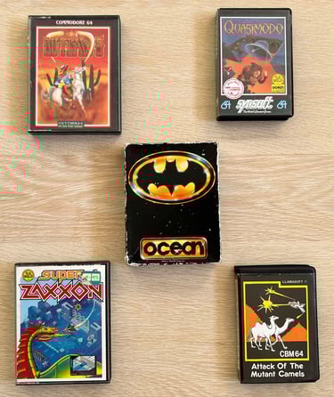
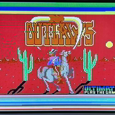
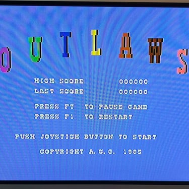
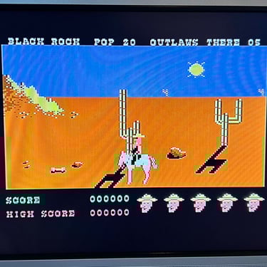
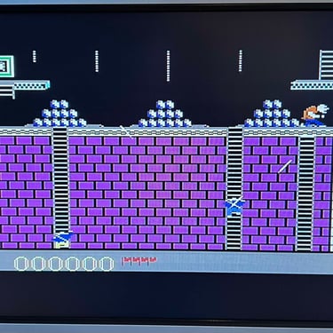
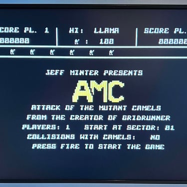
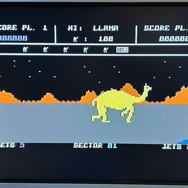
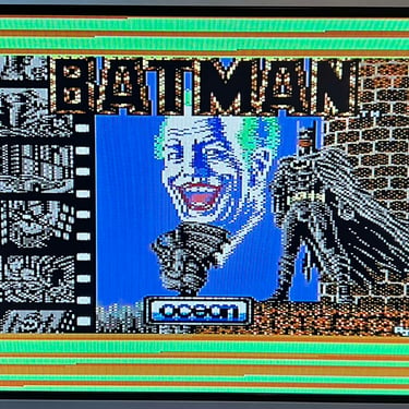
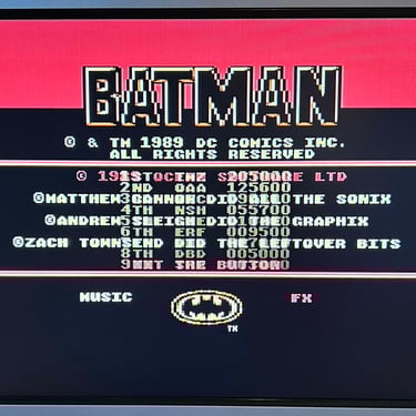
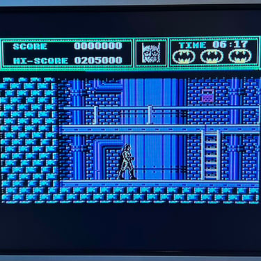
To make sure now works as it should I select five original C64 games to be used for testing. Even if these games are old and worn the load without any problems at all. Below is a picture gallery from the testing.


Recording
The saving functionality is also checked and verified. A small BASIC program is made and the SAVE command is used (and then the program is re-loaded). The LED is also on while recording is in progress.

Final result
"A picture worth a thousand words"
Below is a collection of the final result from the refurbishment of this datasette. Hope you like it! Click to enlarge!

Banner picture credits: VİLDAN-ATİLA GÖKÇEN CALCULATOR & COMPUTER & RETROTECH MUSEUM