

The Arcade Turbo
Starting point
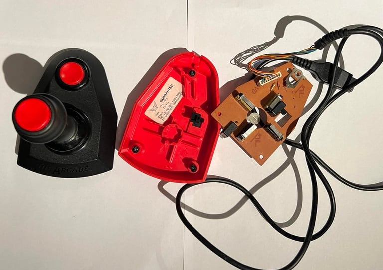
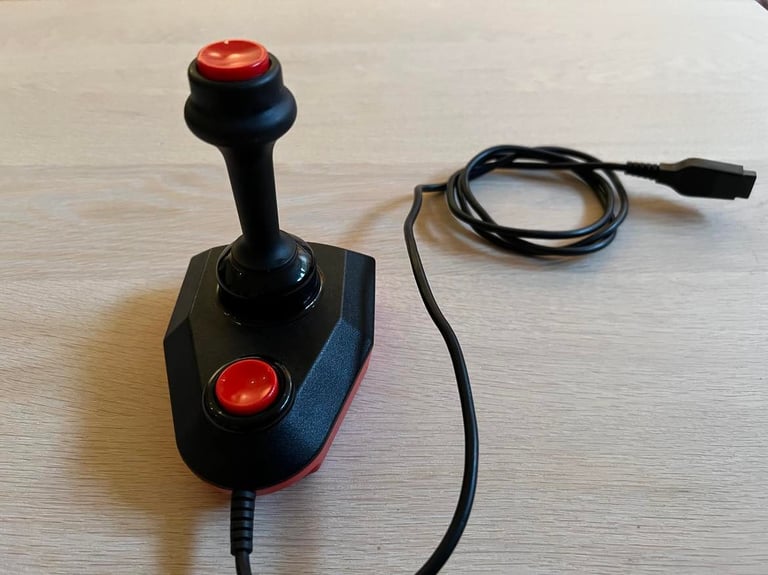
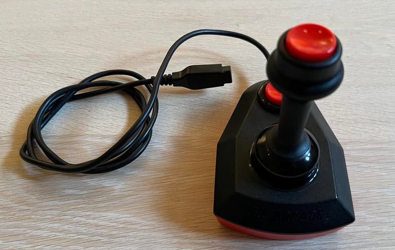
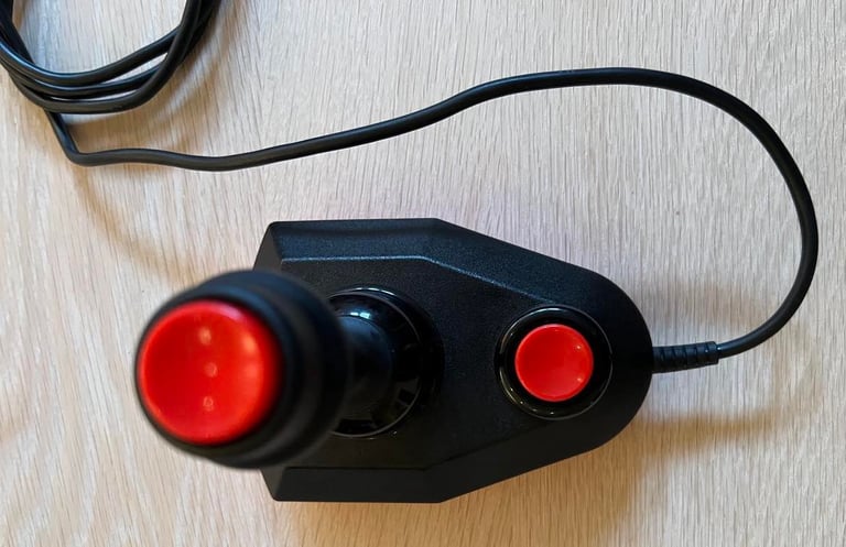
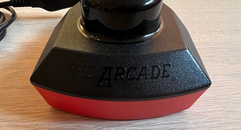
This is the famous "The Arcade Turbo" joystick - with two selectable fire buttons - one in the front and one on the top. Seen from a refurbishment perspective the joystick doesn´t look too bad, but it is pieces. The top- and bottom cover of the chassis are already "disassembled" due to broken pieces. And I have no idea if the joystick even works in regards of cable connectivity and micro switches.
Nevertheless, I think this joystick can be repaired back to it´s original glory. This is one the best quality joystick made for the Commodore 64 (and Atari I assume) so I hope this will be a success. Below is a picture of the state of the joystick before refurbishment.

Refurbishment plan
To refurbish this joystick the plan is to do this trough the following steps:
- Clean, and remove stains from, chassis and all parts
- Repair broken chassis parts
- Clean the PCB
- Check cable and connectivity
- Verify joystick operation by testing
Exterior chassis
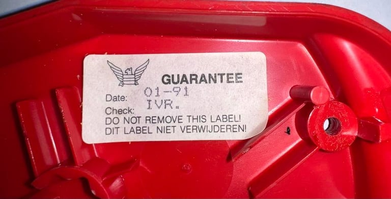
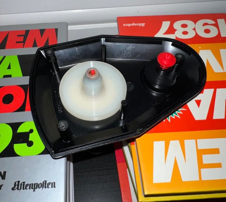
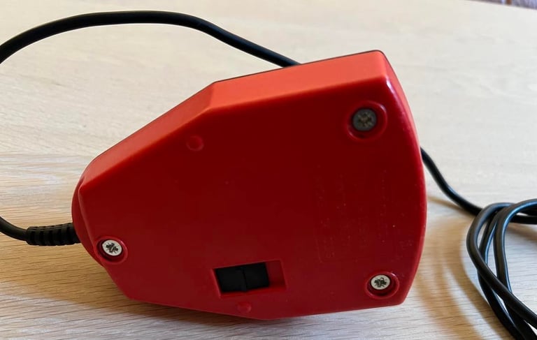
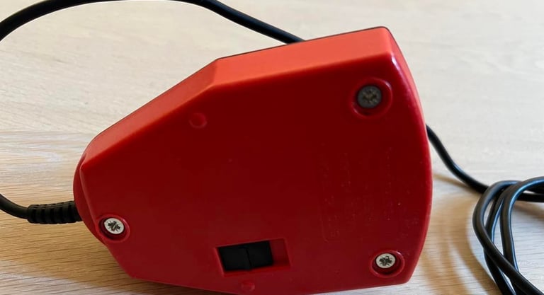
The top- and bottom cover are quite dirty so I will clean these with some luke warm water and mild dishwashing soap. But before I do that I carefully remove the broken stand-offs (and note which-is-which). Also, the little sticker inside the joystick is carefully removed so that it´s not broken by liquids. From the sticker I see that this joystick is (probably) from January 1991 - so it´s over 31 years old! (It says "Do not remove this label!" but I hope I can be forgiven...)

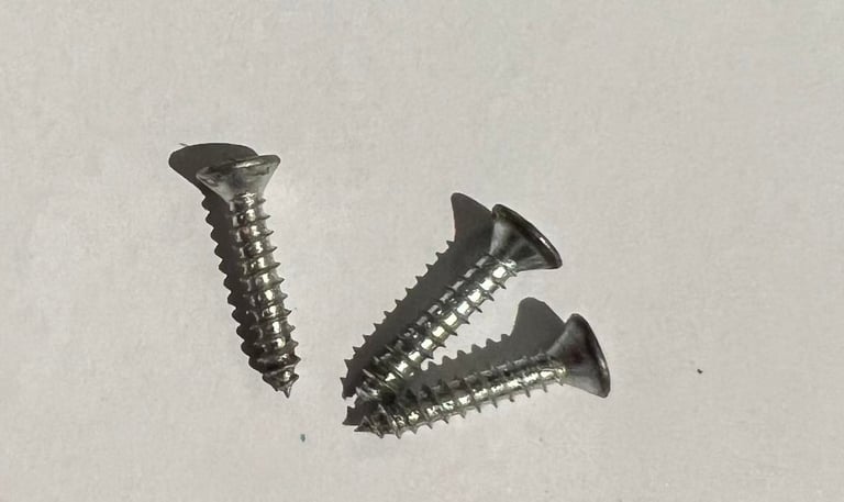
It is easy to see why the three stand offs are broken. Instead of using the fine original screws some thick coarse wood screws have been used (see picture below). I guess it´s due to the thickness that the stand off have broken. Nevertheless, the stand offs seems to be split apart in a place where they can be fixed with some epoxy glue. As long as there is a "grip" on the top cover this should be fine.
The result from cleaning is promising. It is cleaned with soap water first, and then polished with some glass cleaning spray.
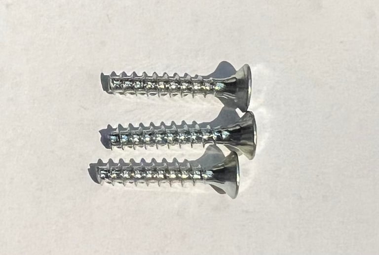
As mentioned the three stand-offs are broken. But I´m not too worried about that since the main part of it is still present on the top part of the chassis. So I glue these with some epoxy glue and let it harden for 48 hours. The plan is to find some replacement screws which is more suited for this joystick than the previous coarse wood screws. Below is a picture from the gluing process.
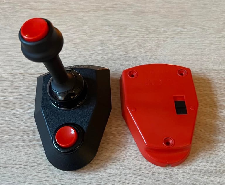
Both fire buttons in the chassis are lubricated with some silicon grease (spray). This is so that these buttons will move freely under operation. Three new screws are made by using 3.5 mm conical screws which are cut to the correct length. Also, the screws are lubricated before fastening to ease the tightening process.
The cool Suzo guarantee sticker is put back in with some double sided tape.
Interior electronics
Interior PCB looks undamaged and free from corrosion. All four microswitches also appears to be functioning as expected. First thing before testing the PCB and the connectivity is to clean the PCB with isopropanol - and all the microswitches are sprayed with contact cleaner.
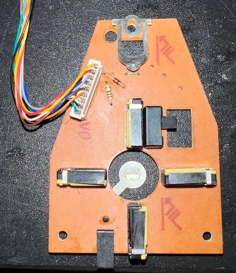

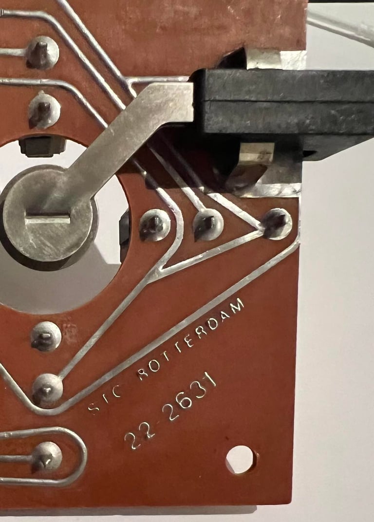
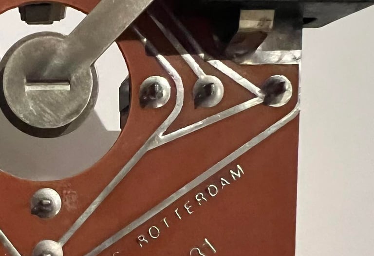
I´ve refurbished The Arcade Turbo before, but I notice something different with this one. It´s normal that all nine wires are soldered onto the PCB, but that some of the wires are not used. The minimum numbers for a joystick without auto-fire is to have six wires in use, but this joystick has with wires in use! Below is the pinout for a standard 9 pin D-Sub connector used for the Commodore 64 (and Atari I believe). The pinout is seen from the connector on the main board of the C64.

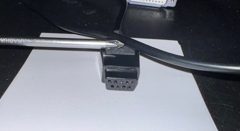
I start with checking the connectivity from the inside of the joystick to the connector. I use the "beep" functionality on the multimeter to make sure that the resistance is the cable is both low enough and not broken to make sure all wires are ok (which the pass the test).
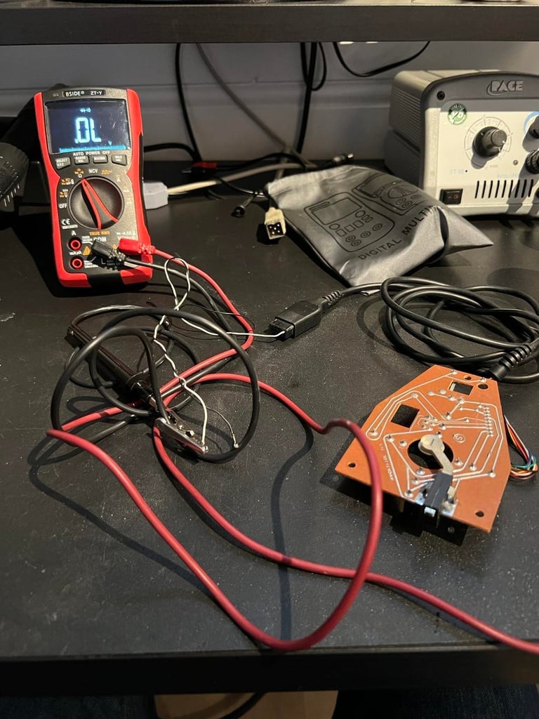
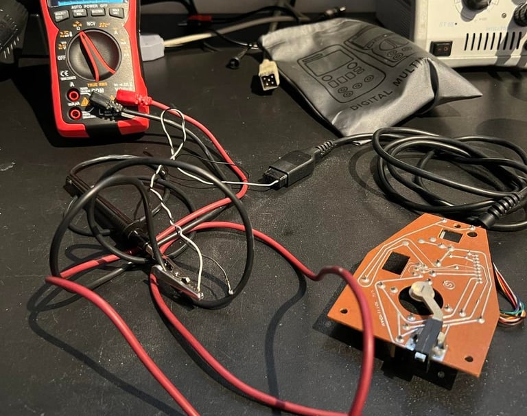
After studying the PCB I see what is different in this joystick compared to the previous I refurbished. Pin # 9 (marked as "POT AX" in the schematics above) is used in the joystick. The 9th pin is connected to the anode side of a diode, and where the cathode is connected to +5V. Why? I have no idea. I can only guess that this is something that is done as an improvement to the PCB to make sure that it works for all versions of Commodore/Atari. Below is a small sketch showing the wiring diagram (A and B represents the two different fire buttons). The 9th pin is normally used for paddle / touch tablet input on Commodore / Atari systems.
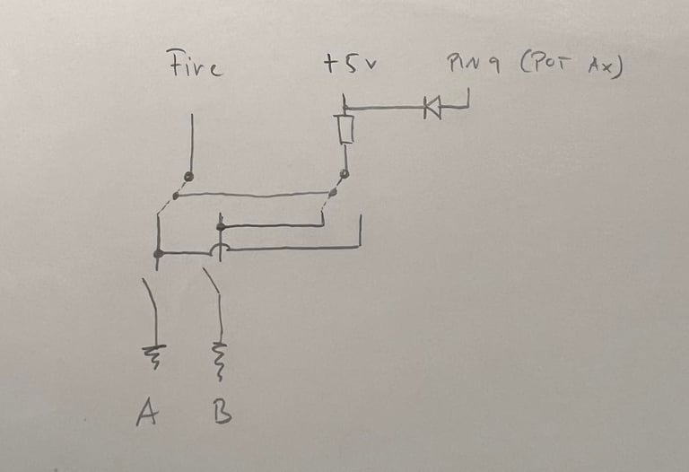
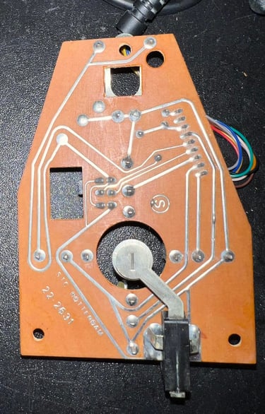
Last thing I notice is that the revision of this PCB is "22-2631". Compared to the previous joystick refurbished this was "22-2630". So, my conclusion is that this extra diode is only to make sure that this joystick works 100 % on all Commodore/Atari systems. An small upgrade for the previous version that is.
Cable
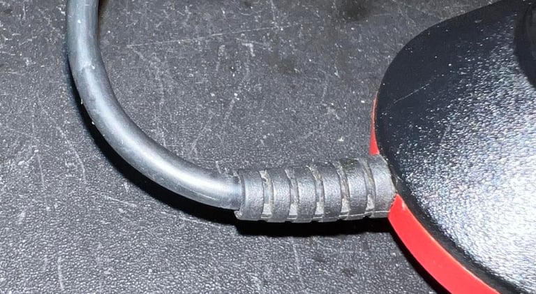
The cable have been testet thoroughly (see previous chapter), but I also inspect the connector pins and the strain relief. Both seems to be in good condition. The connector is sprayed with contact cleaner and inserted/removed for a few times to clean the pins. This joystick does not need any new cable as far as I can see.
Testing
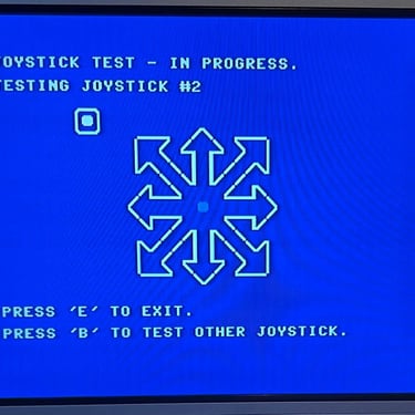
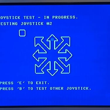
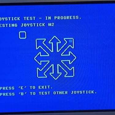
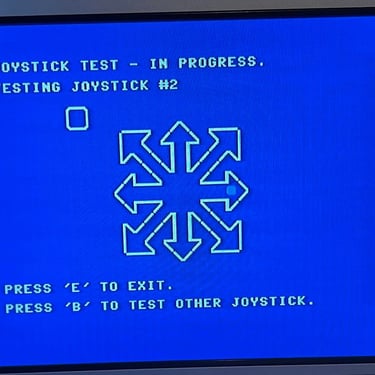
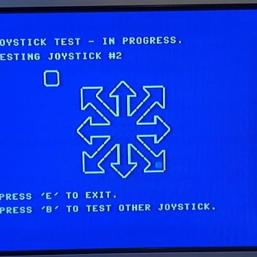
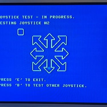
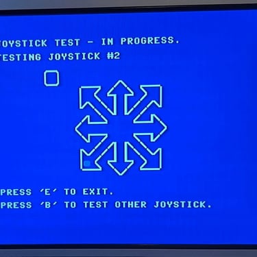
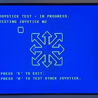
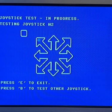
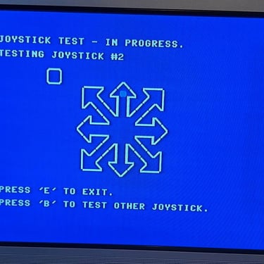
After the joystick is re-assembled it is tested with a known working Commodore 64. With this Commodore 64 I use the program "64 Doctor" which is a simple, but very effective tool to verify that all directions and fire buttons work as they should. The joystick works as it should - all directions and fire buttons are ok.
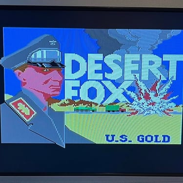
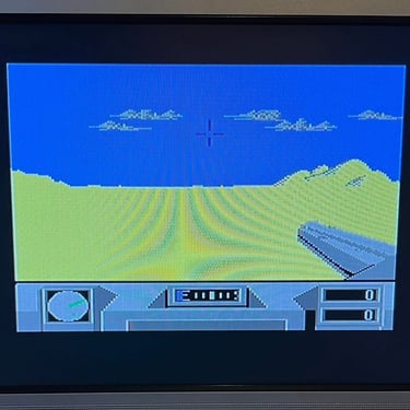
A final test is done by playing some good old Commodore 64 games! Here´s a screenshot from the game Desert Fox from U.S. Gold!
Final result
"A picture worth a thousand words"
Below is a collection of the final result from the refurbishment of this C64. Hope you like it! Click to enlarge!

Banner picture credits: SdeVries