

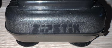
ZipStik
Starting point
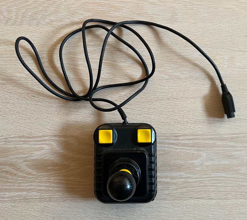
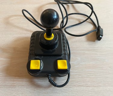
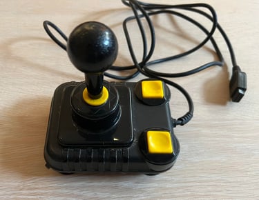
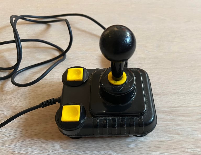
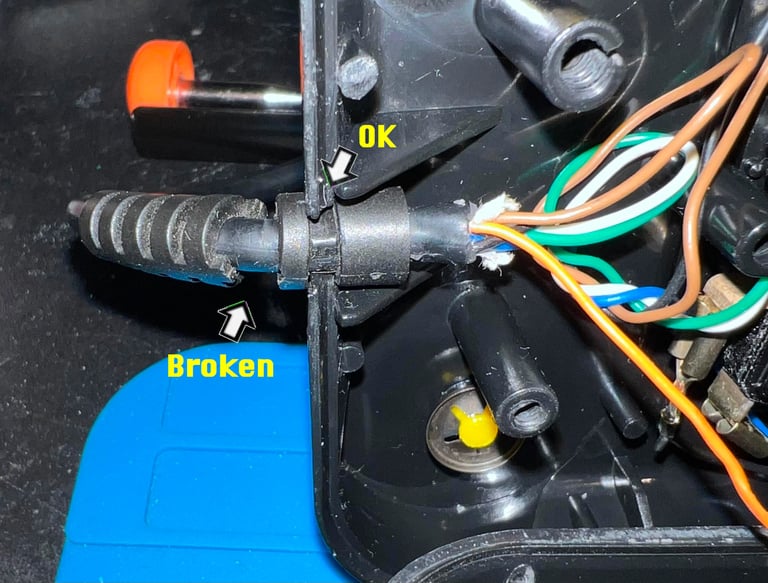
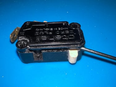
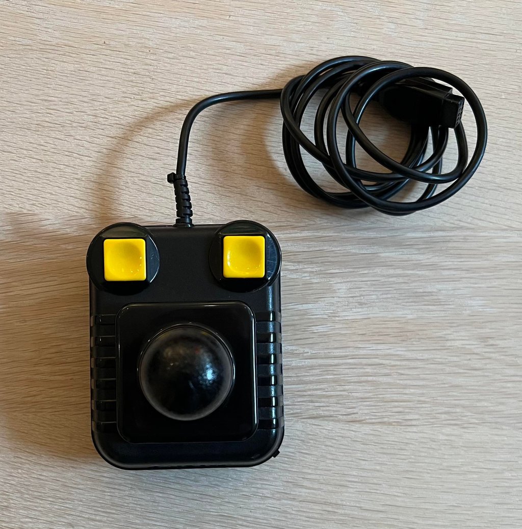
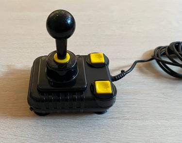
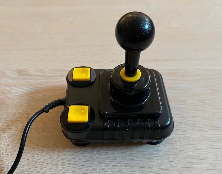
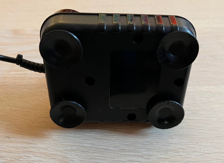
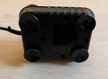
This Zipstik joystick looks not too bad. It is quite dirty and the cable looks a bit suspicious, but otherwise it seems intact. Notice that the strain relief is partly broken. There is the well known "clicking" sound when pressing the fire buttons and moving in the LEFT/RIGHT/UP/DOWN direction. Also, there is an auto fire button which also appear ok. Some of the rubber feets have some odd looking marks. Almost like someone has tried to chew on them... which is highly unlikely. I guess it could be due to some chemical / mechanical reaction with the surface.
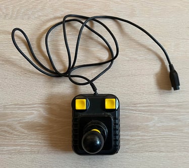
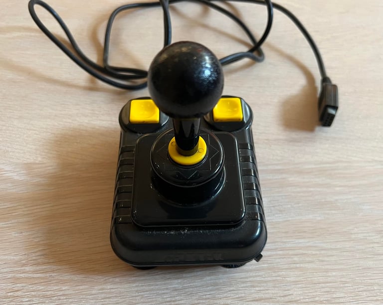
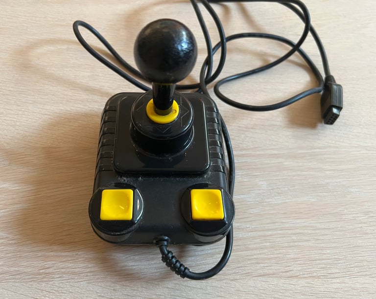
Nevertheless, if the the looks are not too bad, I have no idea if this Zipstik works or not. Below are some pictures of the joystick before refurbishment.


Refurbishment plan
To refurbish this joystick the plan is to do this trough the following steps:
- Clean, and remove stains from, chassis and all parts
- Clean and check the microswitches (and repair if required)
- Clean and check the autofire
- Check connectivity (and repair if required)
- Verify joystick operation by testing
Opens it up...
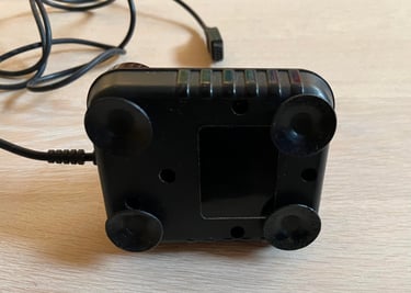
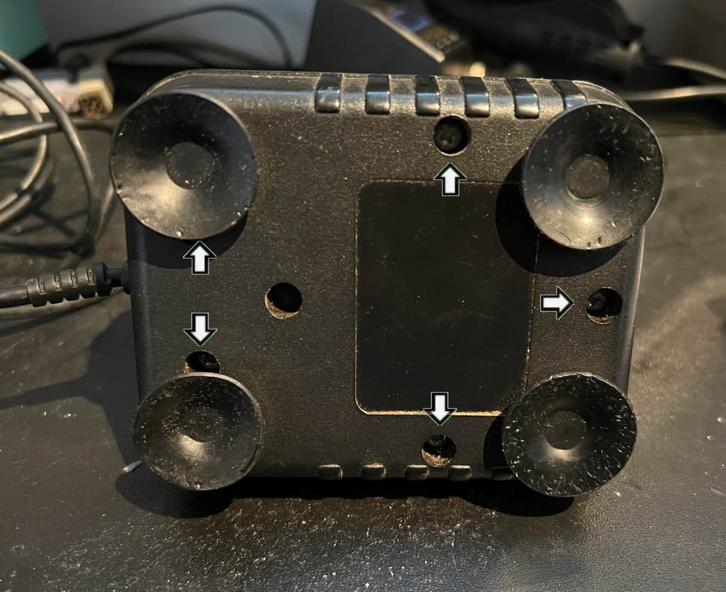
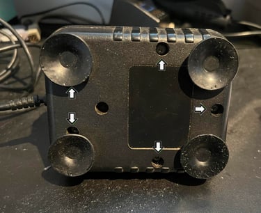
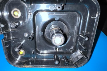
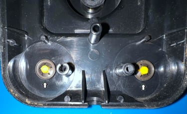
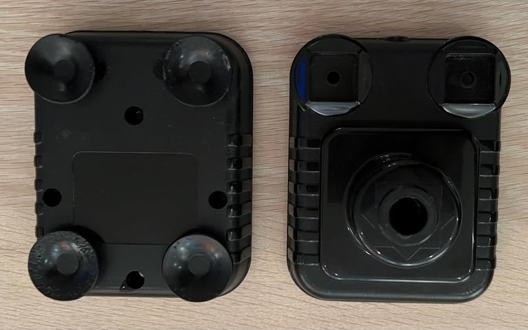
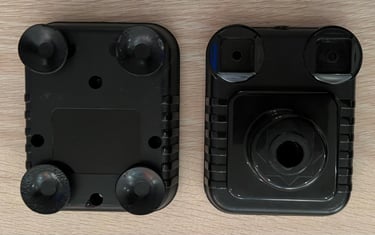
To start disassembly of the joystick the five screws at the bottom of the joystick are removed first. See arrows in the picture below.
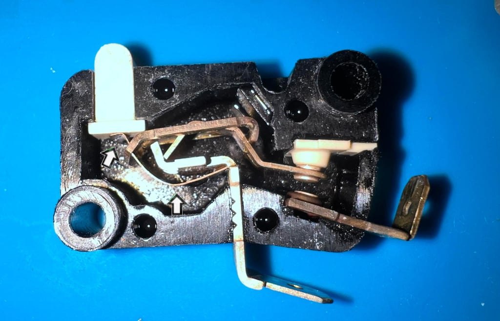
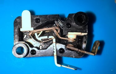
The joystick is carefully opened and the interior is revealed. As can be seen from the picture below the interior is quite dirty, but it looks to be mostly undamaged. There is some small damage on one of the plastic screw "towers" (see arrow). But this is something I think can be repaired, and should not affect the functionality of the joystick in any way. Notice that four of the microswitches (for the directional UP/DOWN/LEFT/RIGHT) are covered with some strange looking dust.
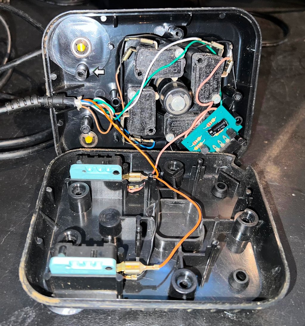

Before disassembling the shaft and fire buttons, the autofire and all microswitches are carefully lifted out of the top cover.

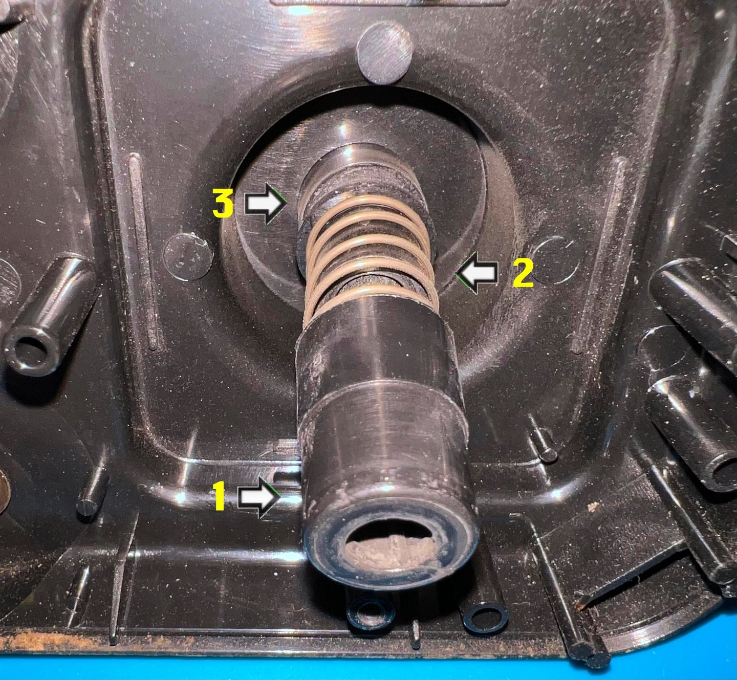
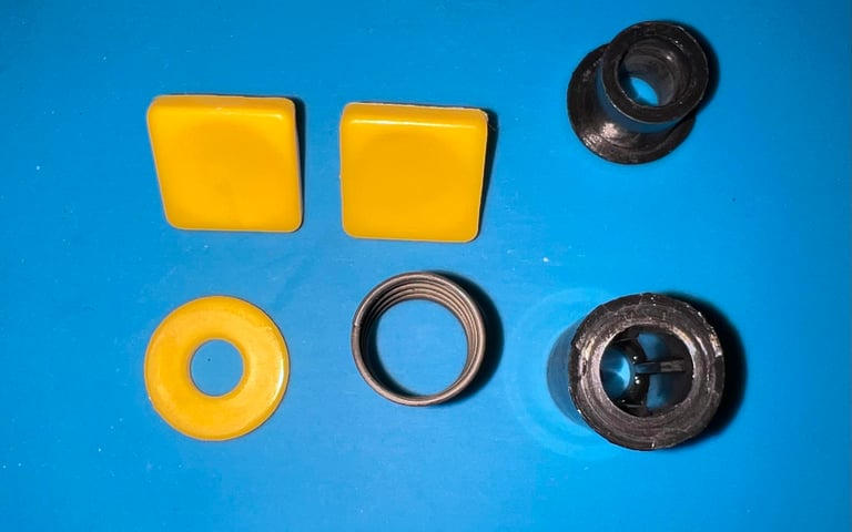
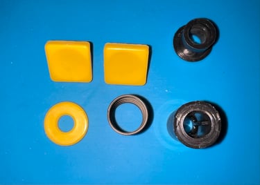
To disassemble the joystick shaft the e-clip is removed first (see picture below). Then the two plastic parts (1 and 3) and the spring (2) are removed before the joystick shaft is slid out of the bottom cover.


Both fire buttons are also removed. With a pair of pliers the round metal clips are removed from the yellow fire buttons.

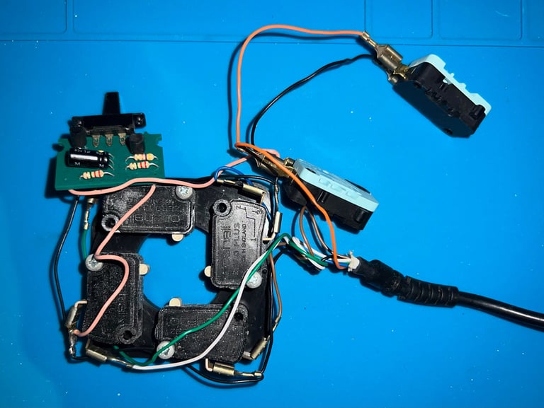
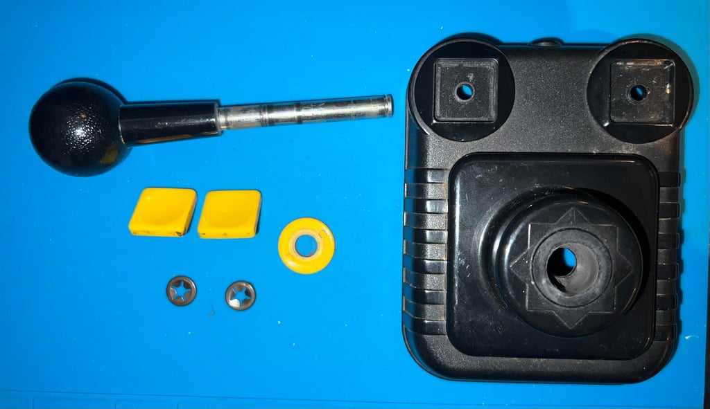
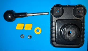
Below is a picture of all the parts - before cleaning and lubrication.
Exterior casing
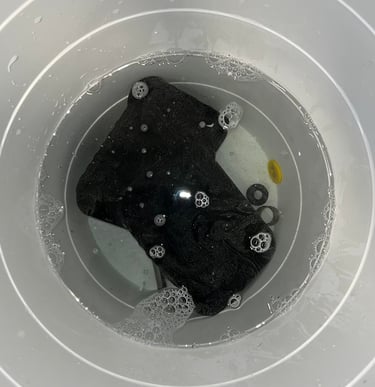
The top- and bottom cover is quite dirty, and that is also the case for the rest of the parts. Everything is placed in a bucket of mild soap water for about 24 hours.

Most of the dirt is gone after this long bath. But the last remaining stains are removed with some isopropanol. The result is very promising.
Lubricating the parts
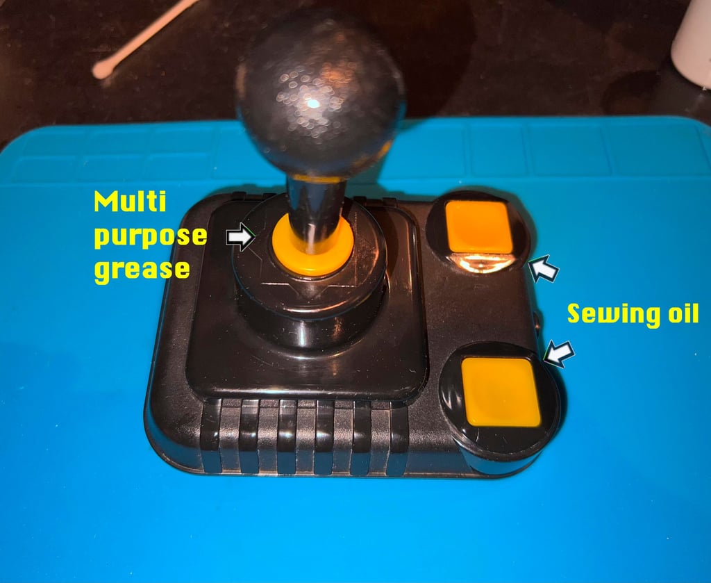
To both avoid squeaking noises and give a more smooth joystick operation the parts are lubricated. The shaft is lubricated with some (not too much!) multi purpose grease, and the small pin and walls of the fire buttons are lubricated with a small drop of sewing oil.

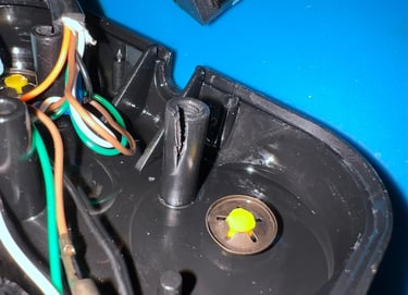
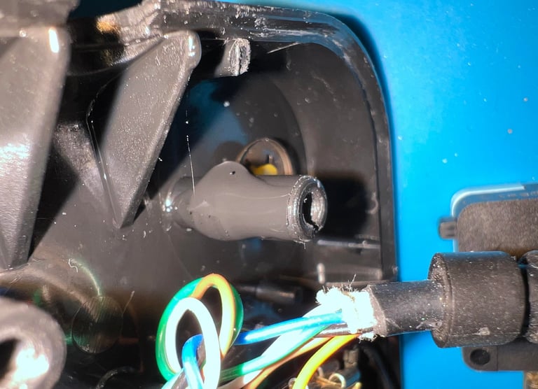
Repairing a broken screw standoff
Ok, repairing is probably not the correct word. But one of the screw standoff is broken or split. To reduce the risk of further damage the standoff is covered with some black isolation tape, and then the tape is coated in superglue. This will not repair the standoff, but hopefully it will not break further.

Interior
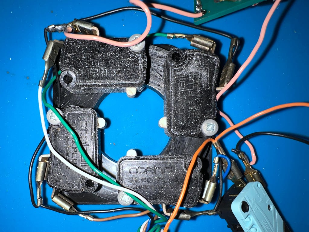
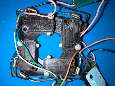
Microswitches
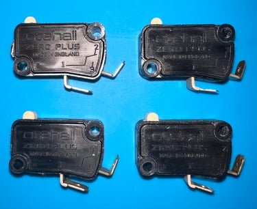
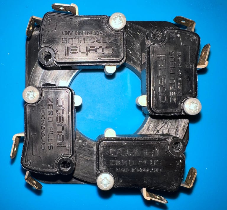
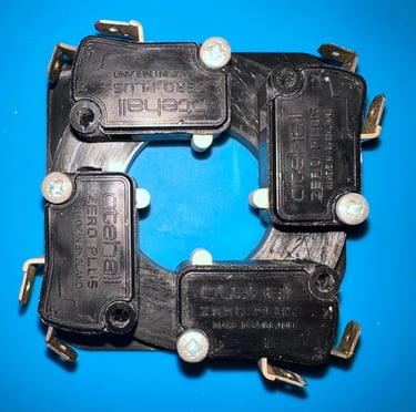
As previously mentioned four of the microswitches, which are mounted on a plastic ring, are covered with some odd shiny looking dust. I have no idea what this is, but I have a hypothesis that this is caused by a chemical reaction in the microswitch plastic cover.
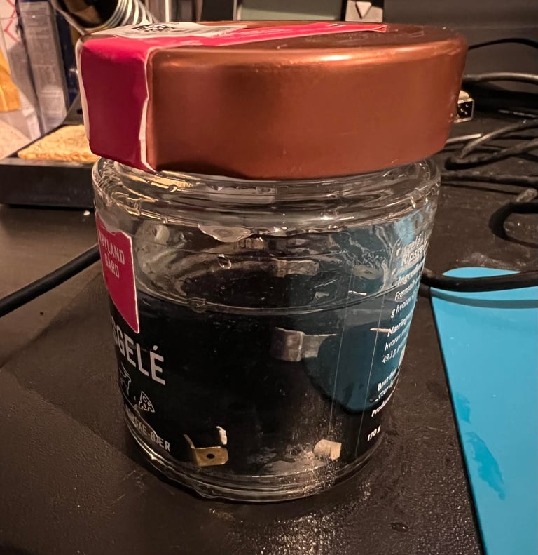
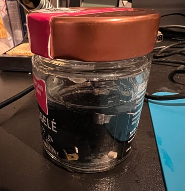
Since my hypothesis is that this dust is caused by a chemical reaction in the plastic, the dust could also be on the inside of the four microswitches. But to avoid any damage to these they are not opened, but each microswitch is placed in a jar of isopropanol for 24 hours. This should remove any inside dirt.
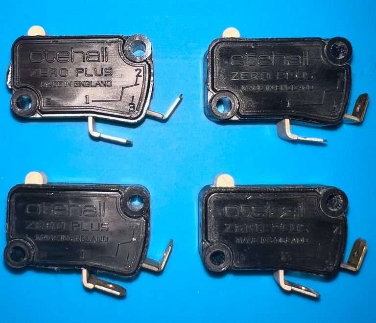
The result after the "isopropanol bath" is very good. All of the odd looking dust is gone, and the microswitches looks as new. As can be seen from the pictures below, these microswitches are Othehall Zero Plus quality switches (made in England).
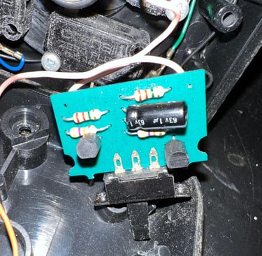
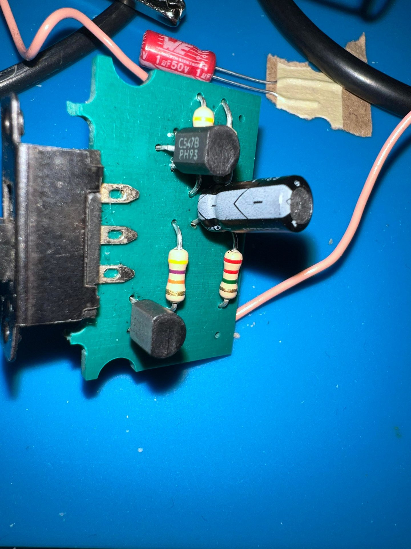
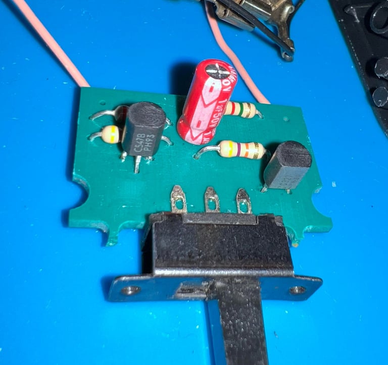
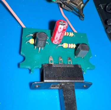
PCB
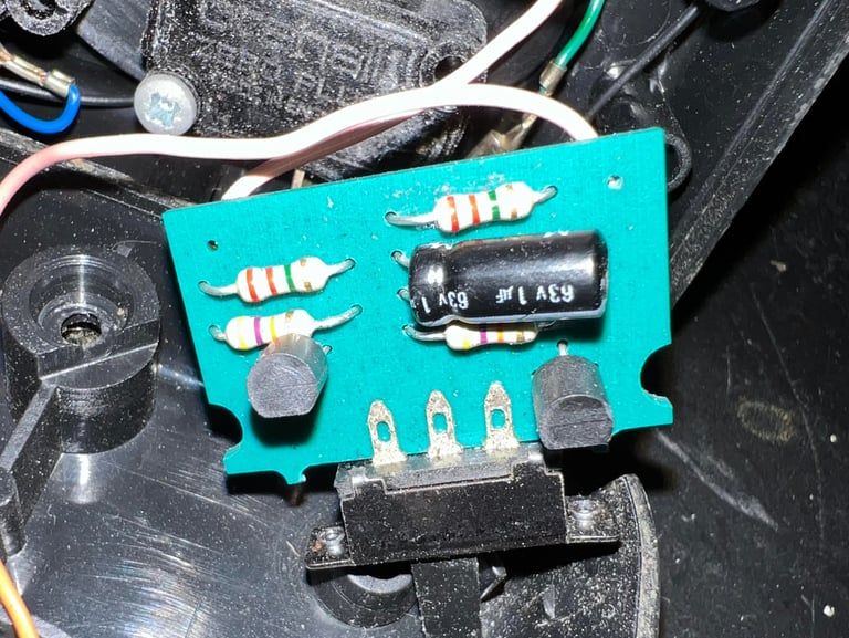
There is a small PCB in the joystick consisting of a couple of transistors (C547B and C327), four resistors and a 1 uF 63V capacitors. The purpose of this circuit is to generate the auto fire pulses. Although not crucial for the operation, the electrolytic capacitor is replaced as a homage to the engineers who made it. As old electrolytic capacitors dry out they loose their capacitance. And as a consequence of this the pulse frequency would likely be different from what the engineers designed it to be.
Therefore the 1uF electrolytic capacitor is replaced with a new red modern capacitor from Wurth. Note that the new capacitor is rated for 50V instead of 63 V, and of course... 50 V is more than enough(!). Pictures below from before and after.

Connectivity
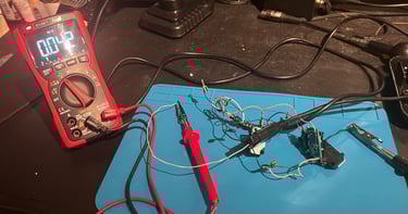
It is not uncommon that one or more of the joystick wires break after intensive use over several years. Checking the continuity from the connector pins to the microswitches both simple and effective. While the multimeter is in continuity mode all wires are checked - also when the wires are wiggled. Below is the schematics of the joystick connector (note: keep in mind to mirror this if you are looking at the front of the connector).
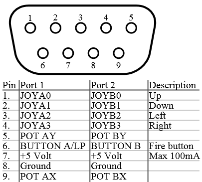

In this Zipstick joystick use six of the nine pins; UP/DOWN/RIGHT/LEFT/FIRE/Ground. Other autofire joysticks, such as this Zipstik as an example, often use the +5V DC, but this is not the case with this one.
All of the six wires seem to be working without any issues. Below is a picture from the testing.

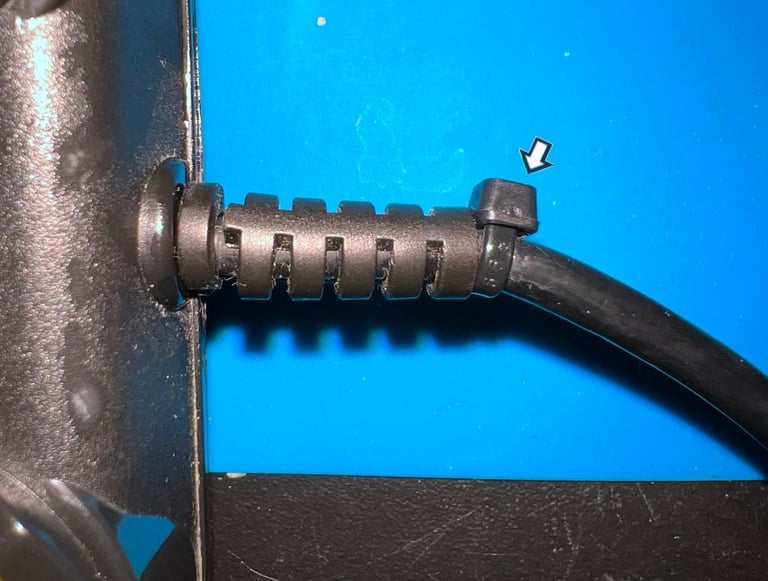
As mentioned in the first chapter the strain relief is partly broken. Luckily, the important part of the strain relief is still intact. A small black cable tie is fastened at the end of the strain relief. This should hold it in place well enough.

Testing... and repair
After re-assembly the joystick is tested. And immediate it is clear that the LEFT direction doesn´t work. Well, that is not completely true. It does work, but when the bottom cover is mounted the LEFT microswitch does not close. And this is not due to any stuck wire, or something else stuck for that matter. It is because the small plastic knob which enables the switch needs to be completely pushed in on this very microswitch.
So the microswitch needs to be repaired. The switch is carefully opened by using a thin small flat screwdriver to pry it open.

The curved metal plate is carefully twisted every so slightly. This makes the tension a bit stronger which results in a more "quick" response when the white plastic plunger is pressed. In the picture below two arrows indicate where the small twisting is performed.
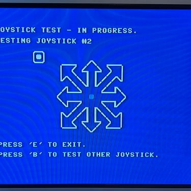
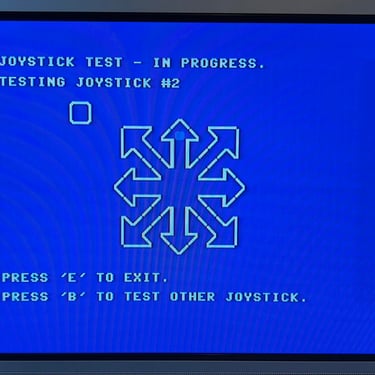
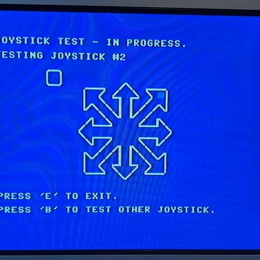
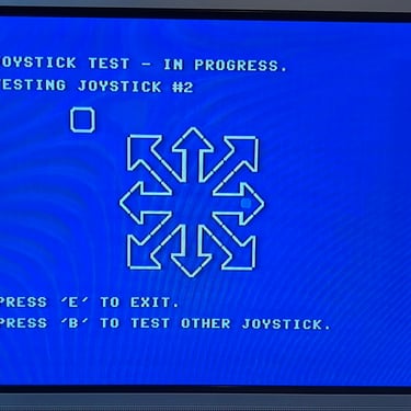
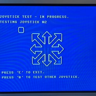
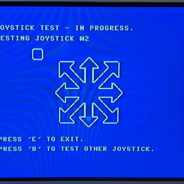
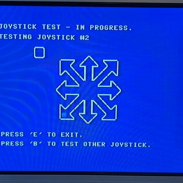
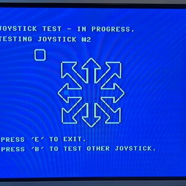
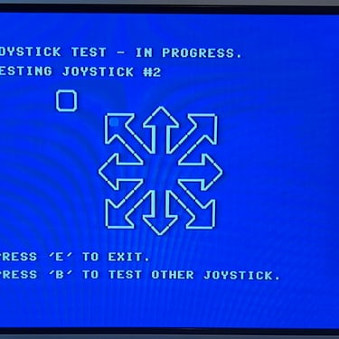
Testing
To verify that the joystick work as it should I check it with the 64 Doctor software. Result is that all directions and fire buttons works fine works as expected. All tests pass.
Final result
"A picture worth a thousand words"
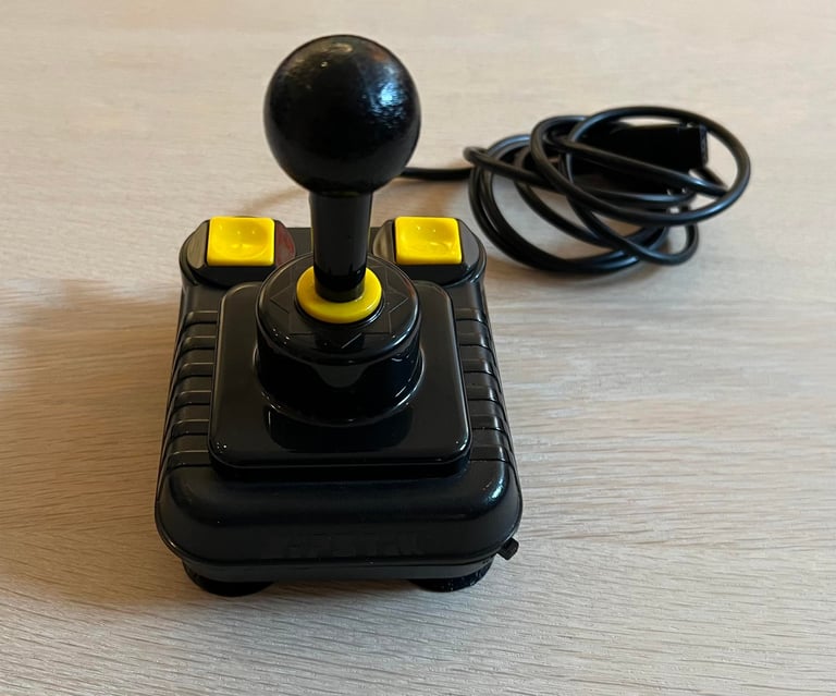
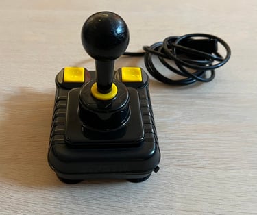
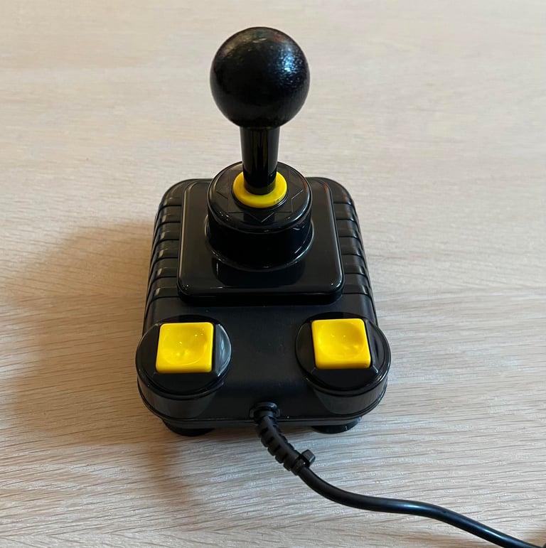
Below is a collection of the final result from the refurbishment of this Zipstik joystick. Hope you like it! Click to enlarge!


Banner picture credits: unknown