
Zipstik
Starting point
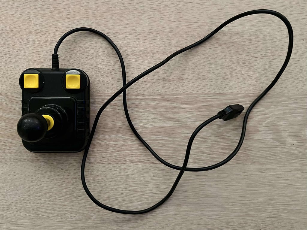
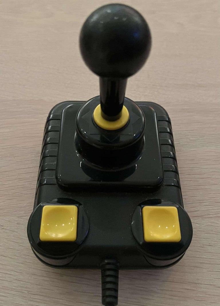
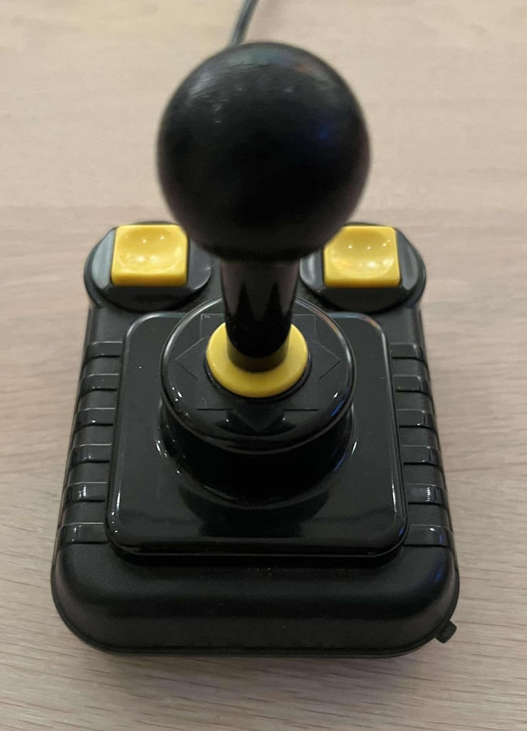
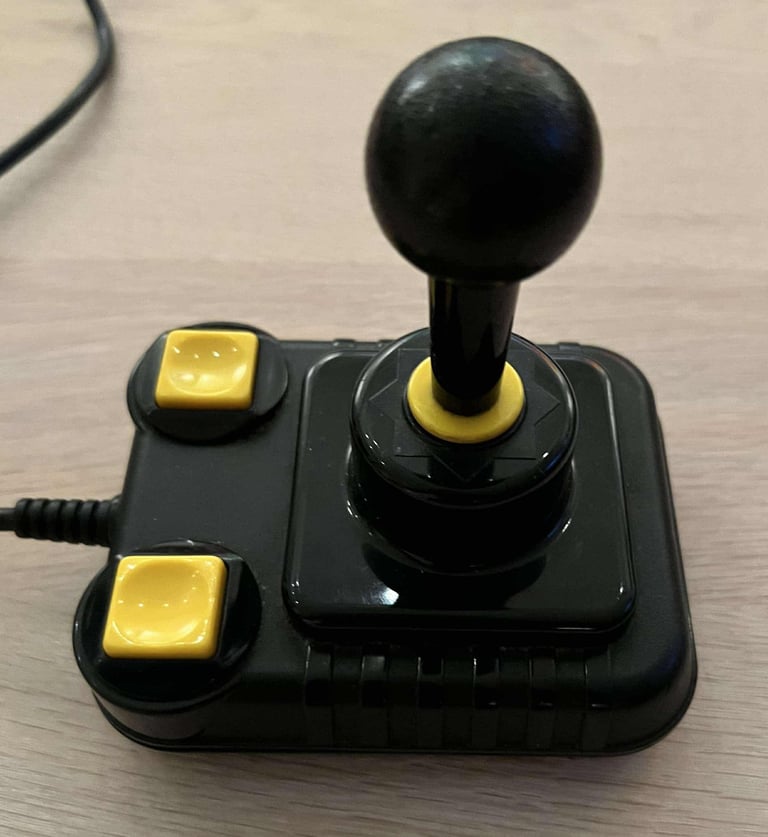
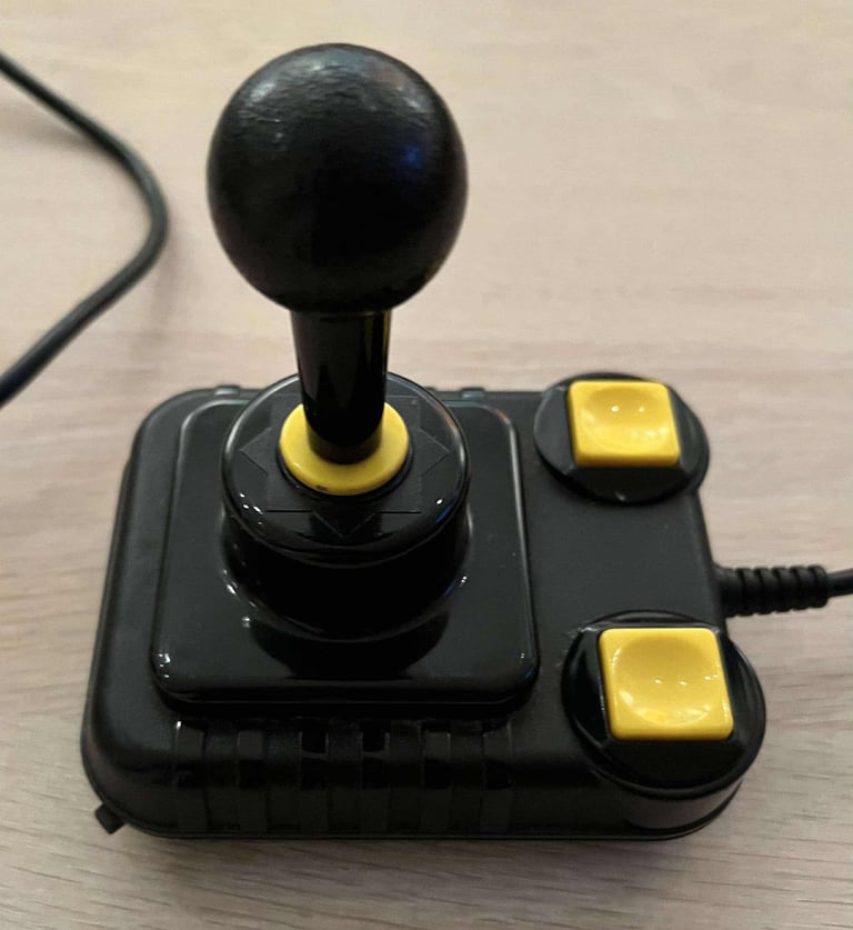
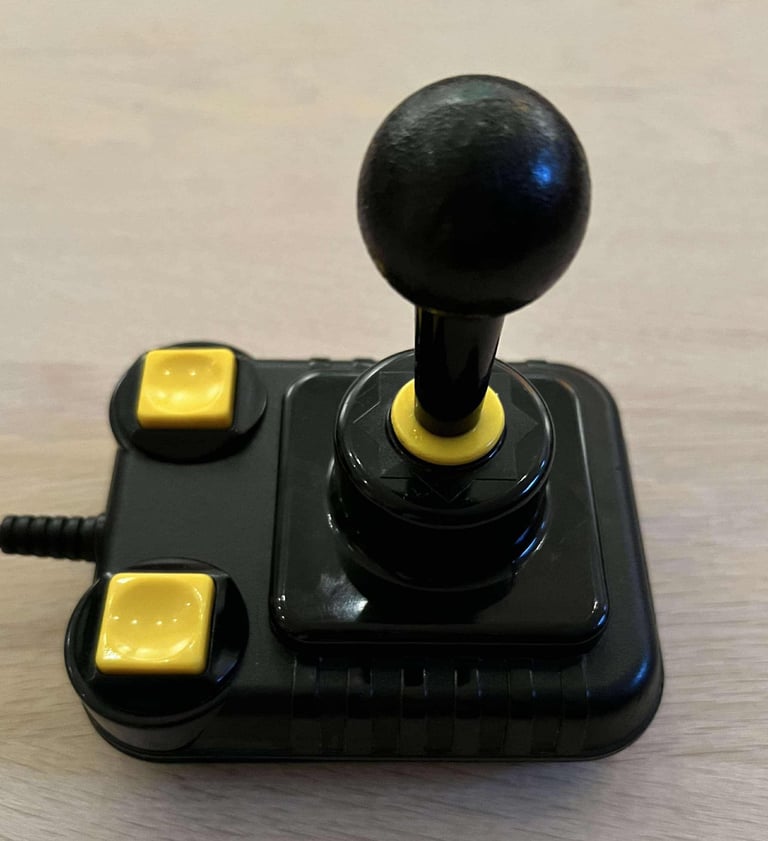
"Don´t judge a book by its cover" - this joystick is worse than it looks unfortunately. Yes, the outside looks very nice, but there are some serious faults:
The right FIRE button feels very wrong. When pressed down the expected "click" from the microswitch below is not always heard. Or, when it is heard it is like it is delayed?
The AUTOFIRE switch have seen better days. It feels both stuck and in a somewhat wrong position.
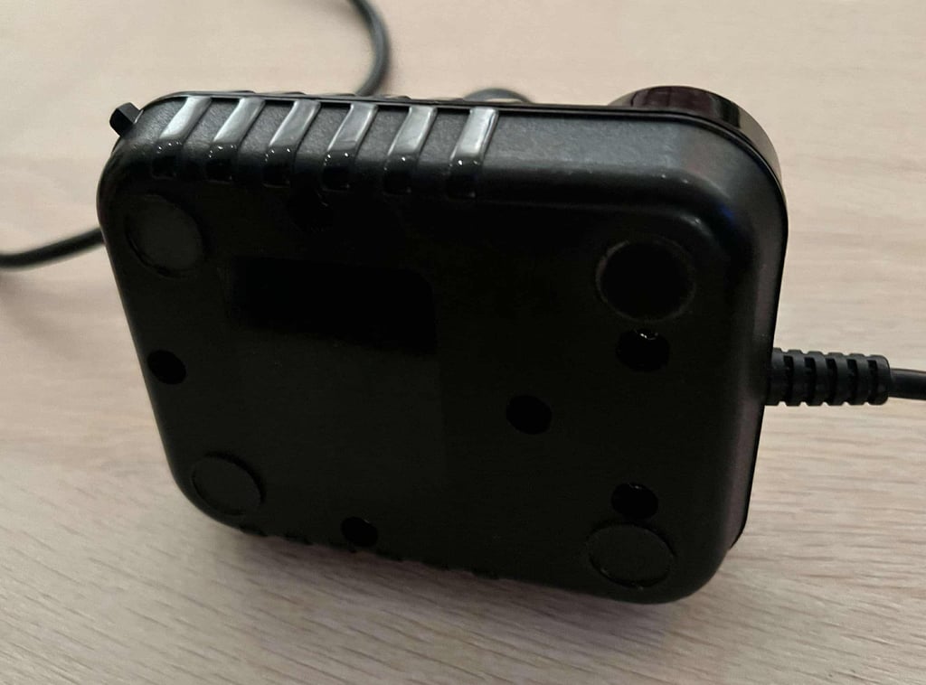
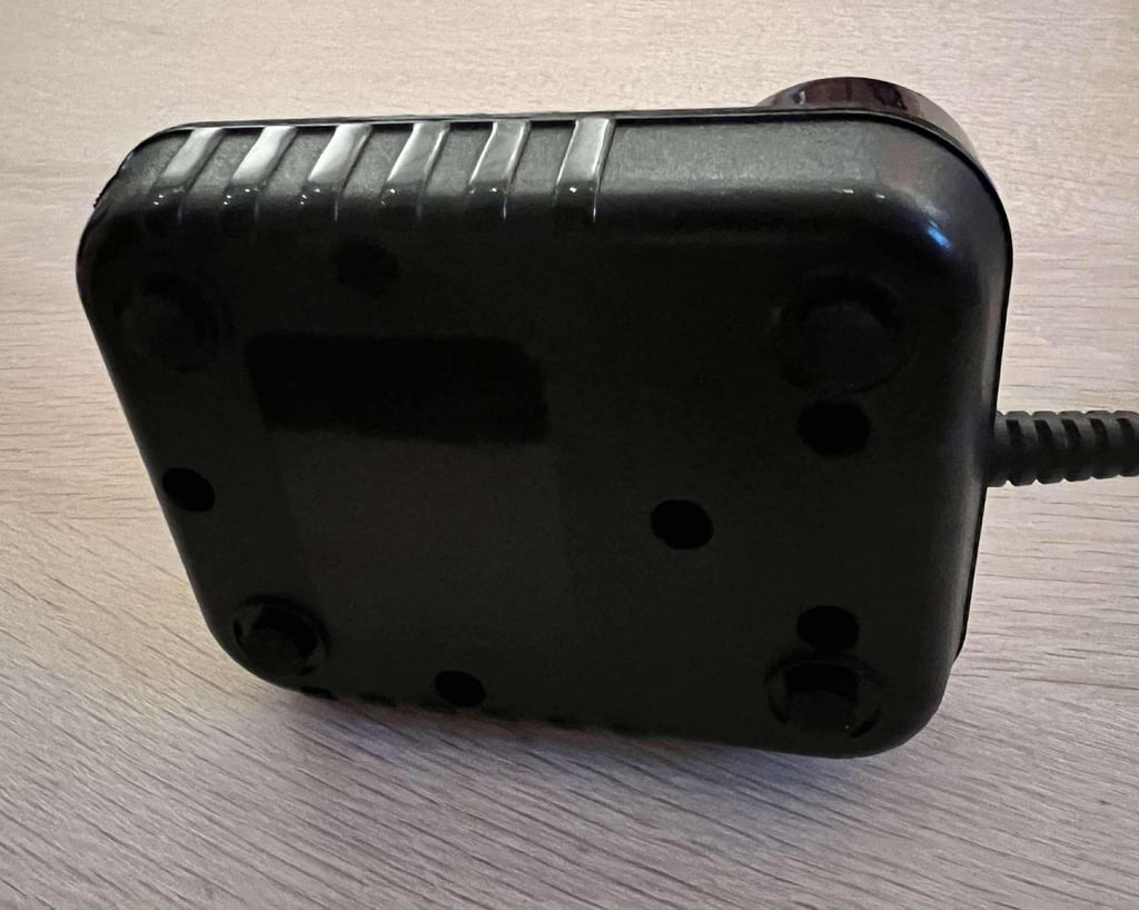
The bottom cover is not properly attached even if all five screws are present. This could be due to broken screw stand-offs (?), and could also be partly the cause why the right FIRE button is not working as it should. There are no rubber feet at the bottom cover. Although, I have seen this on other Zipstik joysticks, but I still think that there were four thin rubber feet originally.
There are some signs of use on the top- and bottom cover, but not too serious.






Refurbishment plan
To refurbish this joystick the plan is to do this trough the following steps:
- Clean, and remove stains from, chassis and all parts (and repair if required)
- Lubricate moving parts
- Clean and check the microswitches (and repair if required)
- Clean and check autofire PCB (and repair if required)
- Check connectivity (and repair if required)
- Verify joystick operation by testing
Disassembly
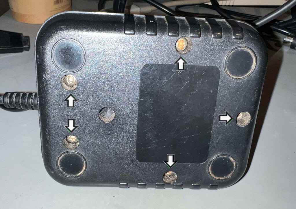
Disassembling the Zipstik starts with removing the five screws (Pozidrive 3.5 x 13.5 mm) at the bottom.

With the screws out of the way the top is lifted from the bottom cover. It is very nice to see that the inside looks very good - very little grease and dust, and I can not see any immediate faults.
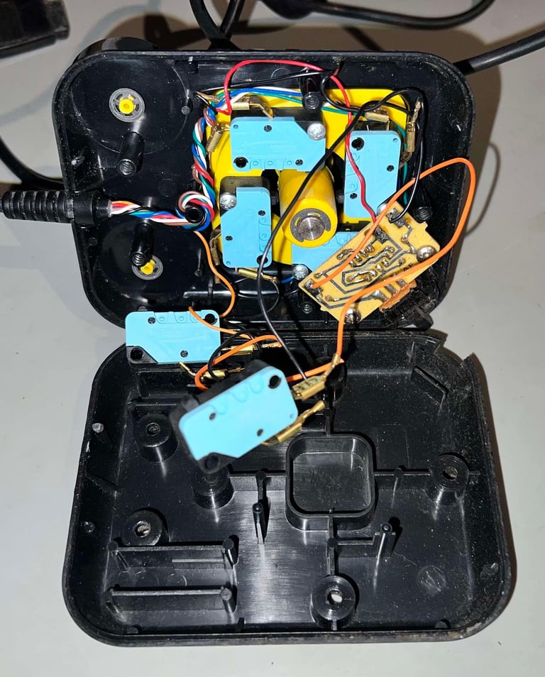

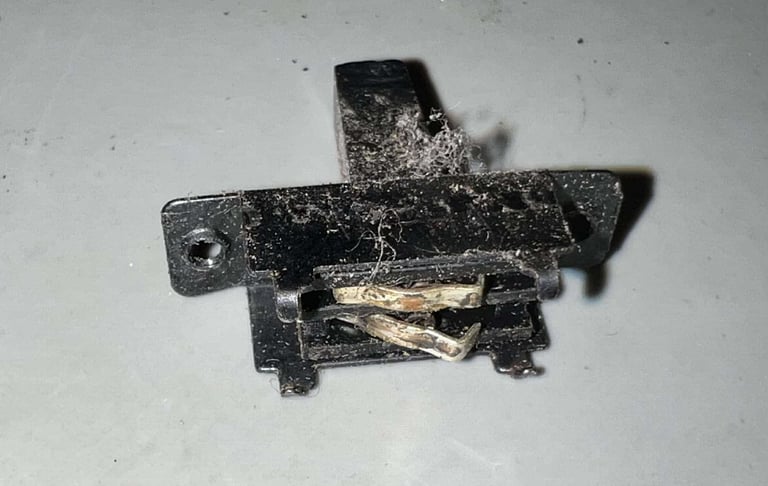
No visible damage? Not so fast... With closer inspection I see that the AUTOFIRE switch is barely holding fast to small PCB. Even with the small metal grips the switch itself is more or less completely loose. This switch is probably beyond repair (or to be more precise: it is possible to re-assemble it, but this kind of switch needs to be able to handle normal usage. And since the switch is worn out it is likely that it will not handle normal usage without breaking.)
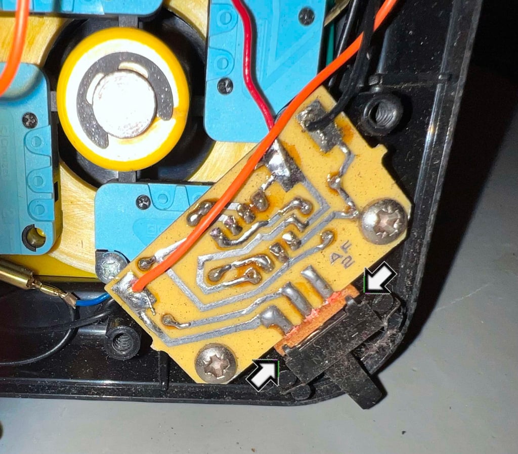

Both of the two screws (pozidrive 3.5 x 13.5 mm) are removed from the AUTOFIRE PCB. When the PCB is removed the switch literally just disintegrates... no surprise...


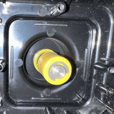
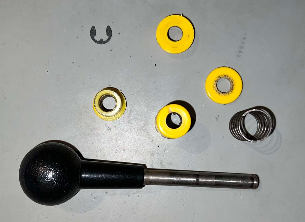
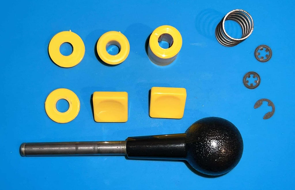
Next action is to disassemble the joystick shaft. First the E-clip is removed from the bottom of the shaft with a flat thin screwdriver. With this out of the way the plastic parts, and the spring, is removed one by one. In the gallery below you can see the order which the parts were removed.
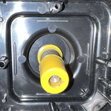
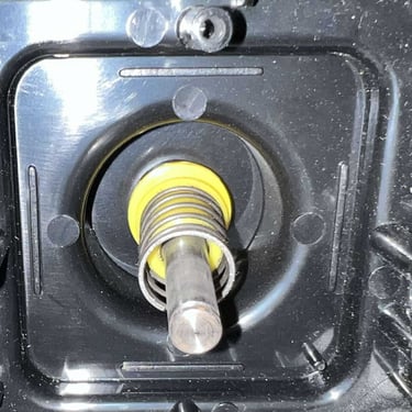
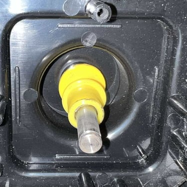
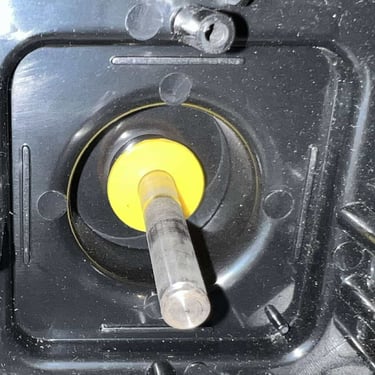
Below is a picture of the plastic parts, and spring, from the disassembled joystick shaft.

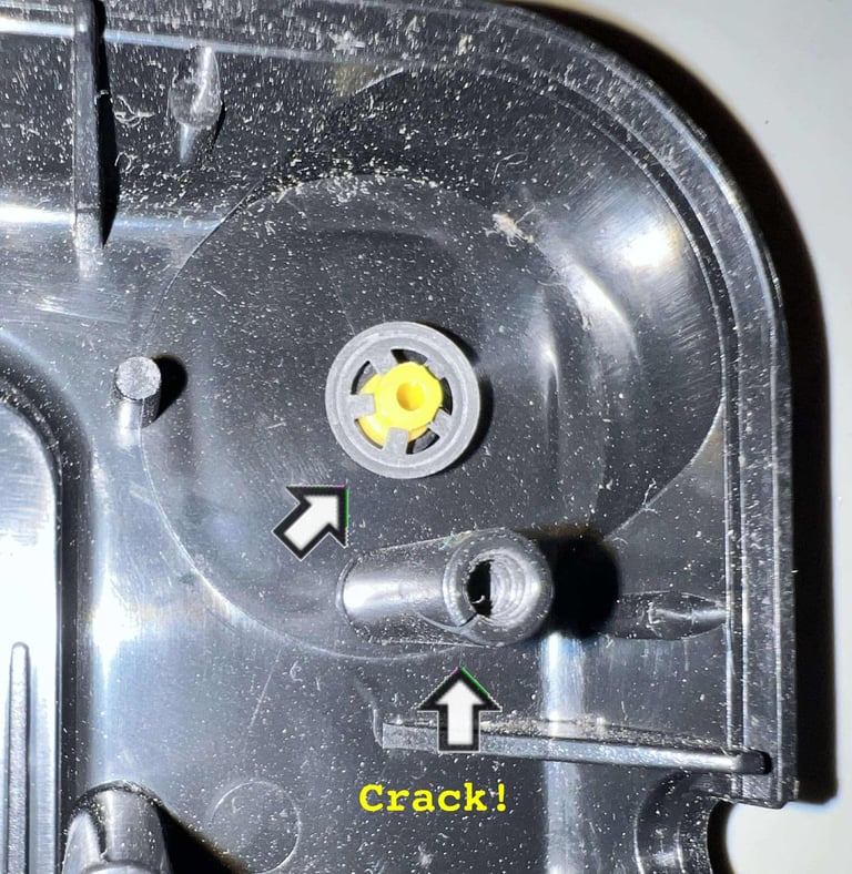
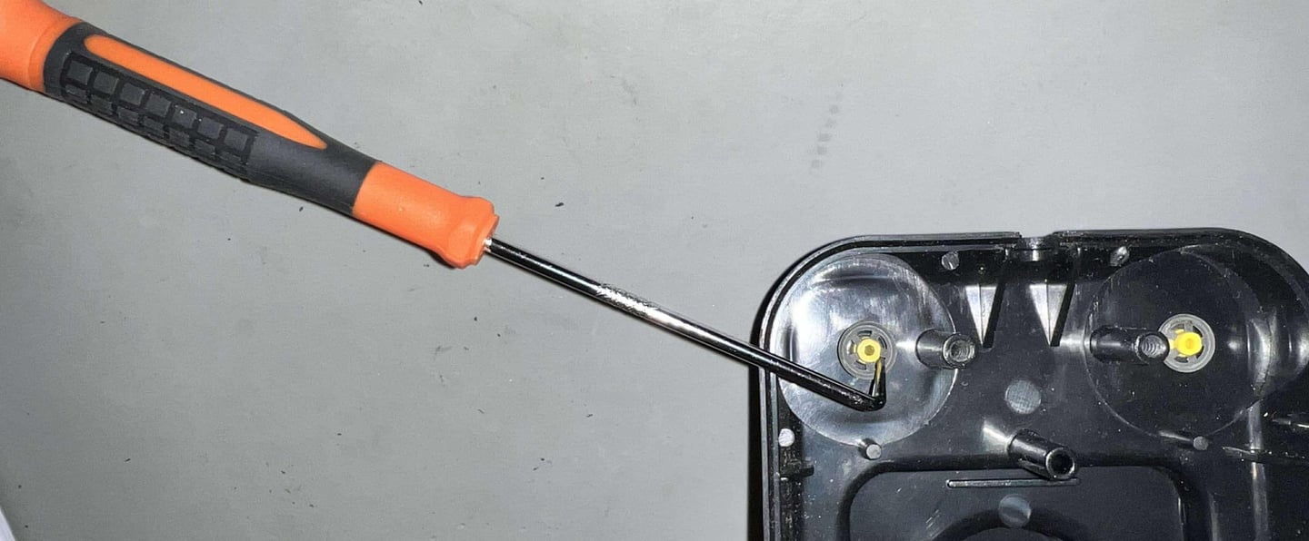
Disassembling the FIRE buttons is not complicated, but it is wise to be careful not do damage the parts. From the bottom side of the FIRE button the metal clip is removed using a thin pick tool. With the metal clip out of the way the FIRE button is simply lifted away from the bottom cover.
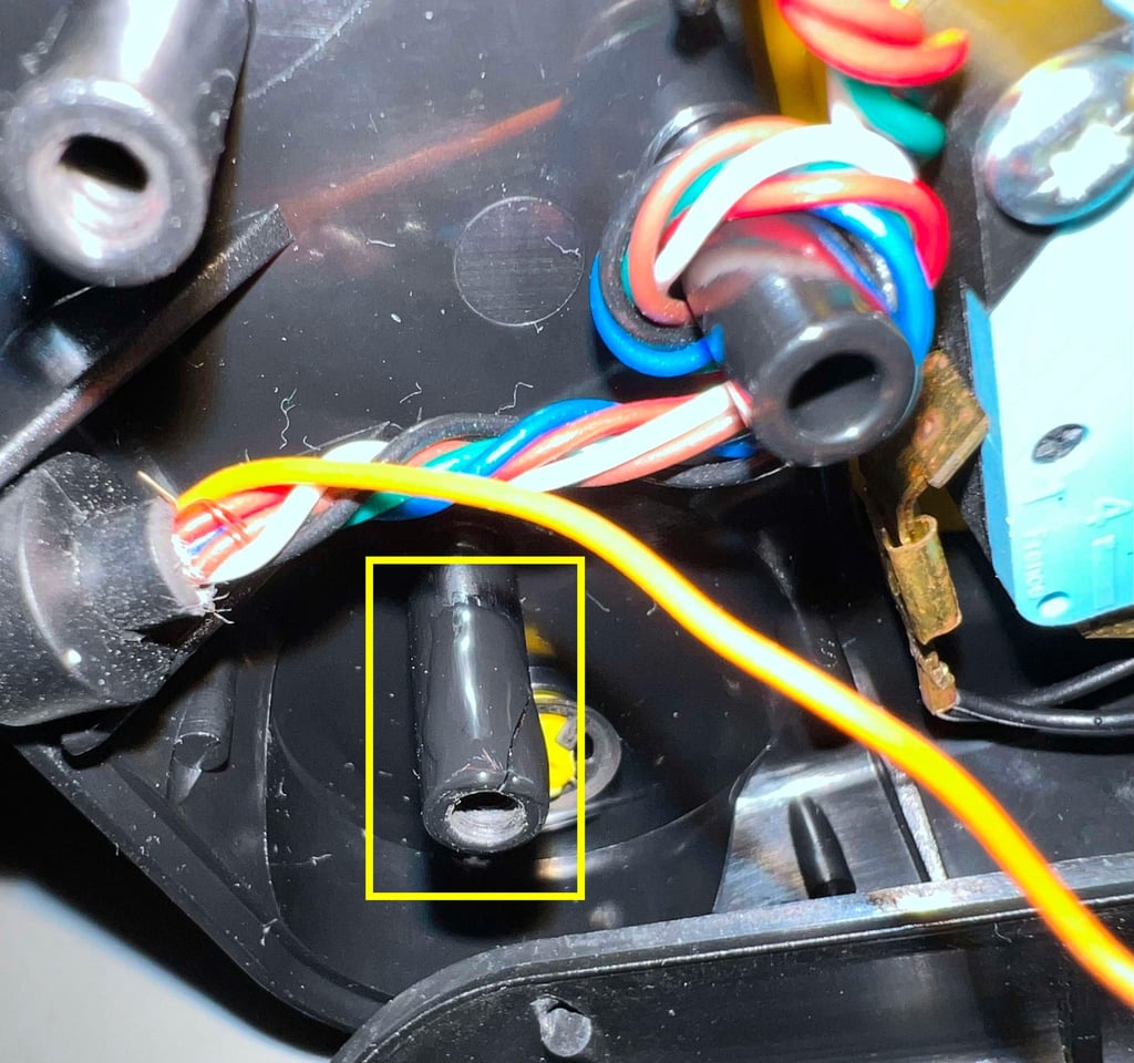
Now I notice something else also. Remember that the right FIRE button was not always responsive? I see that there is a small crack in the standoff for the right screw - just next to the right FIRE button. This could be part of the problem. It is not easy to fix these broken standoffs, but I will try to add some superglue around it to prevent it from breaking further.


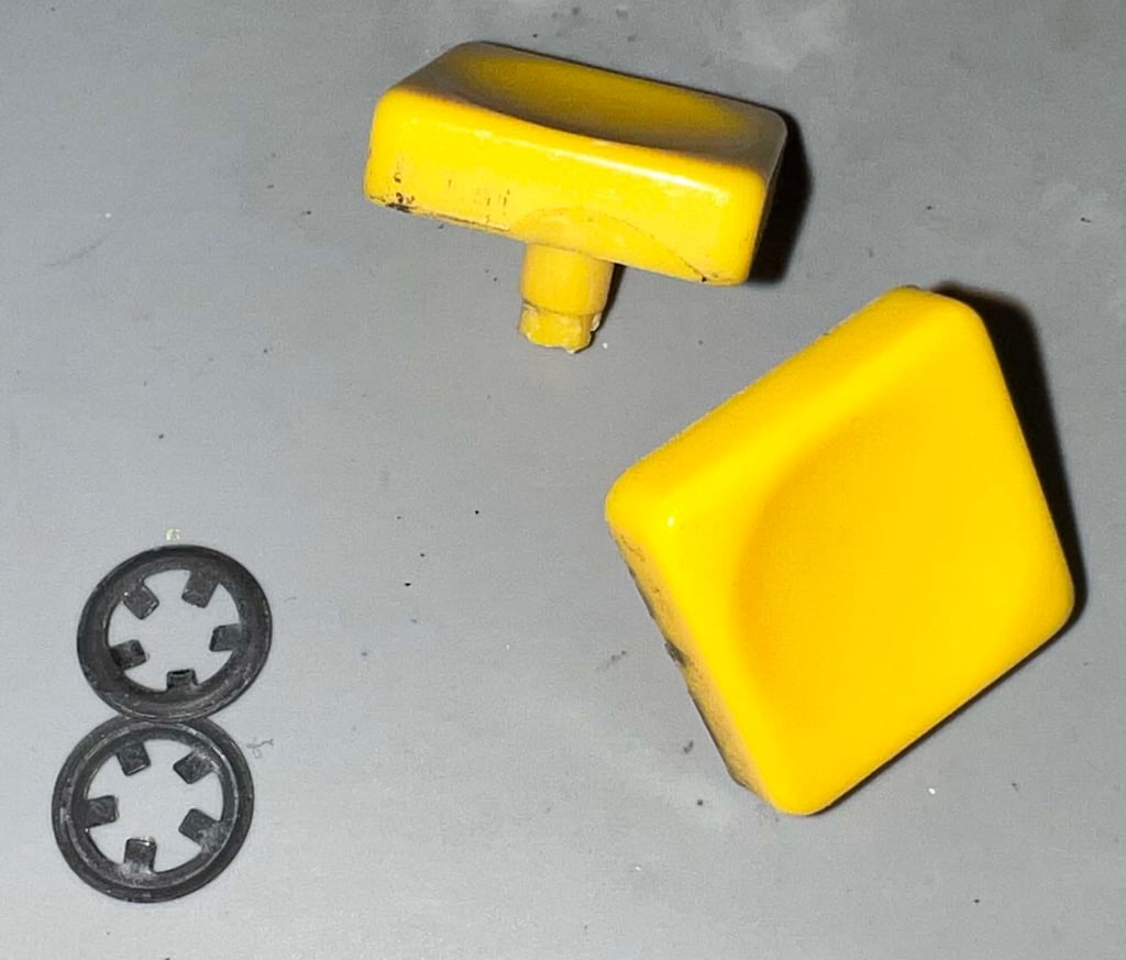
Below is a picture of the disassembled FIRE buttons.

Exterior casing and plastic parts
Cleaning the plastic parts
It all starts with a bath! All parts are soaked in mild soap water for about 24 hours. After this long period most of the grease is dissolved without mechanical rubbing. In addition a little bit of glass cleaning spray is also added to the water.
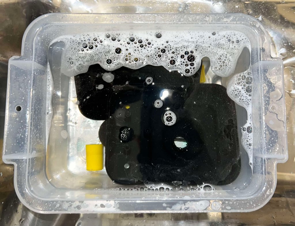

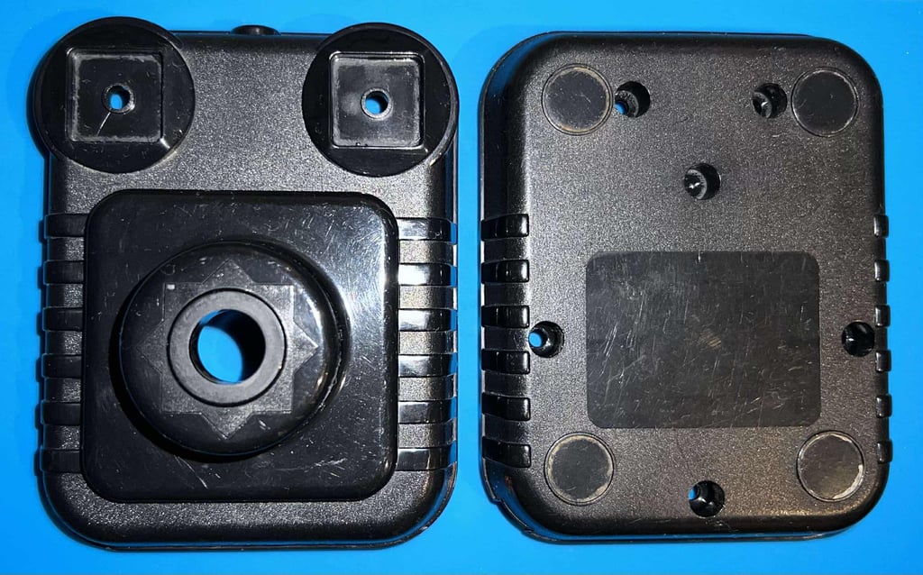
After cleaning the parts look way better. The signs of use are now quite apparent, but the parts are now very good looking.


Lubrication
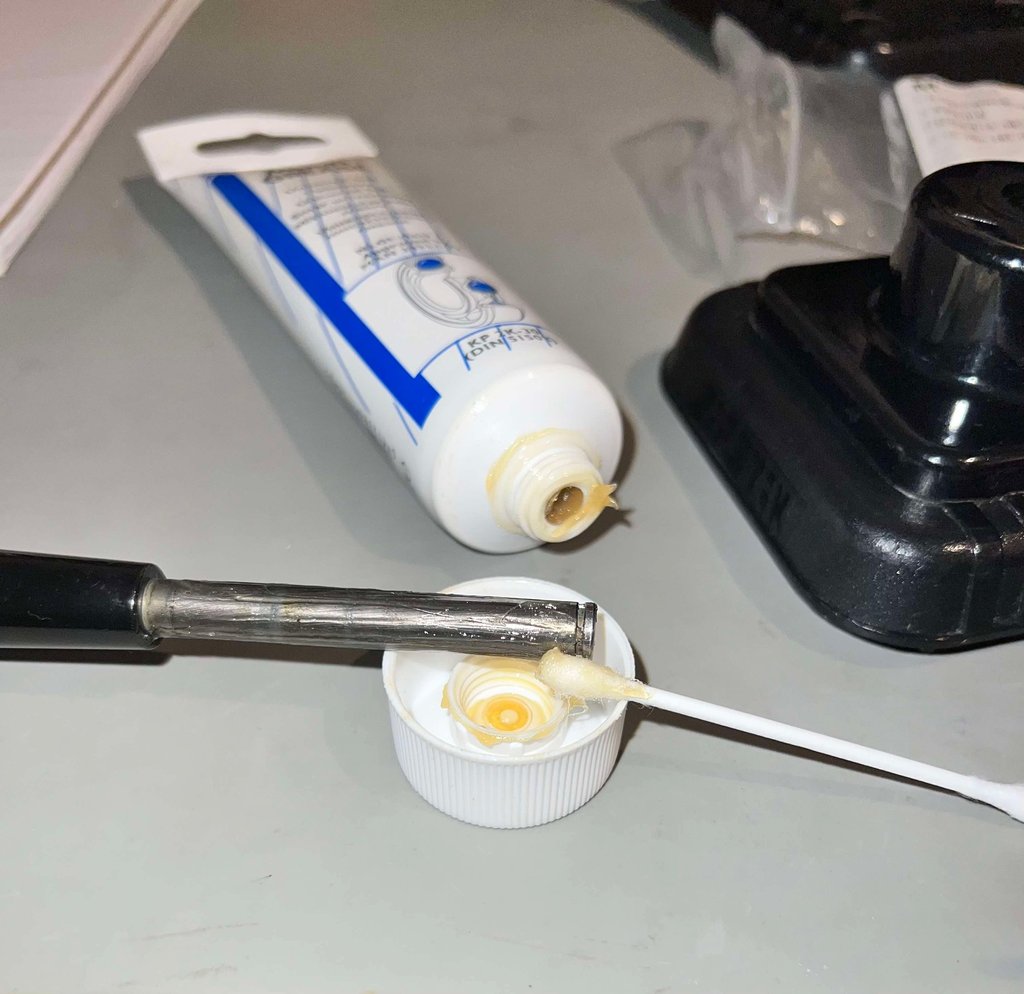
Although not strictly necessary, I think it is good practice to lubricate the moving parts. By adding some small amount of multi purpose grease on the metal shaft, and the interior of the plastic parts, the risk of squeaky noises and friction is reduced. The FIRE buttons are also lubricated slightly with some sewing machine oil at the center plastic shaft of the buttons.

Repairing the standoff
The standoff, holding the screw for the right hand side FIRE button, is slightly cracked. Is it not possible to repair this 100 %, but by covering the outside with super glue I think it should help preventing further cracking.

Replacing (?) the rubber feet
Although not 100 % sure, I think that all of the four rubber feet are missing.
Electronics and microswitches
Disassembly
Disassembling the interior is quite straightforward:
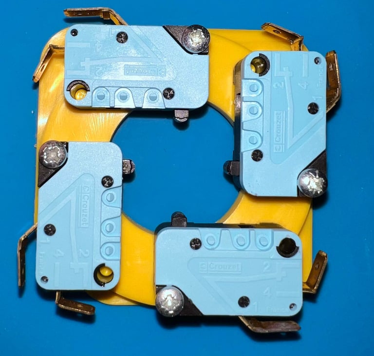
The four directional microswitches are mounted on the plastic bracket with 3 x 16 mm pozidrive screws which are removed
The cable shoes of all six microswitches are pulled off the switches
The three wires GND, +5VDC and FIRE are desoldered from the AUTOFIRE PCB
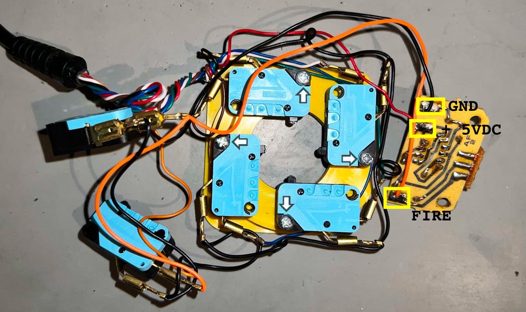

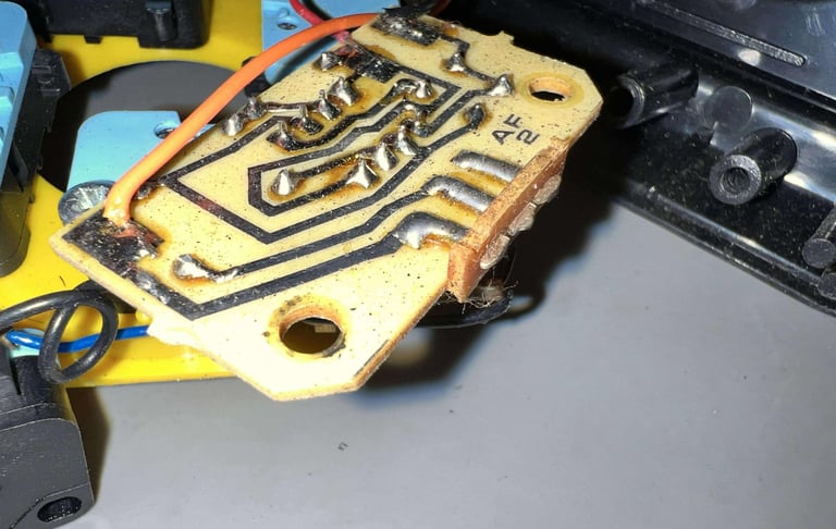
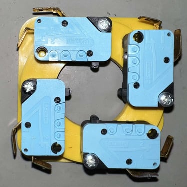
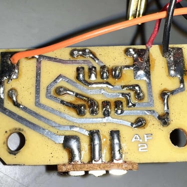
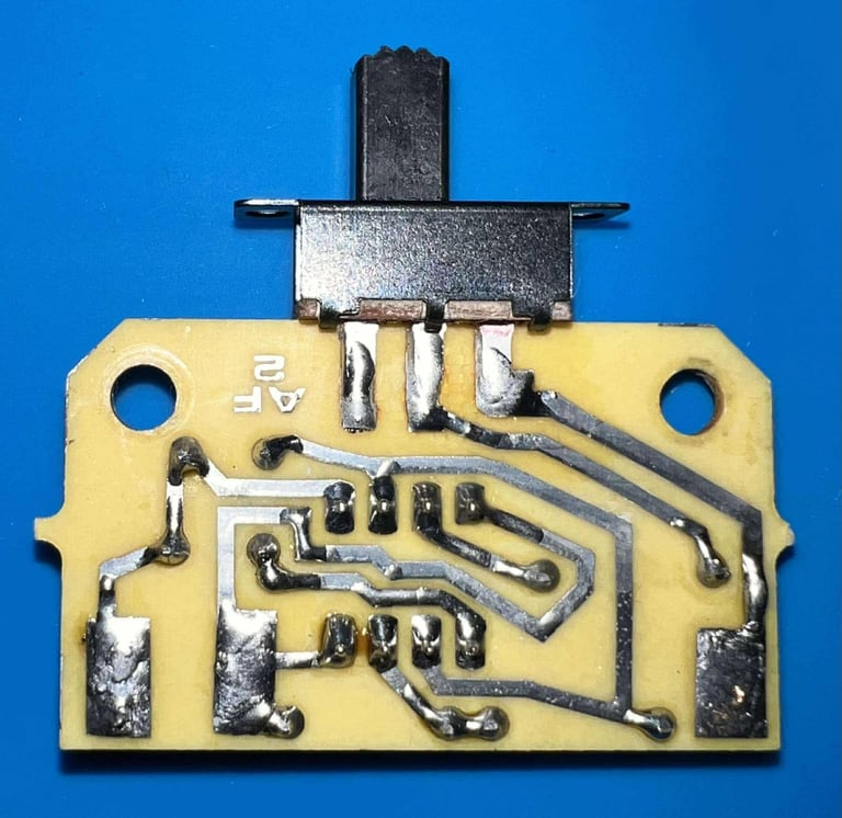
Below is a picture gallery from the disassembly. As can be seen from the pictures below the version of the AUTOFIRE PCB is "AF2" (a qualified guess is that this means AutoFire2 (?)").
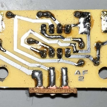
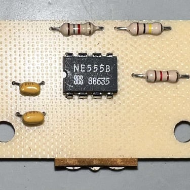
Replacing the AUTOFIRE switch
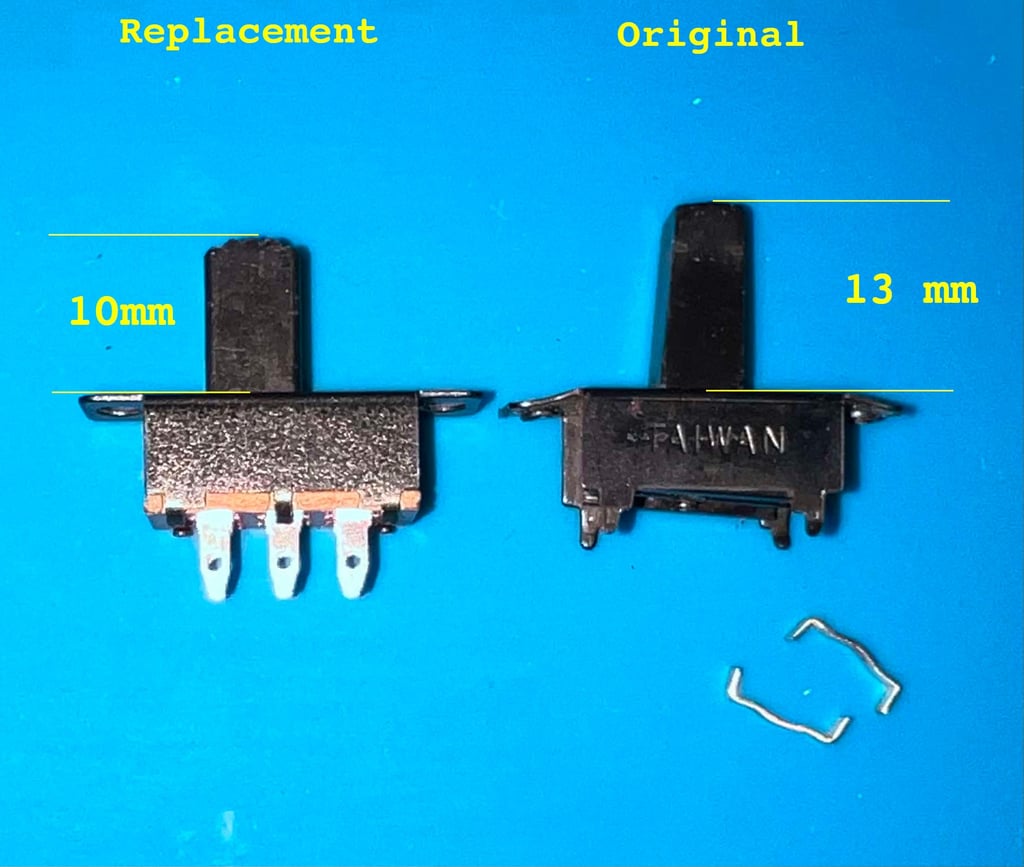
The original AUTOFIRE switch is beyond repair. Part of the "PCB" which functions as the base of the switch is simply disintegrated. It is not easy to find an identical replacement, but a close replacement is found at DigiKey (Part. No: 2449-MS2202L9B-ND).
The main difference between this replacement switch and the original is the length of the stem. The original stem is 13 mm, but the replace stem is only 10 mm. See picture below.

Cleaning the electronics
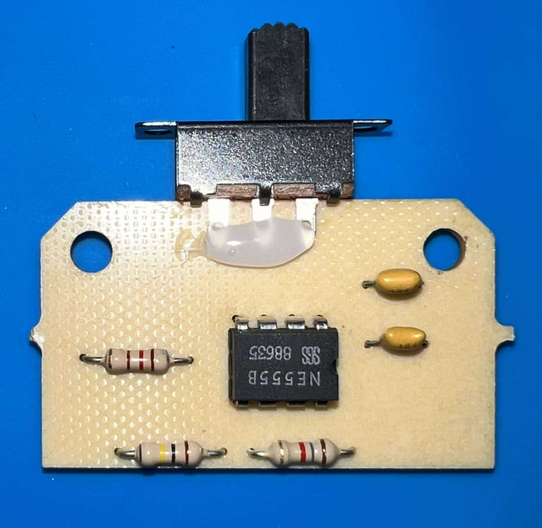
The AUTOFIRE PCB, with the new switch installed, is properly cleaned with isopropanol. Notice that a small amount of glue is placed on the topside of the PCB to strengthen the mounting of the switch. Since this is a 2-pole switch half of the switch is not used with this PCB.


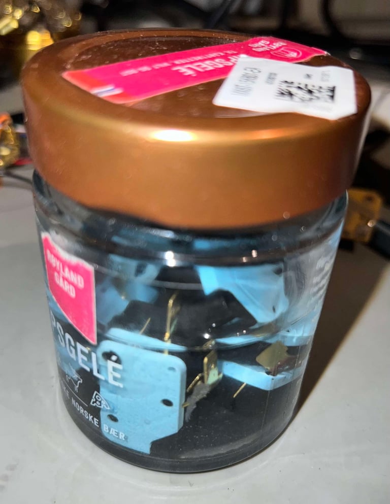
All of the six microswitches are placed in a jar filled with isopropanol for about 24 hours. This is probably quite tough for the plastic, but I think its ok - and it should dissolve most of the internal grease.

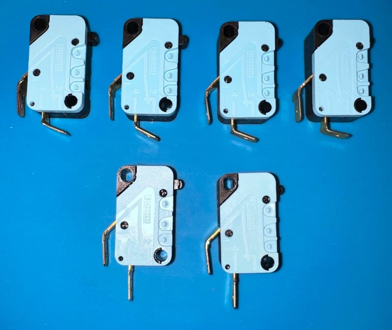
In this joystick the microswitches are all made from Crouzet. By that I mean that both the microswitches used for the DIRECTION and FIRE functions are of the same brand. Other versions of the Zipstik use different brands for these functions.


Electrical continuity testing
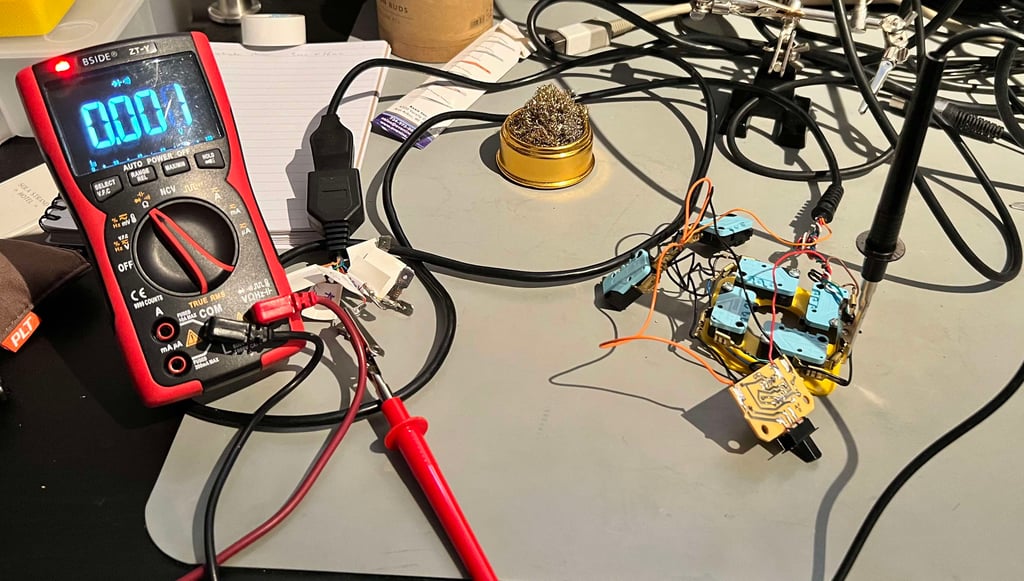
Before the joystick is re-assembled the connector, cable and all microswitches are tested for electrical continuity. I find this a good practice as I can "wobble" the cable while multimeter is in diode-mode (beep mode) - looking for any broken wire or connector.

Modifying the AUTOFIRE function
The original way(*) the AUTOFIRE function is working on this Zipstik is as follows:
With the AUTOFIRE turned OFF the FIRE button functions as normal. Pressing the FIRE button triggers the fire function.
With the AUTOFIRE turned ON the automatic firing start immediately. Pressing the FIRE buttons triggers the fire functions.
(*) Unless a previous owner has modified this AUTOFIRE this is the way it was designed.
But the way I think it should work is as follows:
With the AUTOFIRE turned OFF the FIRE button functions as normal. Pressing the FIRE button triggers the fire function.
With the AUTOFIRE turned ON the automatic firing DOES NOT start immediately. Pressing the FIRE buttons triggers the automatic firing.
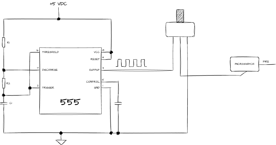
And since the new AUTOFIRE switch is a 2-pole switch where (currently) the 2nd pole is not used doing a small modification should be possible to get the "better" autofire function. To do this the idea is this:
Instead of feeding the GND connector directly to the "bottom" of the FIRE microswitches, the GND is routed to the microswitch via the 2nd pole AUTOFIRE switch (the one currently not used).
The 555-timer circuit producing the pulse train is originally routed directly to the FIRE wire. Instead, this wire is cut and routed to the "bottom" of the microswitch where the GND is normally connected.
The remaining 555-timer circuit is kept as it is - only the GND wire and the output of the 555 timer (pin #3) is routed back to the 2nd pole AUTOFIRE switch.
The schematics of the modified circuit is shown below.

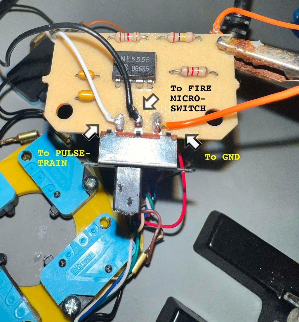
Below is a picture showing how the wiring is done: ground is connected to the leftmost pin, pulse train is connected to the rightmost pin and the "bottom" input on the microswitch is connected to the middle pin.

Testing
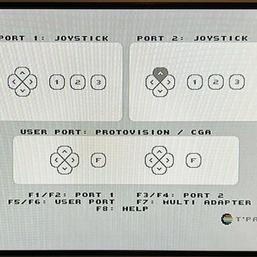
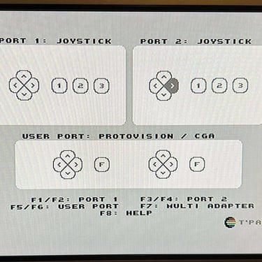
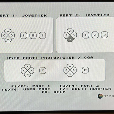
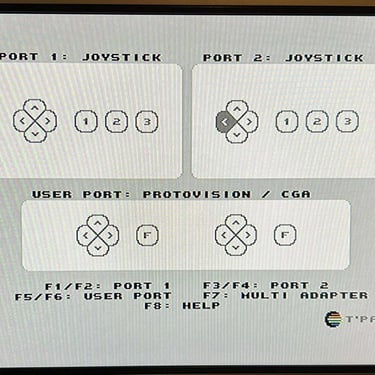
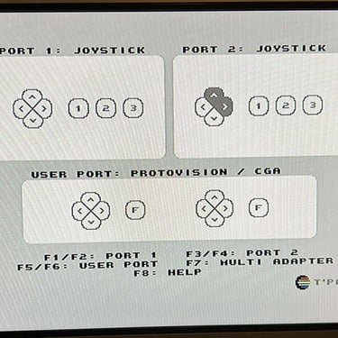
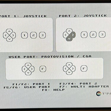
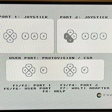
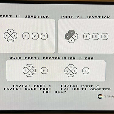
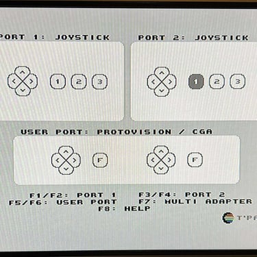
To verify that the joystick work as it should I check it with the Joyride software. Result is that all directions and fire buttons works fine works as expected. All tests pass.
Final result
"A picture worth a thousand words"
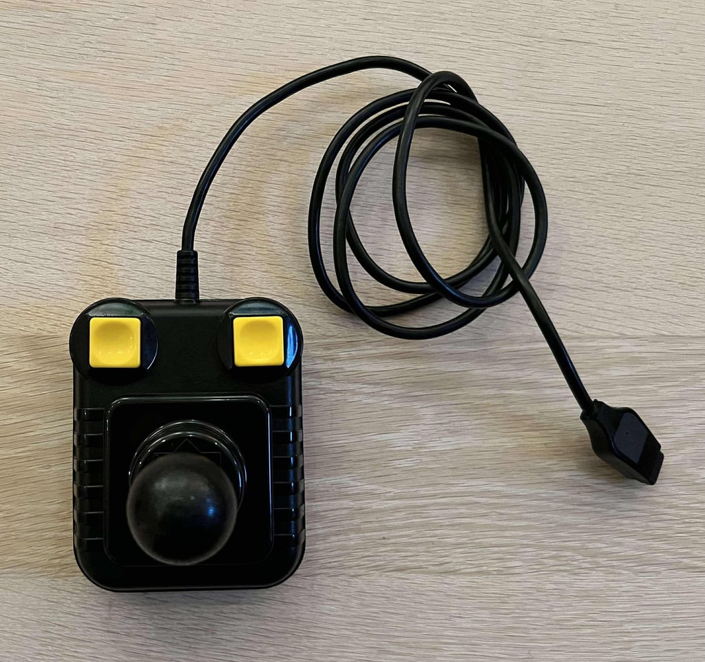
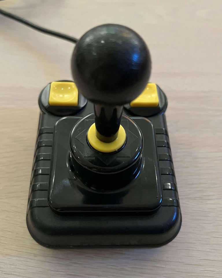
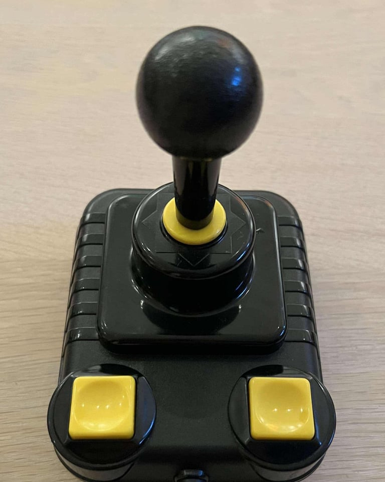
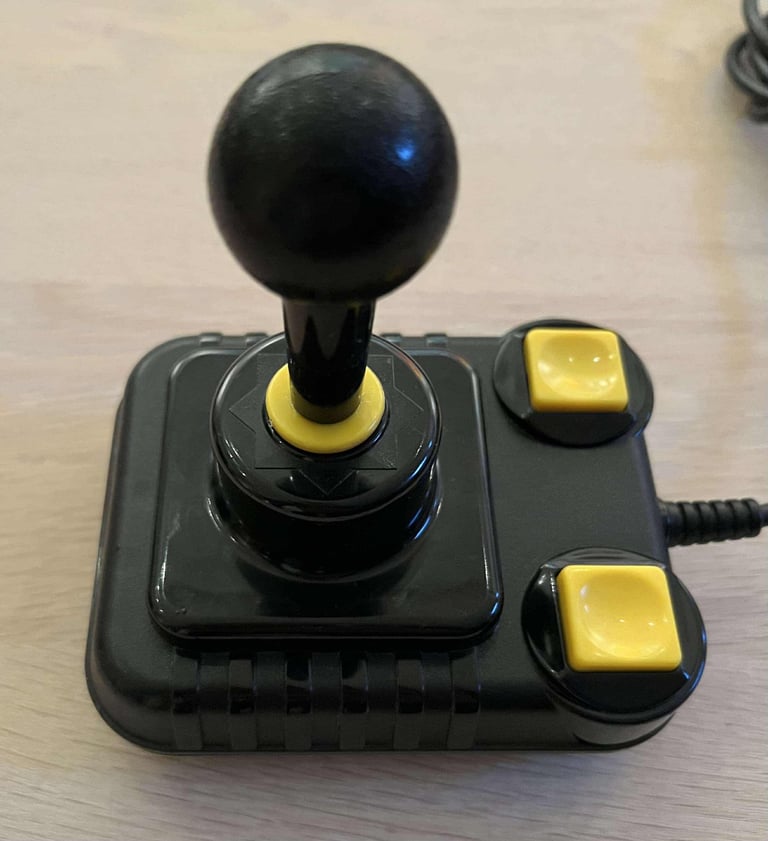
Below is a collection of the final result from the refurbishment of this Zipstik joystick. Hope you like it! Click to enlarge!






Banner picture credits: unknown
