
Zipstik
Starting point
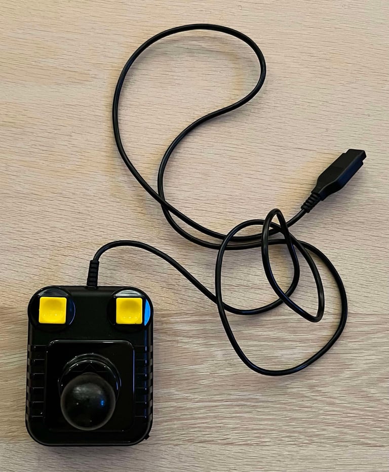
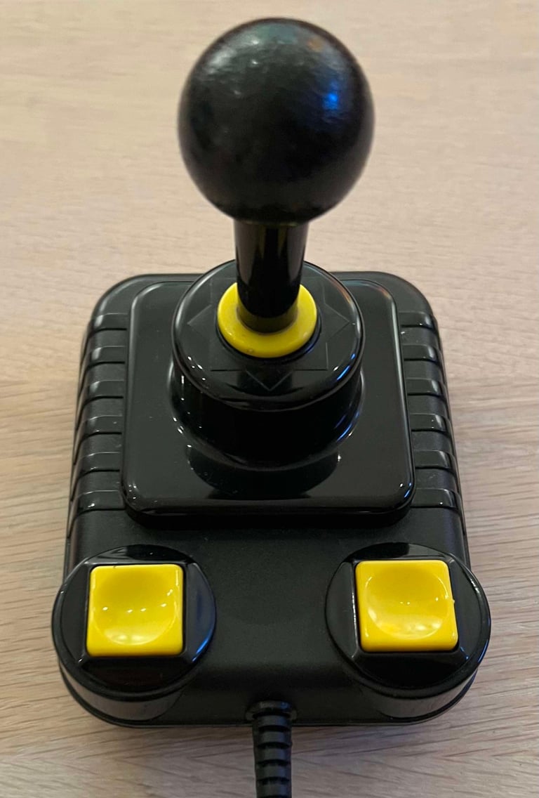
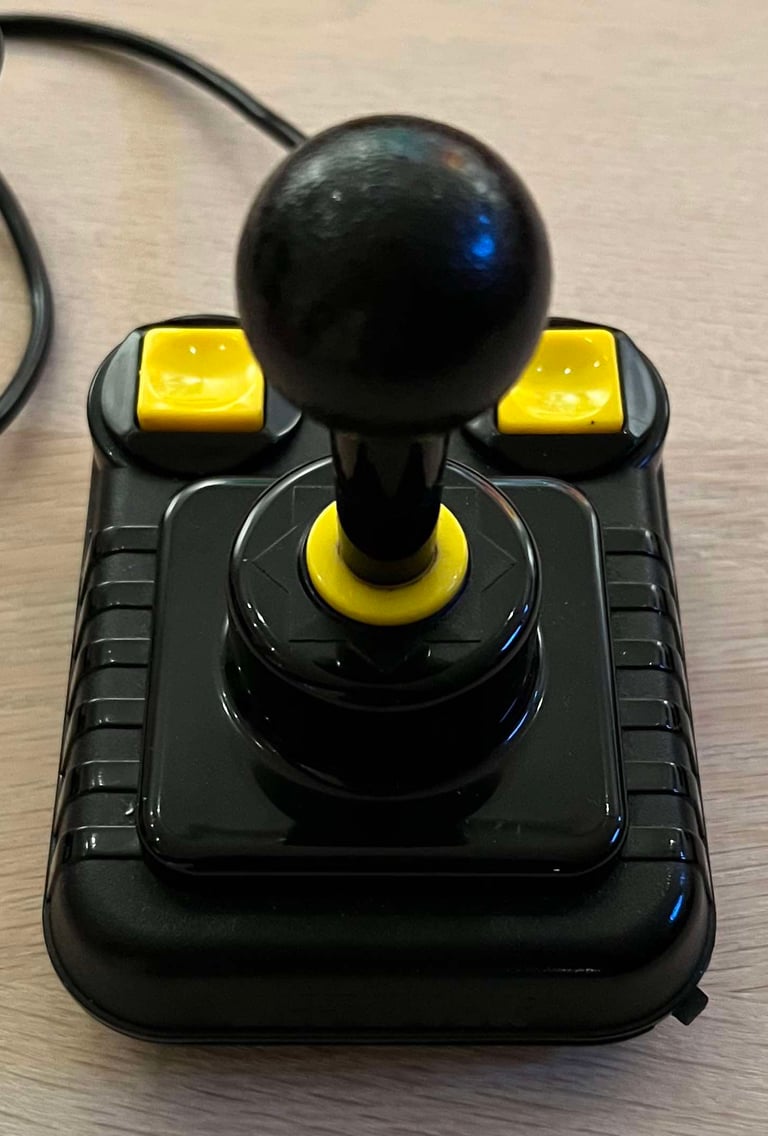
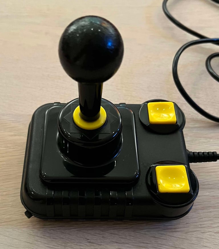
From the outside this Zipstik looks in very good condition. But, we´ll have a closer look at it. Both this Zipstik, and one just recently refurbished, were reported to be a bit "flaky" from time to time.
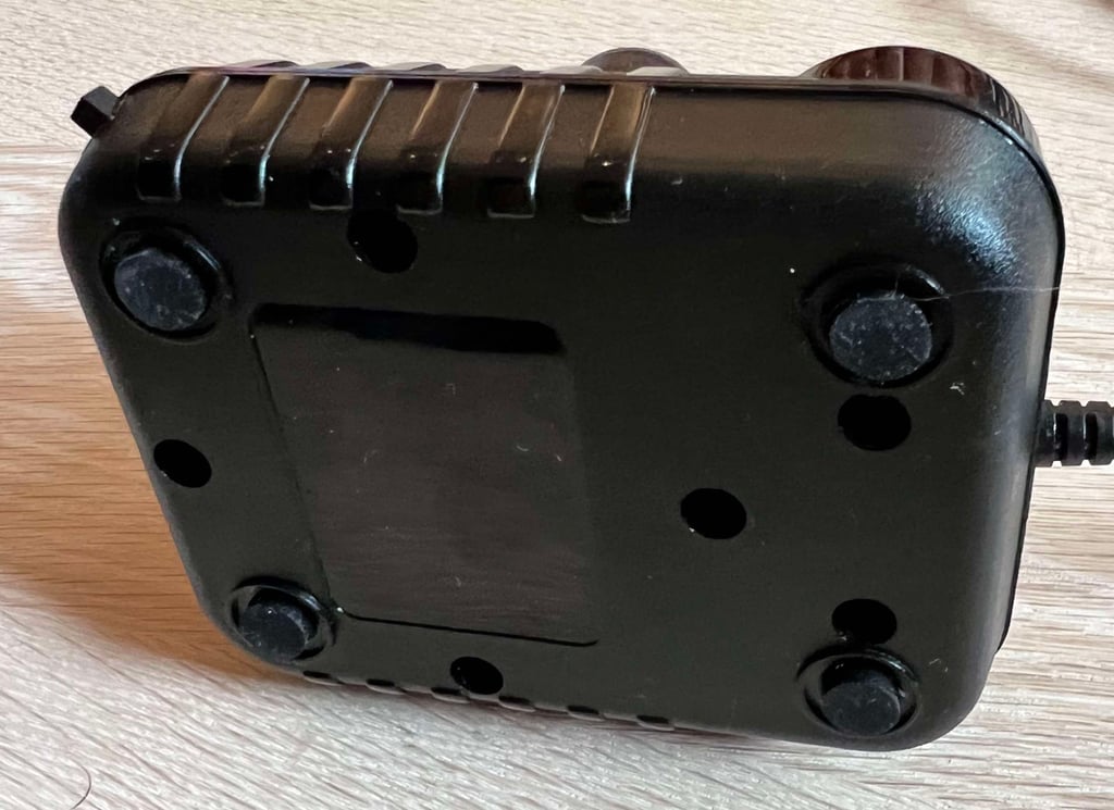
All the six microswitches produce a nice and clear clicking sound. The autofire switch also appear to be in good condition, but these are known to be a bit wonky. I can not see any mechanical damage on the casing, except for some marginal tear and wear. The strain relief, cable and connector all look fine. All the bottom cover all the four suction cups have been removed.
Below are some pictures of the Zipstik joystick before refurbish.




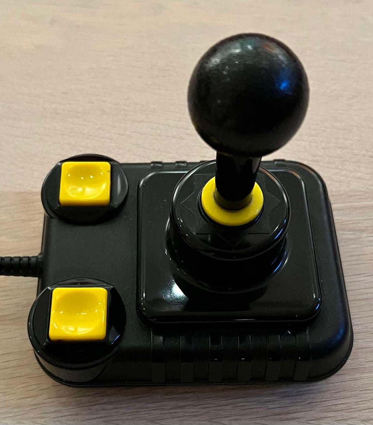

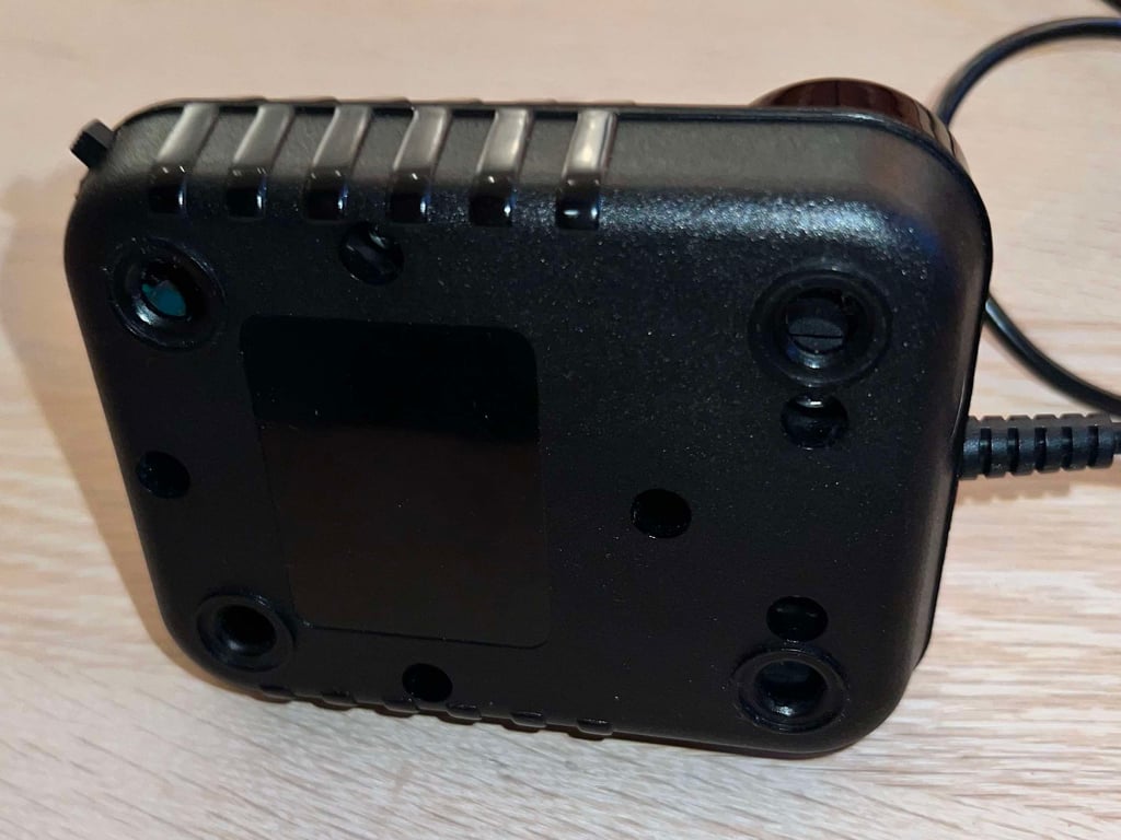

Refurbishment plan
To refurbish this joystick the plan is to do this trough the following steps:
- Clean, and remove stains from, chassis and all parts (and repair if required)
- Lubricate moving parts
- Clean and check the microswitches (and repair if required)
- Clean and check autofire PCB (and repair if required)
- Check connectivity (and repair if required)
- Verify joystick operation by testing
Disassembly
The five screws at the bottom are removed first.
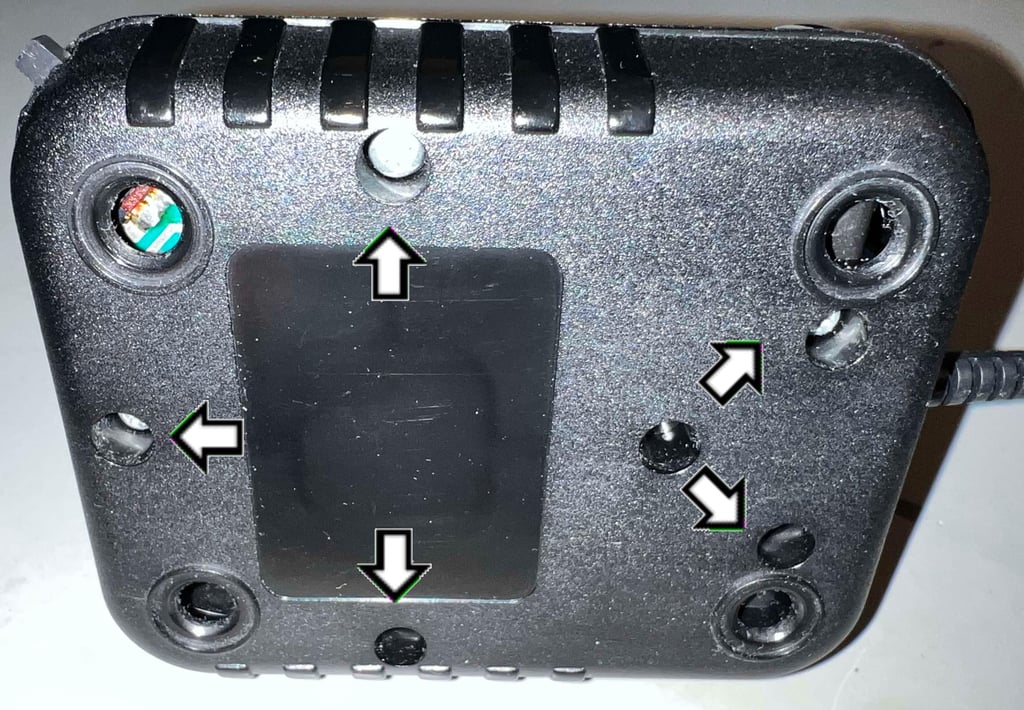

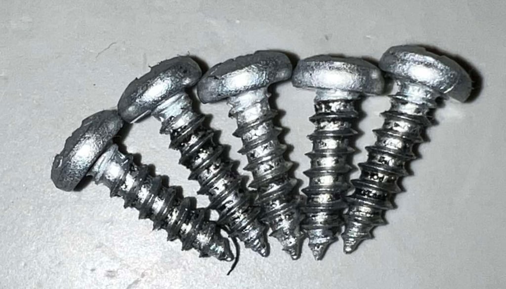
All of the three screws are of the type Pozidrive 3.5 x 13.5 mm, and appear to be in good condition.

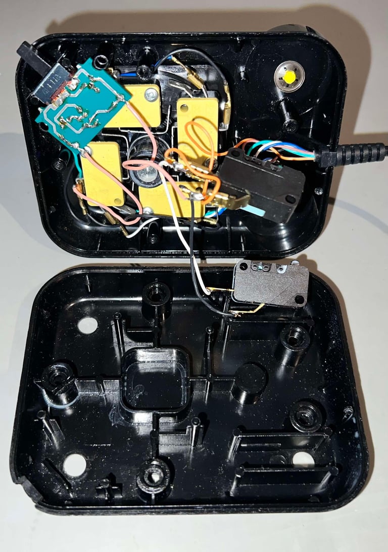
With the screws out of the way the top cover is carefully lifted off. And what a surprise inside! What I immediately notice:
Four out of the six microswitches are marked "Zippy". I highly doubt that these are original, both because I have never seen such a brand in a Zipstik, but also because they have levers and an additional connector. Why?
The interior has been lubricated. Although, I think that lubrication is a smart thing the amount of grease used is a bit too much. As far as I know no original Zipstik was lubricated. This is something that is done when refurbishing them later.

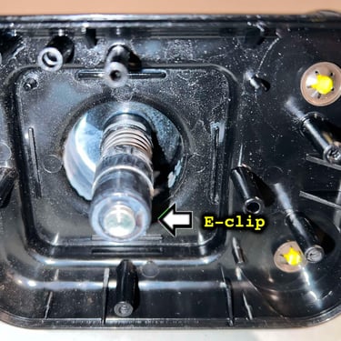
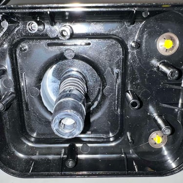
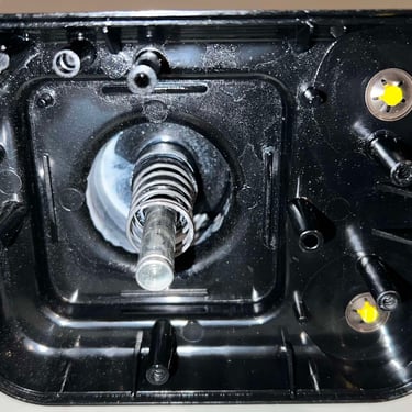
To disassemble the joystick shaft the E-clip at the bottom of the metal rod is removed first. Then each part is removed one bye one. Notice in the picture gallery that all parts have been lubricated previously (again, which I think is a good idea!).
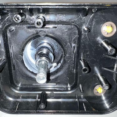
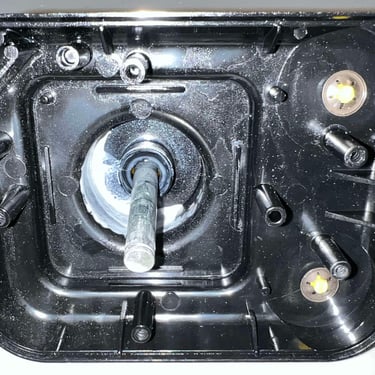
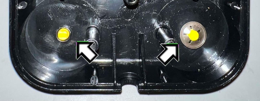
Disassembling the two FIRE buttons are a bit more tricky. With some sharp, thin picking tools the small locking rings are carefully removed and the FIRE buttons disassembled.

Exterior casing and plastic parts
Both the top- and bottom cover are in good condition. There is a substantial amount of grease on the top cover (which I think is good actually), but all of this will be cleaned off before new grease is applied.
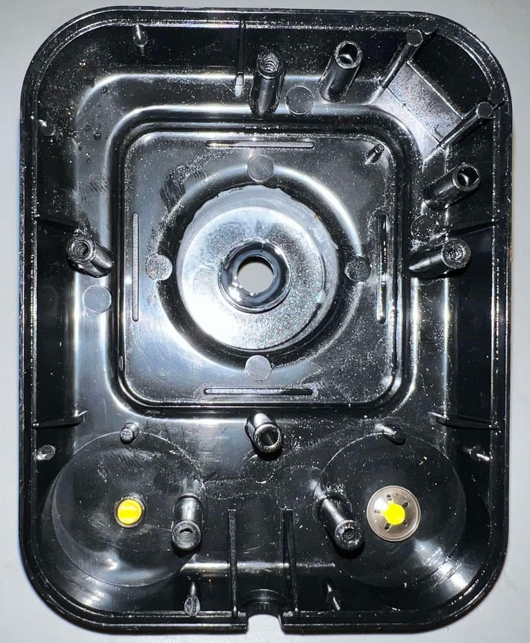

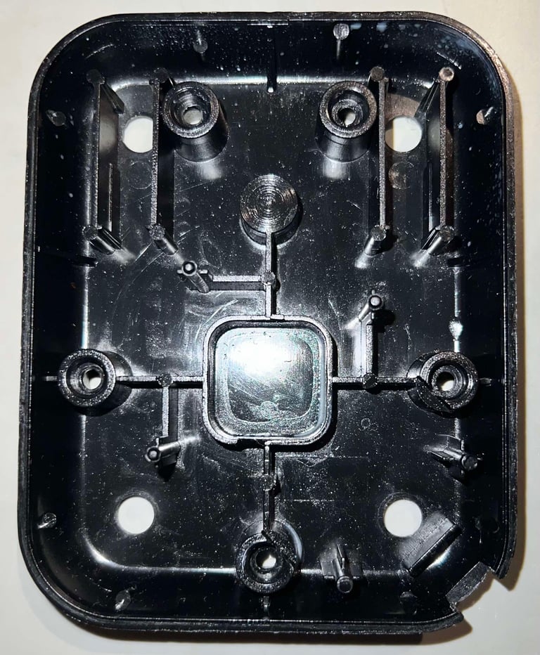

The same condition goes for all the parts. There is some grease on some of them, but they all appear to be without any damage.
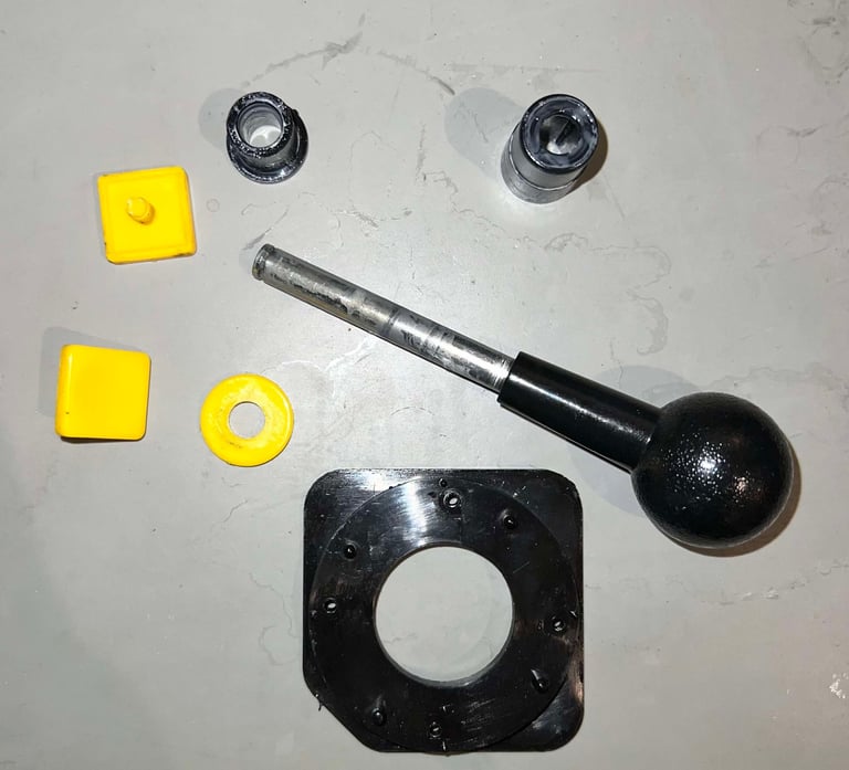

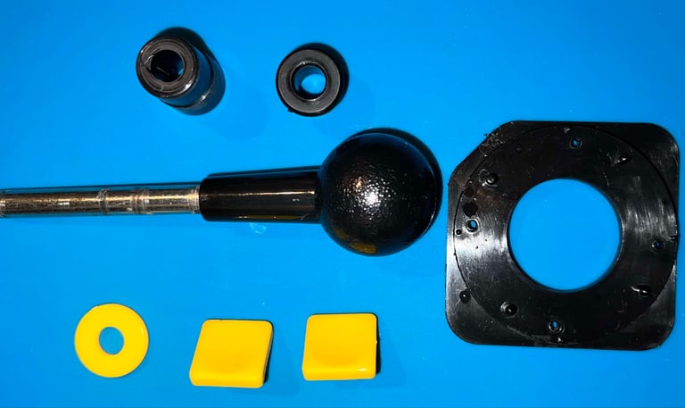
All the parts are soaked in mild soap water for about 48 hours. This will (hopefully) remove most of the grease.
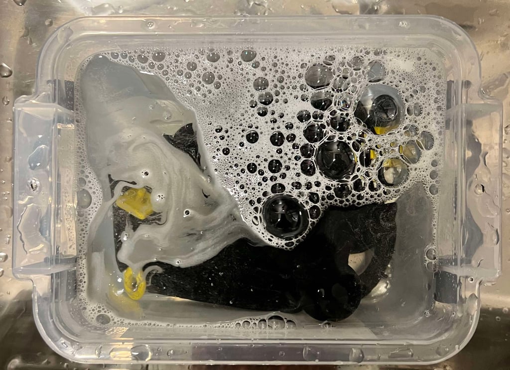

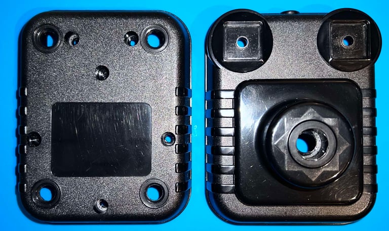
The plastic parts had to be soaked for almost 4 (!) days before the old grease came off. And I really wonder what kind of grease this was. I smells almost like what is known as "white spirit" in Norway. Like a thin oil for removing paint. But in the end, everything came off. As can be seen below the parts look good as new.


Adding rubber feet
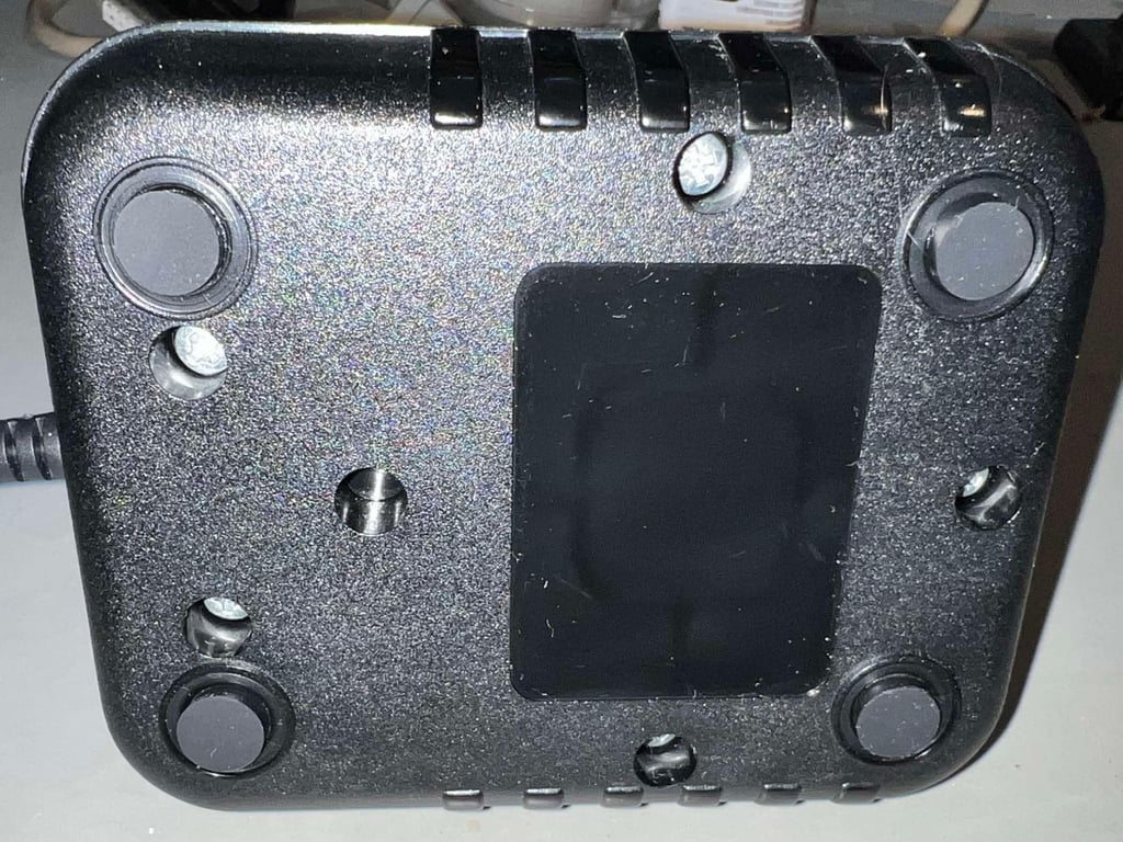
After everything is re-assembled some new 10 x 3 mm rubber feet are added to the bottom cover. This will prevent both dust from entering the interior and also the joystick so slide while seated on a table.

Lubricating selected parts
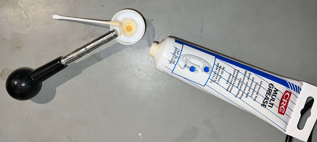
As previously mentioned this joystick was lubricated before refurbish. I think that adding some small amount in the Zipstik is a wise idea. It will reduce friction, noise and provide a more smooth handling. But compared to previous lubrication, I use a more gentle multi purpose grease. They are probably fine both of them, but the multi purpose is less oily and smelly. Note that is is just the metal shaft, and in the inside of the plastic parts which are in direct contact to the metal shaft, that are lubricated.

Electronics and microswitches
Visual inspection
Before doing any interior refurbish of the Zipstik a visual inspection is done first. And what I notice:
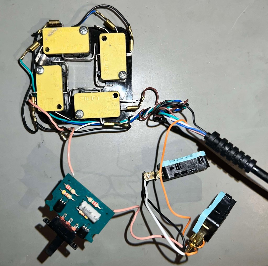
Four out of the six switches used for the LEFT/RIGHT/UP/DOWN direction are branded "Zippy" instead of "Crouzet". It is common that there are different brands for the microswitches used the directions, but I have never encountered "Zippy". I can be wrong, but I do not think that these were installed at production time. Why? First; I have never seen these before. Second; why use microswitches with both long unnecessary handles and unused connectors? Third; there is quite some grease on them. And even if it is a good idea to use some grease I do not think this was done at factory.
The FIRE button microswitches are branded "Crouzet" which is very common in Zipstik
Most of the microswitches have cable shoes, but a few don´t. Appear to me as a sign of rework.
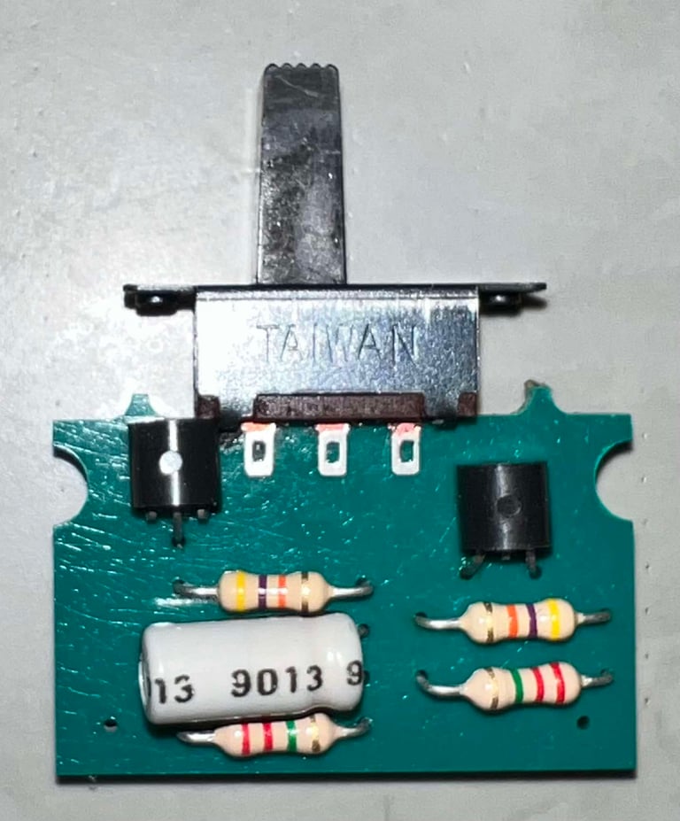
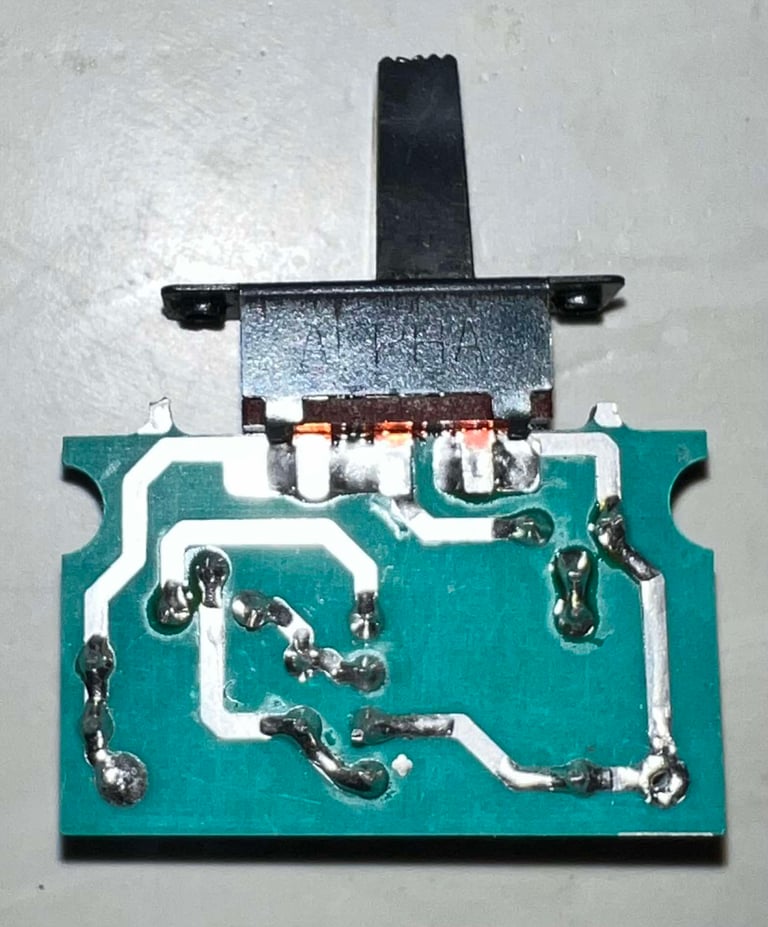
The AUTOFIRE PCB appears to be in ok condition, but the small 1 uF [63 V] capacitor seems quite worn out. The AUTOFIRE switch does appear to be fine too(!). This is often not the case.
Cable, wires and connector all seem to be in good condition

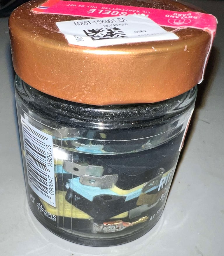
To remove most of the grease from the micro switches they are all placed in a jar filled with isopropanol for about 24 hours.

Replacing the non-original micro switches
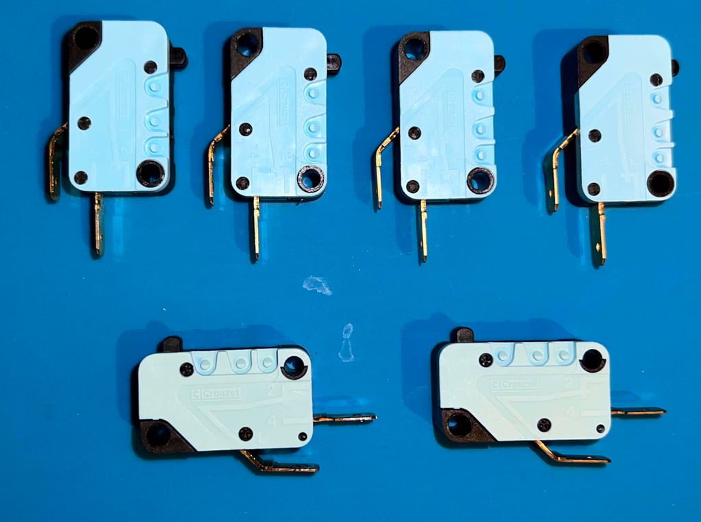
Even if the Zippy micro switches are ok, the owner of the joystick want to have it as original as possible so four brand new Crouzet branded. These are at the time of writing available at Mouser (Mouser No: 874-83161325 and Mfr. No: 83161325). Let´s enjoy international trade while we can!
Notice the color difference between the new (four top row) and old (two bottom row) on the micro switches.

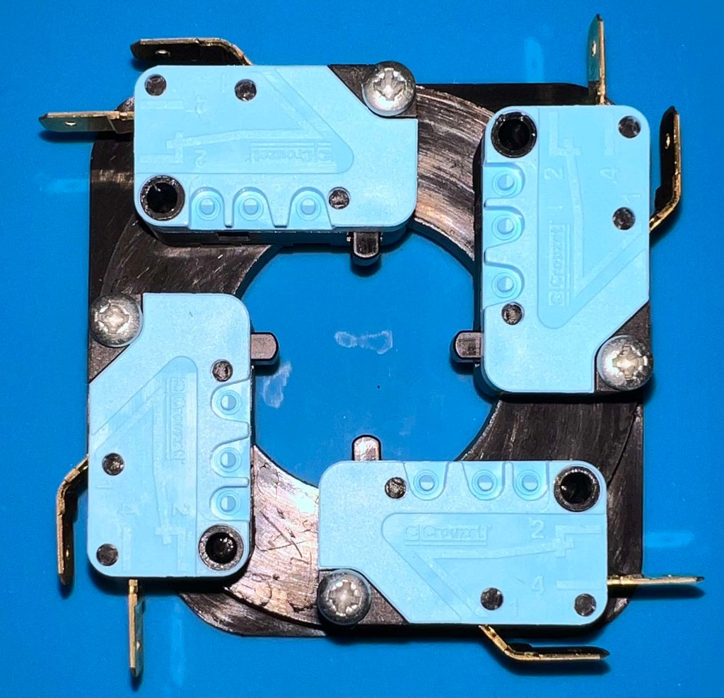
The four new micro switches are with the same form factor as the original, and matches the plastic bracket perfectly.

Replacing the electrolytic capacitor
In the AUTOFIRE a small electrolytic capacitor is used in the timing circuit. A dried out electrolytic capacitor in the AUTOFIRE is not the end of the world, but it is still good practice to replace these to get the Zipstik as close to the original as possible with modern parts.
NOTE: For some odd reason I completely forgot to take a picture of the cleaned, and refurbished, AUTOFIRE PCB. The PCB is properly cleaned, removing all residual flux. A 1 uF [63 V] capacitor is on the PCB originally, and a new Wurth Electronics capacitor 1 uF [50 V] is installed.
Below is a picture of the AUTOFIRE PCB before refurbish (as I completely forgot to take a picture of the refurbished).


Checking connectivity
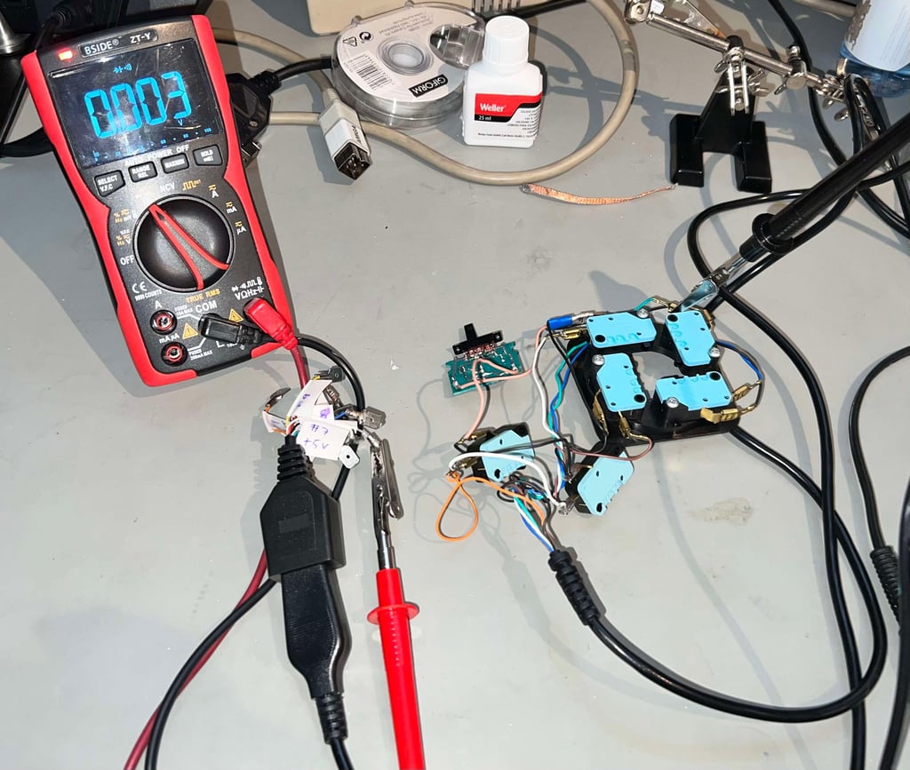
All the electronic parts are assembled; micro switches, wires and autofire pcb. After assembly the circuit is controlled for connectivity using a multimeter in "beep-mode". This is a quite efficient way of controlling that the wires and switches are working as it should, before assembling the electronics inside the casing.

Testing
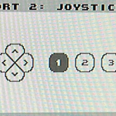
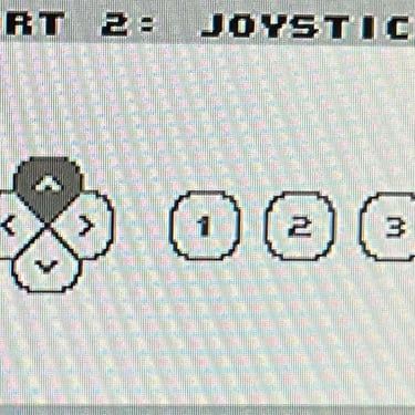
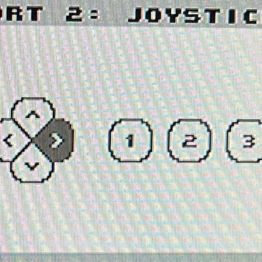
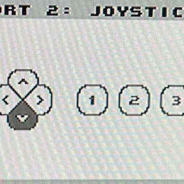
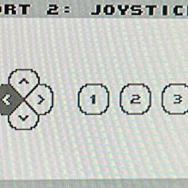
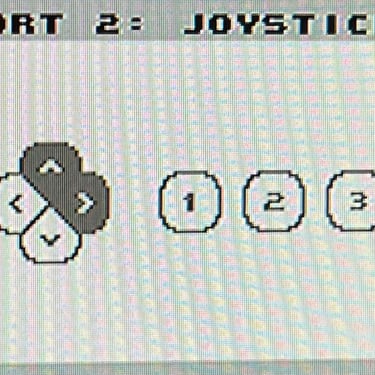
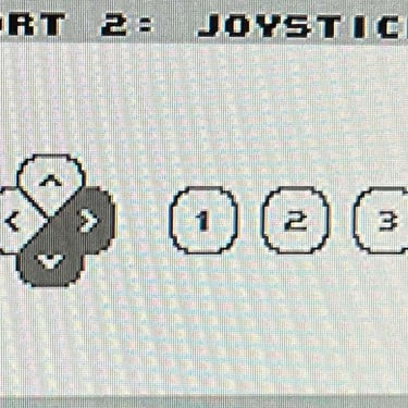
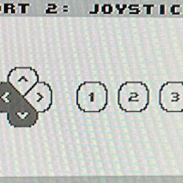
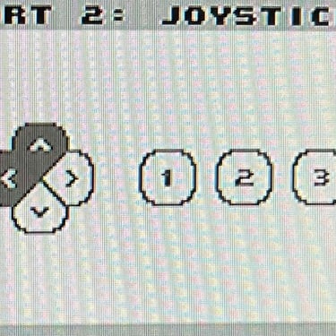
To verify that the joystick work as it should I check it with the Joyride software. Result is that all directions and fire buttons works fine works as expected. All tests pass.
Final result
"A picture worth a thousand words"
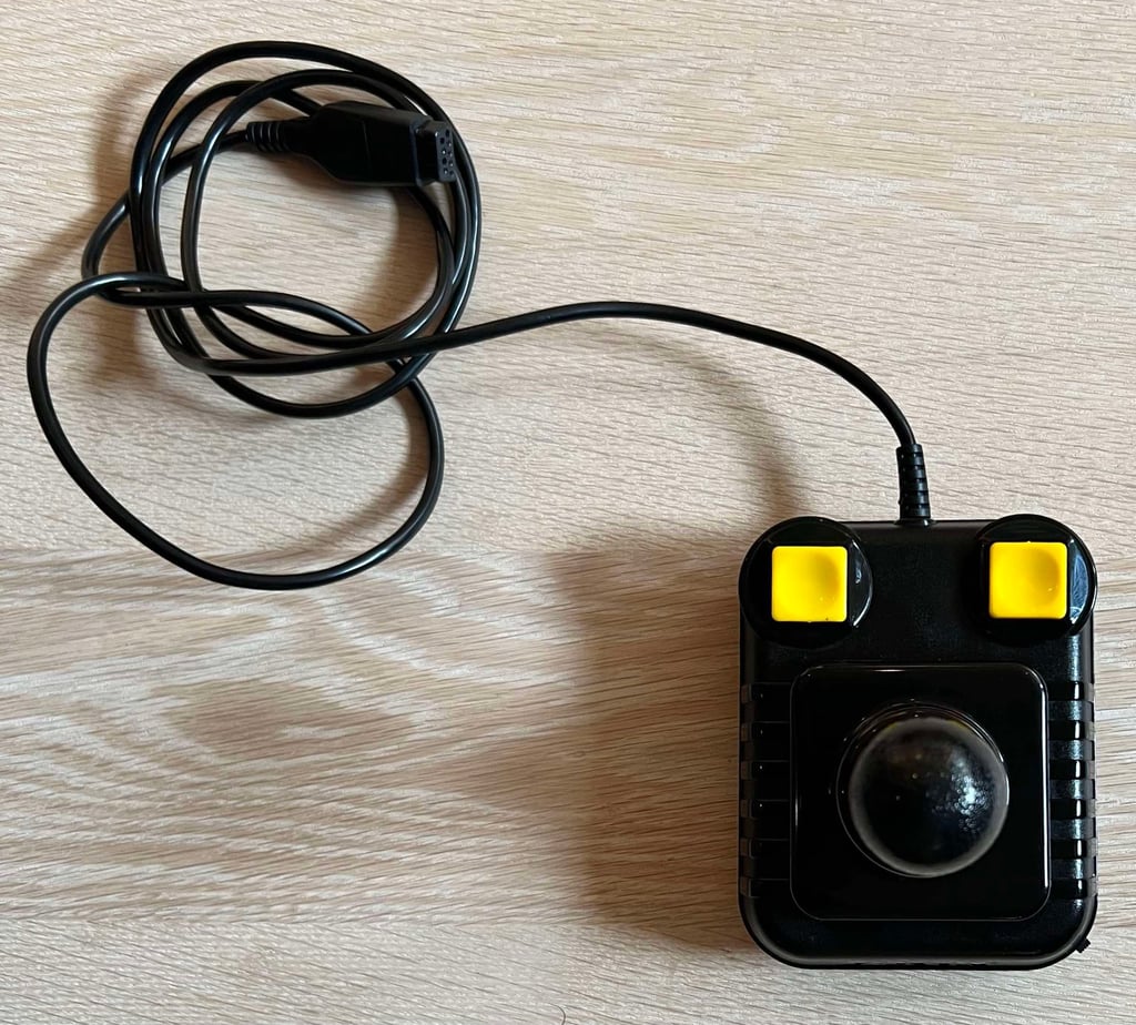
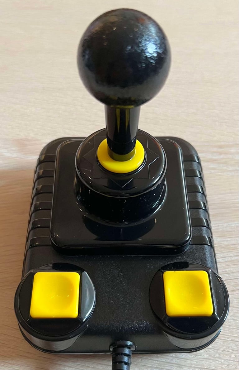
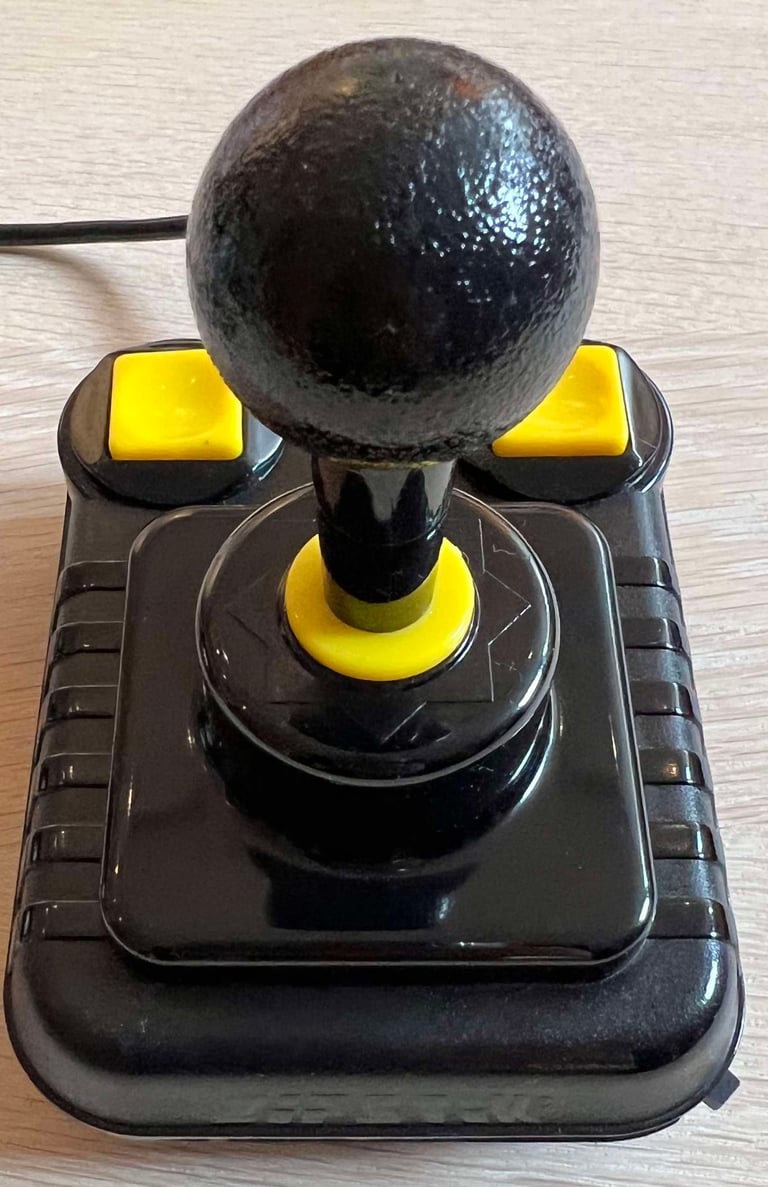
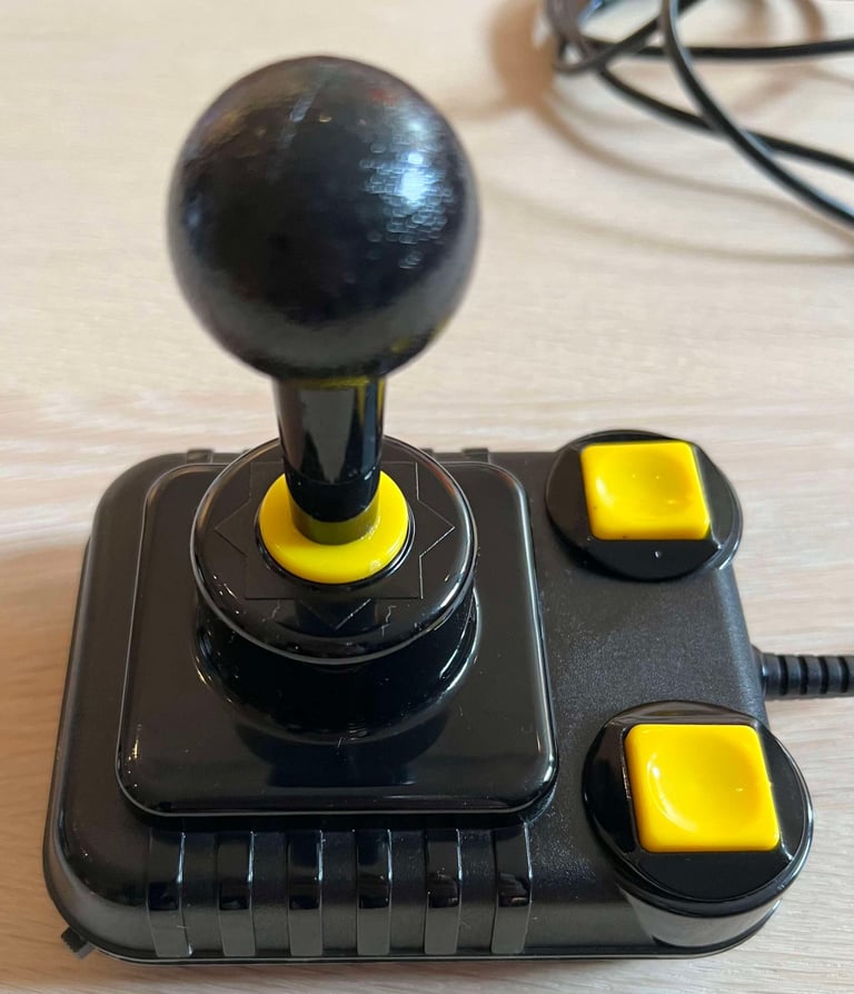
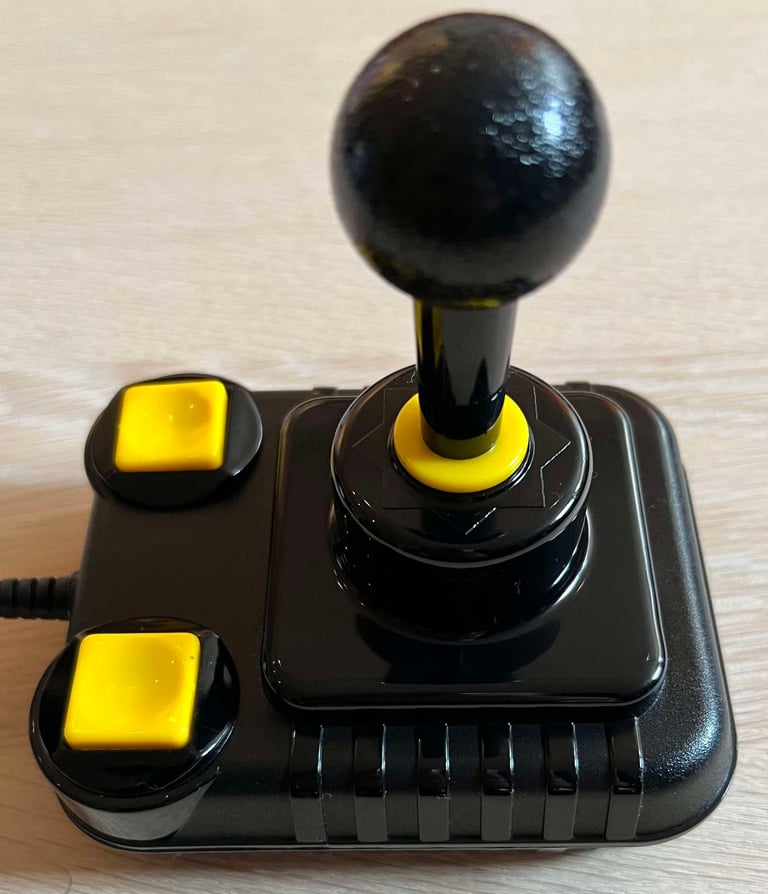
Below is a collection of the final result from the refurbishment of this Zipstik joystick. Hope you like it! Click to enlarge!






Banner picture credits: unknown
