

Zipstik
Starting point
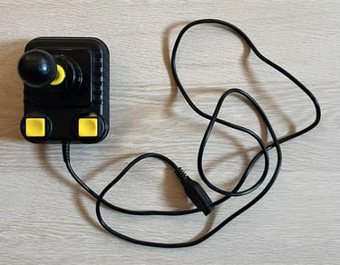
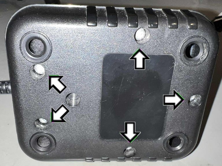
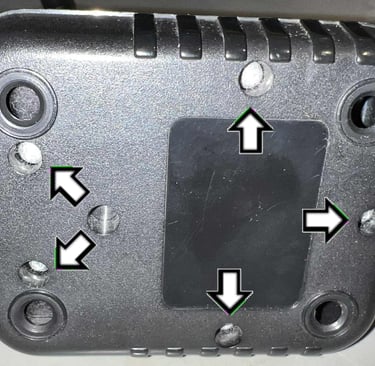
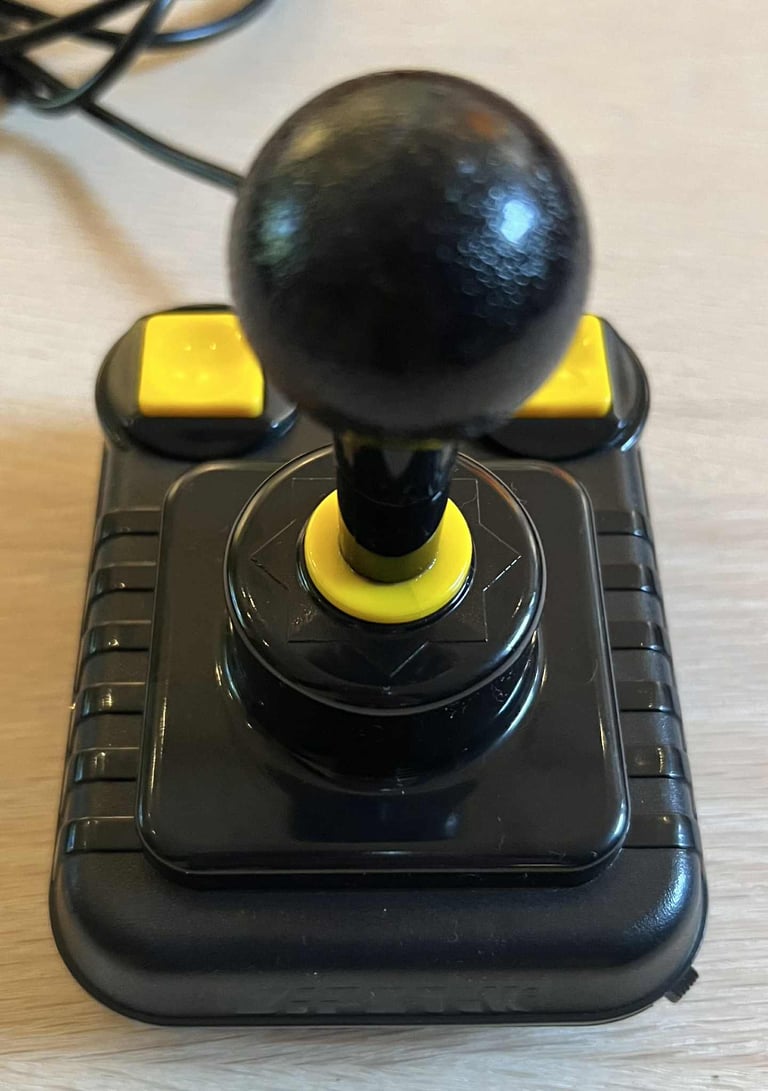
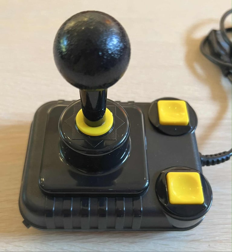
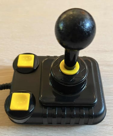
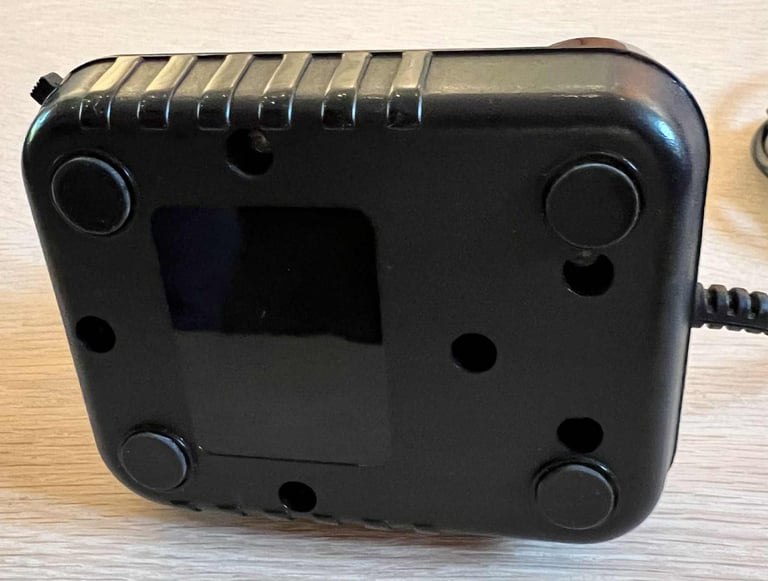
The main purpose of refurbishing this joystick is to add an autofire function to it (and the same goes for this Zipstik). The plan is to carve out an area on the right hand side (rear) to allow for an autofire circuit and switch. In theory (?) the bottom cover of a non-autofire joystick is the same as the version with autofire - the only exception is a small area where the switch protrudes.
Nevertheless, the joystick would benefit from some cleaning also. It is not very dirty (not at all), but there are some grease and grime which needs removing. And I do not know if it works. All mechanical parts feel, and sounds, to be in good condition. That also applies for the cable and connector as far as I can see.
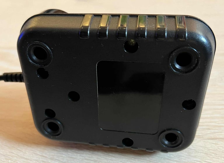
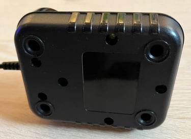
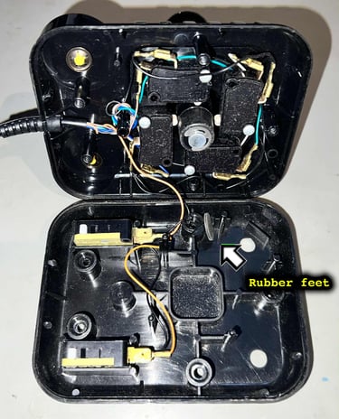
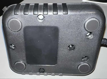
One thing I notice is that the rubber feets are missing. This is something I notice on many of these joysticks. If they are removed deliberately, or simply fallen off, I do not know.
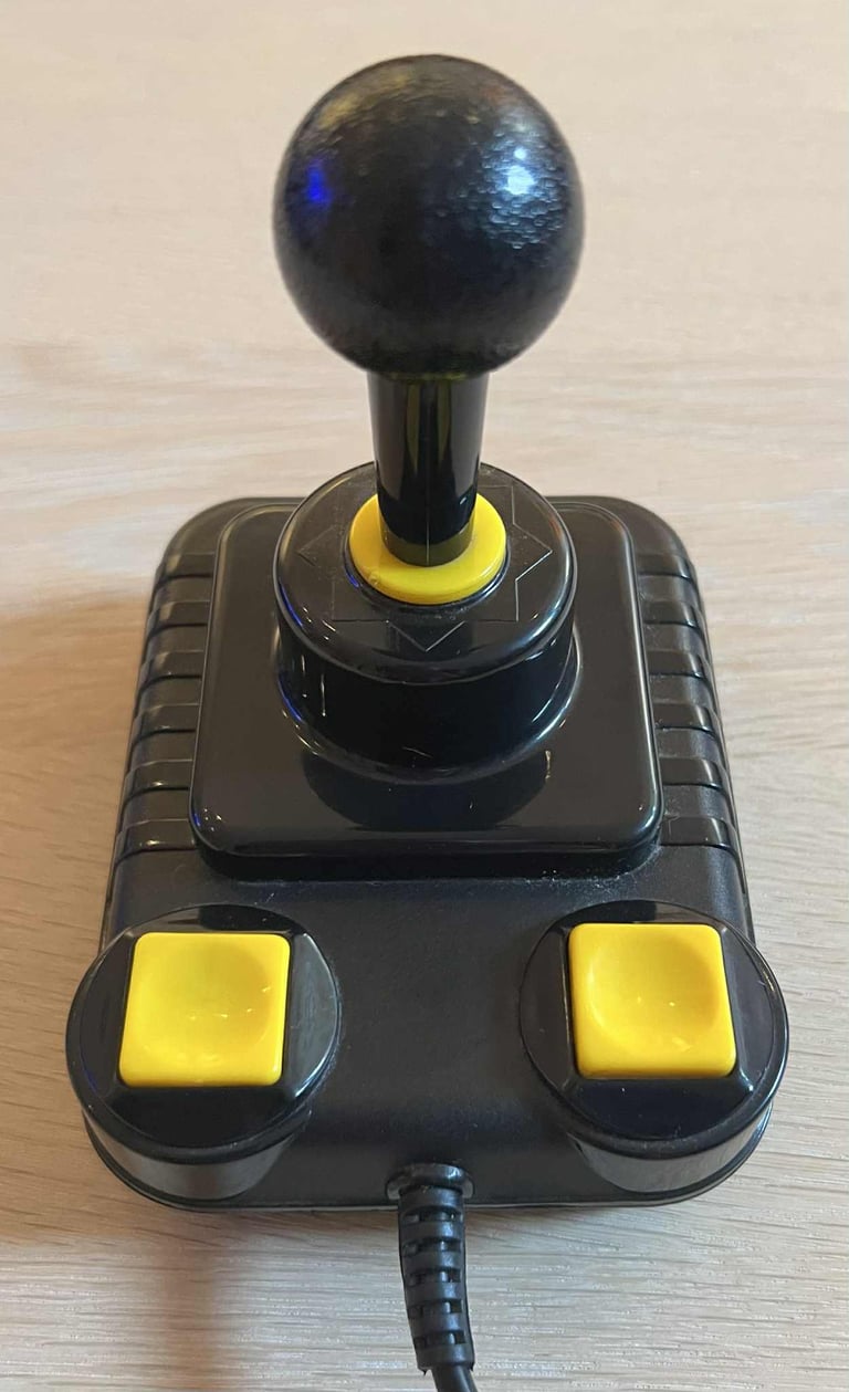
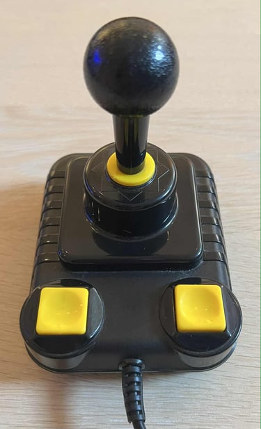
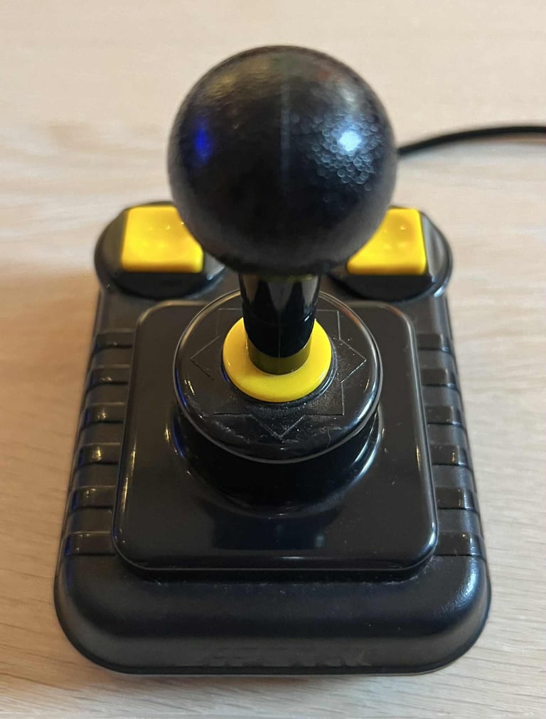
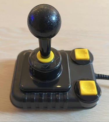
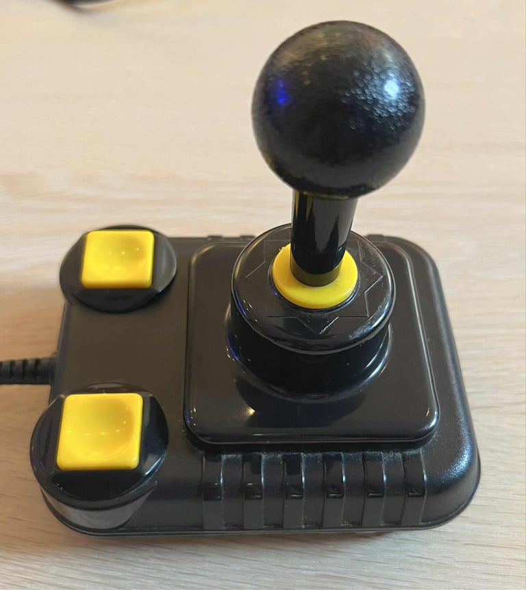
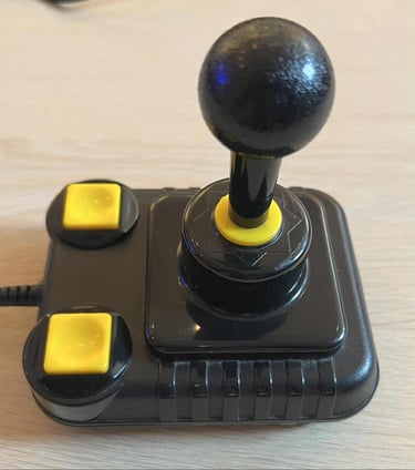
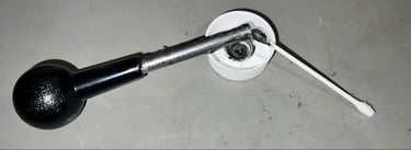
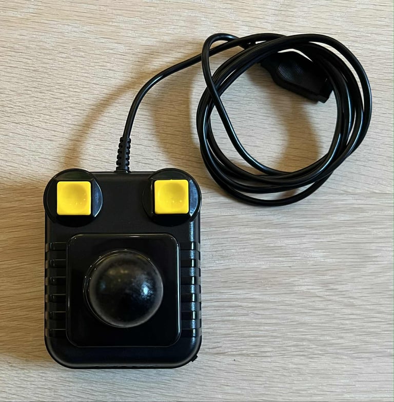
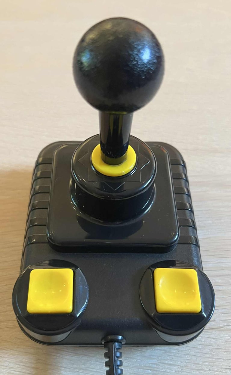
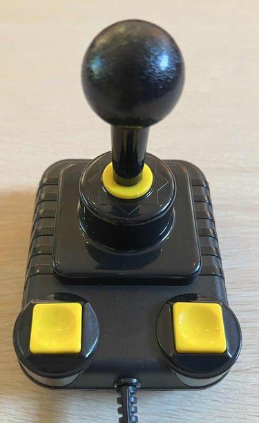
Below are some pictures of the joystick before refurbish.


Refurbishment plan
To refurbish this joystick the plan is to do this trough the following steps:
- Clean, and remove stains from, chassis and all parts (and repair if required)
- Lubricate moving parts
- Clean and check the microswitches (and repair if required)
- Add autofire PCB
- Check connectivity (and repair if required)
- Verify joystick operation by testing
Initial test
Before any refurbishment start the Zipstik joystick is tested with a known working Commodore 64. And the joystick does seem to be working. All directional motion (LEFT/RIGHT/UP/DOWN) and the both FIRE buttons are registered OK. See table below.
Disassembly
Disassembling the covers and microswitches
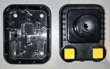
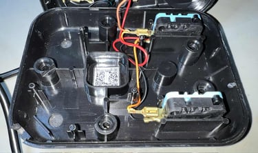
To disassemble the Zipstik the five 3.5 x 13 mm Phillips screw are removed from the bottom cover.
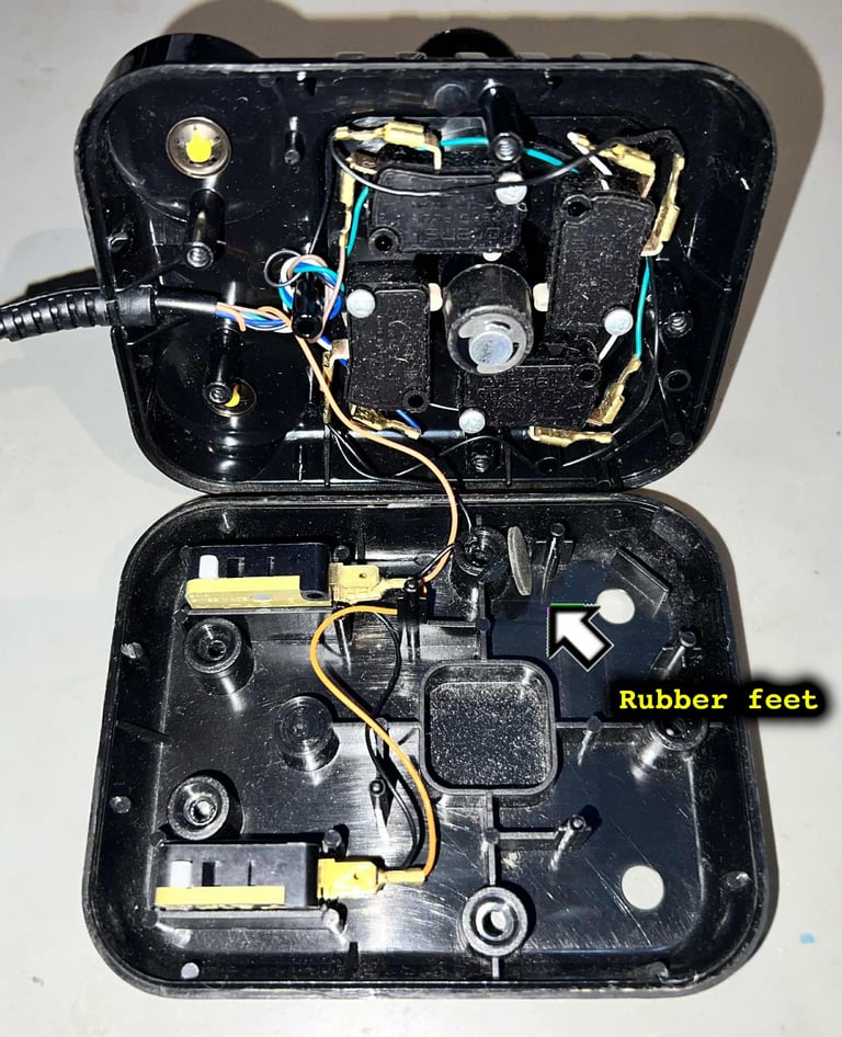
The top cover is carefully lifted 90 degrees to reveal the interior. And, just as usual, there are quite some dirt and grease inside. Something I have seen several times working with Zipstik (and this is not an exception) is that the directional microswitches are covered with some kind of fine sticky dust. Also, there is a smell of "gammel kiste" (Norwegian) inside.
Another thing I notice is that one of the rubber feet are laying inside the joystick (!)
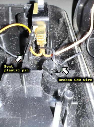
By closer inspection I also notice a few more things that needs to be taken care of later:
One of the plastic pins are bent. These thin plastic pins are supposed to be connected to directional microswitches (for stabilization)
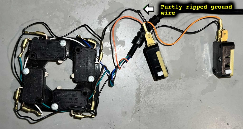
The ground wire connecting the FIRE buttons is almost completely broken. It is stuck in the screw hole. How this survived I do not know.

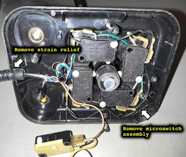
Next, the microswitch assembly is simply lifted away from the top cover. Note that the strain relief is also attached to the top cover so this also needs to be lifted away.

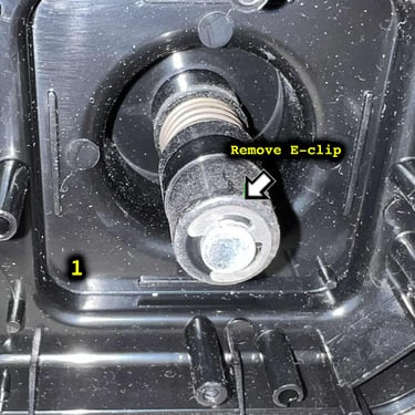
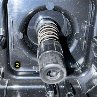
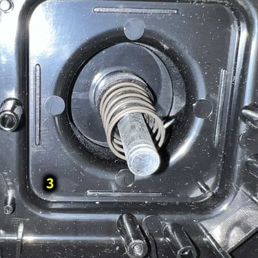
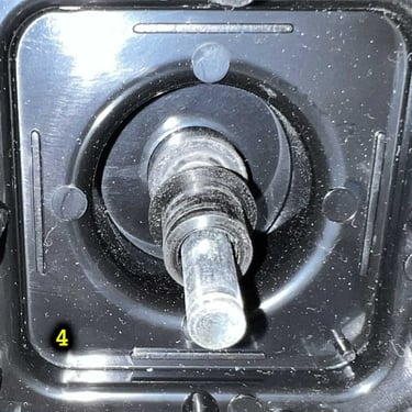
Disassembling the joystick shaft
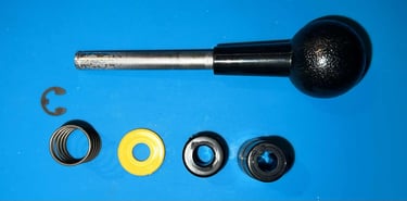
Disassembling is quite straightforward, but the key point to know is the order which the parts needs to be assembled. The first step is to remove the E-clip with a thin flat screwdriver, then the first plastic barrel, the spring and then the final plastic barrel. See picture gallery below (click to enlarge).
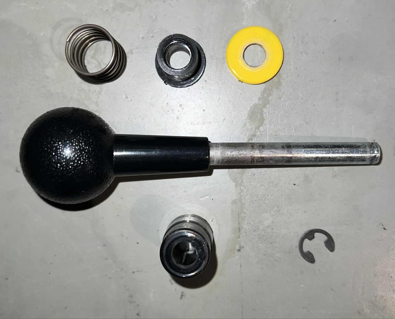
Below are some pictures of the parts after assembly. Note that the two FIRE buttons are not disassembled (this can be done, but do avoid risking damaging the buttons this is not done this time since they are in fine condition already).


Exterior casing and plastic parts
Cleaning the parts
Cleaning the plastic parts is straightforward. All the parts are placed in a box filled with mild soap water for about 12 hours. After the cleaning the parts looks very nice!


Lubricating moving parts
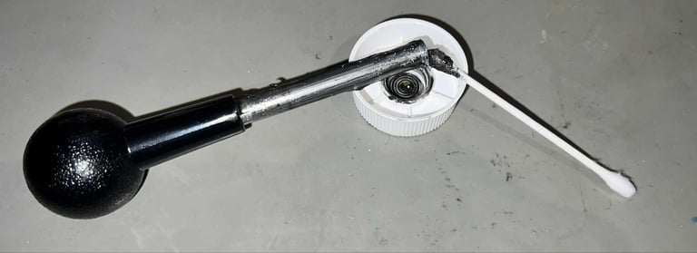
To reduce friction, and noise, the shaft and the inner plastic parts are lubricated with some grease. This is not strictly required, but I think it is good practice to do so.
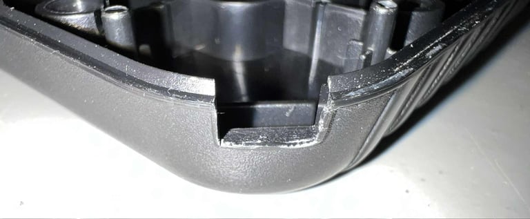
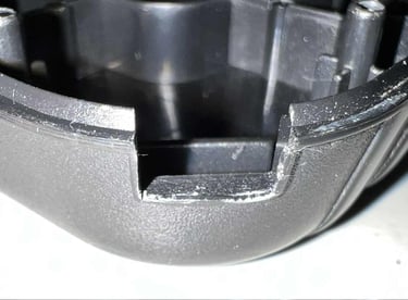
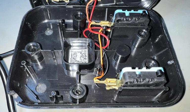
AUTOFIRE preparations
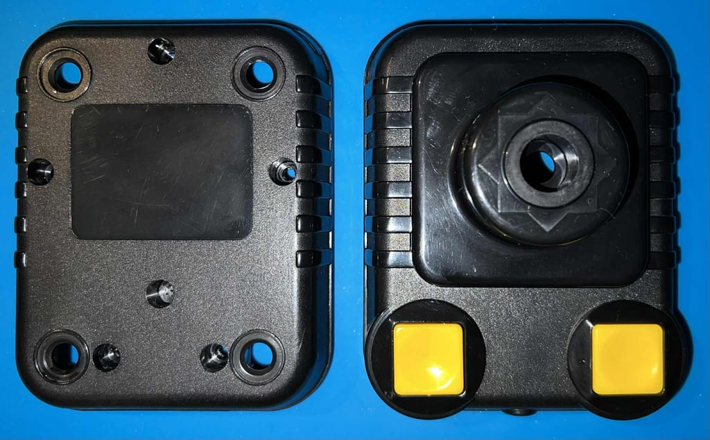
A nice feature with the non-autofire Zipstik joystick is that the covers can easily be modified to have a AUTOFIRE PCB and switch! In the bottom cover it is only a matter of cutting out a small area to make room for the switch. This is done by carefully using a sharp scalpel. The top cover on the other hand is already prepared for the AUTOFIRE PCB so no modifications are needed there.
Adding rubber feet
New rubber feet are mounted on the joystick. These rubber feet are ordered from retroleum.co.uk. The feet have double sided tape on the backside which makes this a simple and effective task.

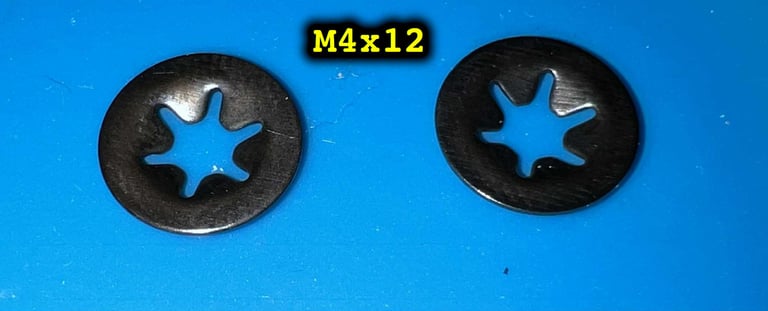
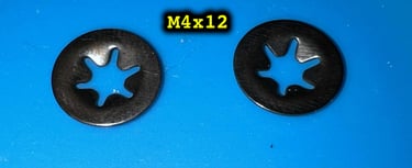
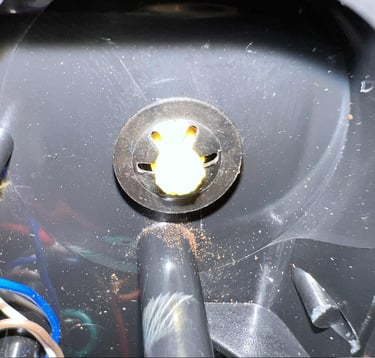
Replacing the tooth washers and lubricating the FIRE buttons
The original tooth washers are quite corroded. That is actually not a problem, but the FIRE buttons could benefit from some cleaning and lubricating. So, the old tooth washers are cut and removed. The FIRE buttons are cleaned with some isopropanol and the a tiny amount of silicon spray is added to the shaft. Finally some new M4x12 tooth washers are installed. Tip: it can be quite hard to press down a new tooth washer! By using a 5.5 mm "socket wrench" can be used to press the tooth washer in place.


Electronics and microswitches
Visual inspection
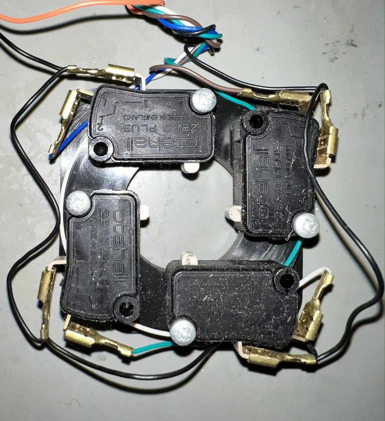
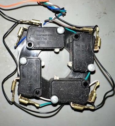
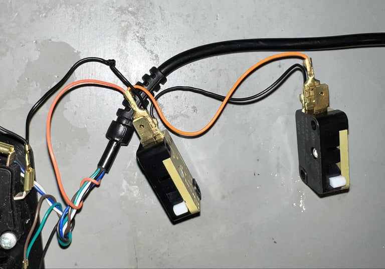
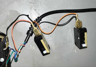
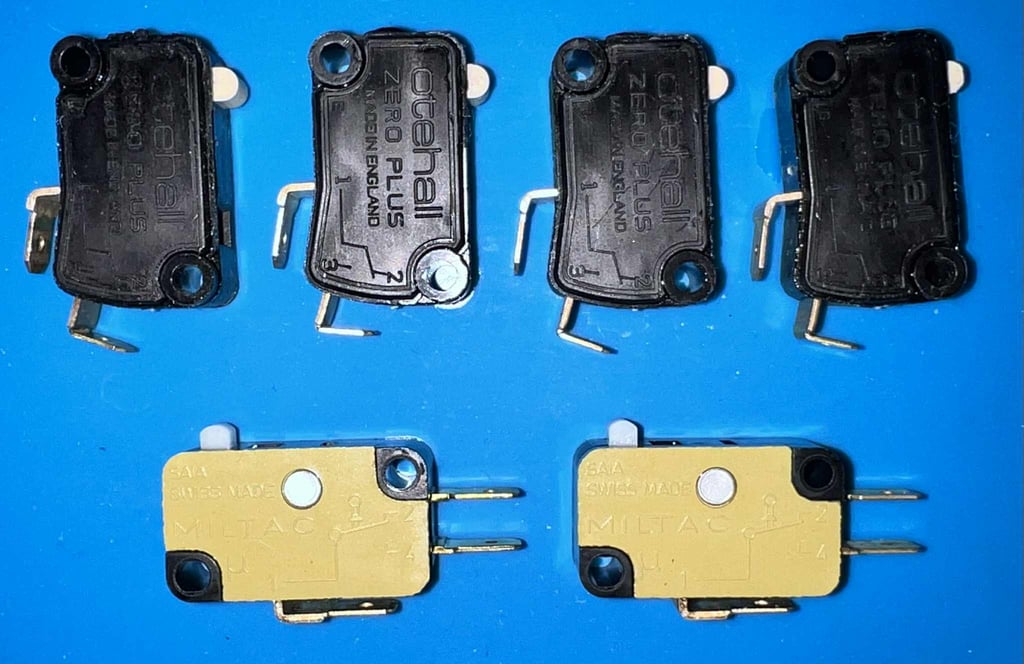
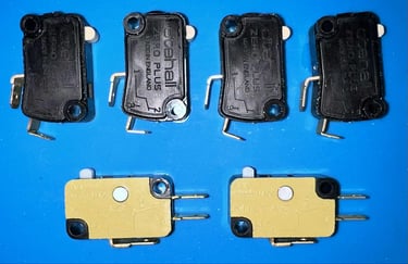
The electronic circuit is composed of four microswitches (Otehall Zero Plus) for the LEFT/RIGHT/UP/DOWN direction, and two microswitches (SAIA MILTAC) for the FIRE buttons. These are high quality microswitches and will probably work for a long time still.
There are two things which I notice:
As mentioned previously the ground wire attached to the FIRE buttons are completely smashed. This needs to be fixed.
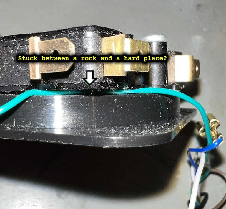
One of the wires are stuck between the microswitch and the plastic ring. This has probably happened during assembly.

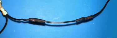
Repairing the ground wire
The ground wire is cut, and a small addition wire is added. To secure the new additional wire, the wire is both soldered at both ends and heat shrink tubes are installed.

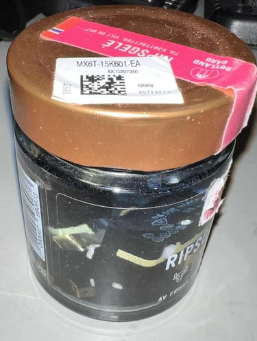
Cleaning the microswitches
The four Otehall microswitches are covered with some strange dust. This is something I have seen on several Zipstik joystick so this is very common, but I still do not know what causes this. All the microswitches are placed in a small jar filled with isopropanol for some hours. This should dissolve any dust and grease inside the microswitches.
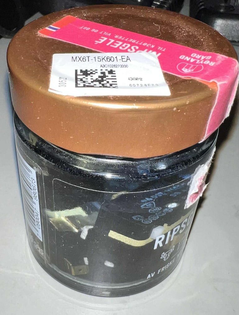
The microswitches looks really good after cleaning.
Adding the AUTOFIRE circuit
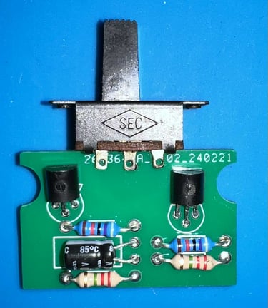
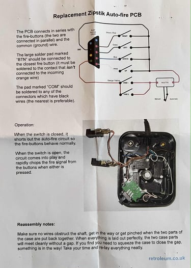
An AUTOFIRE PCB is sourced from retroleum.co.uk. This is a replica of the SAF-3 AUTOFIRE circuit found in original Zipstik joystick. A nice feature with this AUTOFIRE circuit is that it does not require a direct +5 VDC wire from the connector. As most of the Zipstik does not have this +5VDC wire connected this is a great benefit.
The circuit is made up of a PNP and NPN transistor (BC327 and BC547 respectively), a 1 uF capacitor, a resistor network and a swtich.

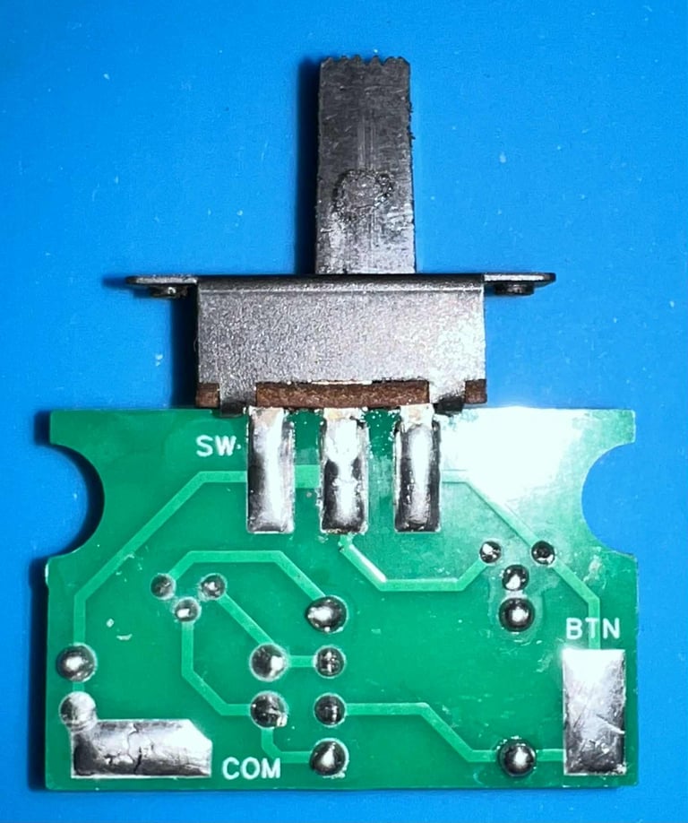
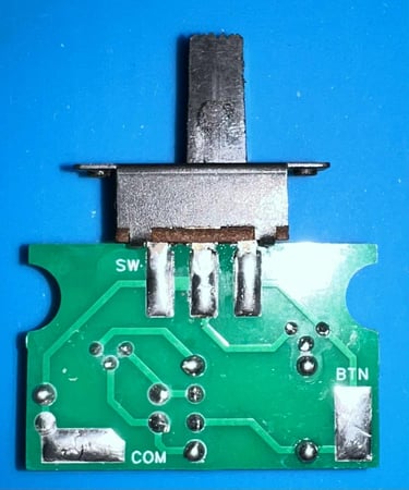
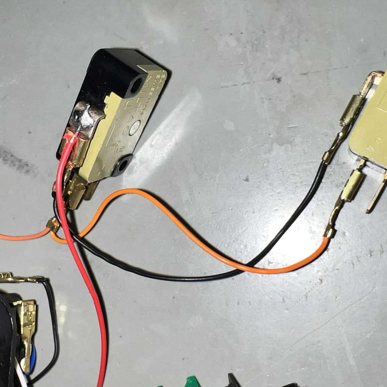
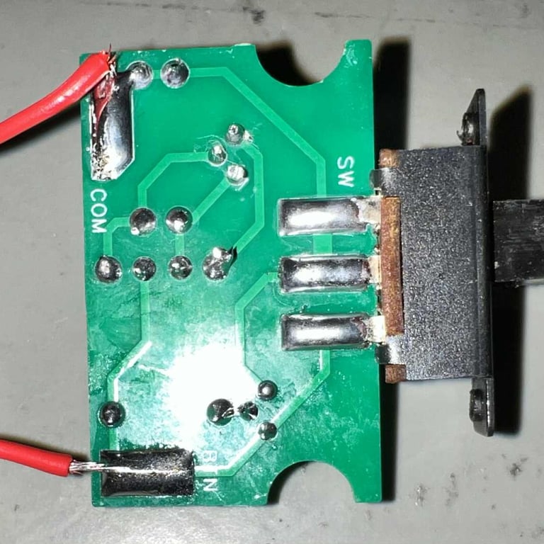
A detailed description on how to install the circuit is following the package from retroleum.co.uk. The installation is done by:
Cutting the GND wire connecting the first FIRE button in the chain to the LEFT/RIGHT/UP/DOWN microswitches
Soldering the previous "GND" wire on the first FIRE button to the BTN pad on the AUTOFIRE PCB
Soldering a wire from GND in the LEFT/RIGHT/UP/DOWN microswitch chain to the COM pad
Below are some pictures from the process. Click to enarge.
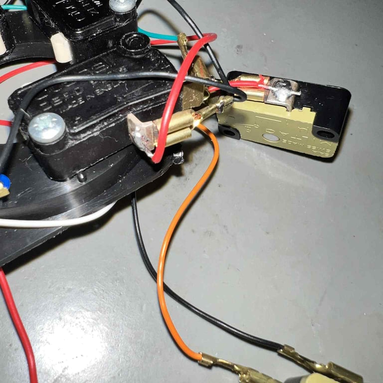

UPDATE: Both the FIRE button microswitches are replaced. Why? The owner of the joystick feels that the response from the FIRE button is not quite as good as it should be in a new Zipstik. So in an attempt to fix this the two FIRE button microswitches are replaced with new Crouzet switches purchased from Mouser (Mouser ID 874-83161325).
Testing
To verify that the joystick work as it should I check it with the Joyride software. Result is that all directions, fire buttons and autofire works fine works as expected. All tests pass.
Final result
"A picture worth a thousand words"
Below is a collection of the final result from the refurbishment of this Zipstik joystick. Hope you like it! Click to enlarge!


Banner picture credits: unknown