
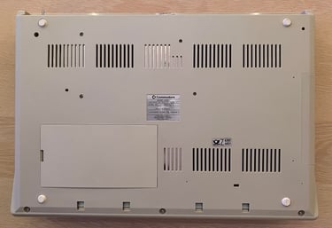
Amiga 500
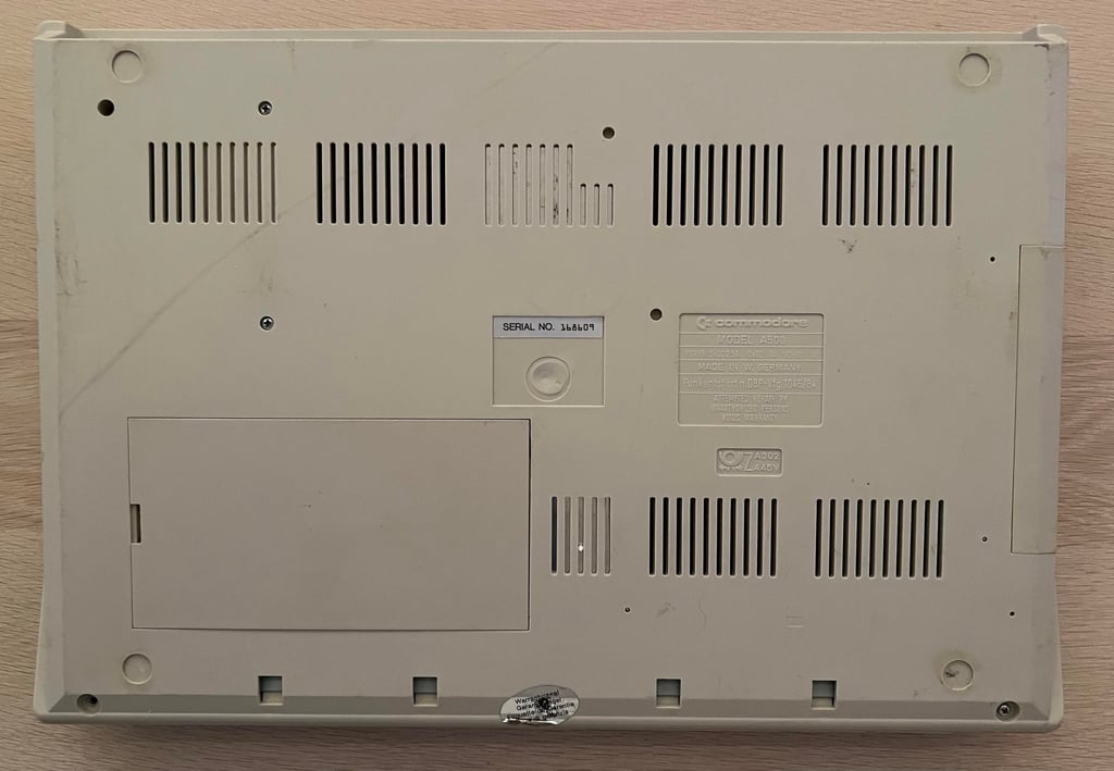
Ser. No. 168609
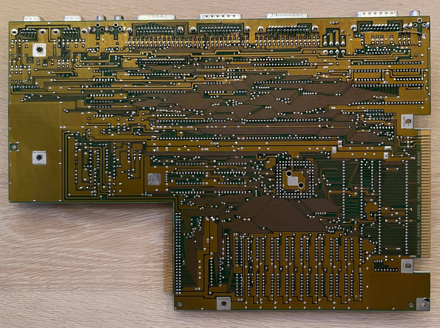
Assy 312510
Artwork 312513 REV 5
Starting point
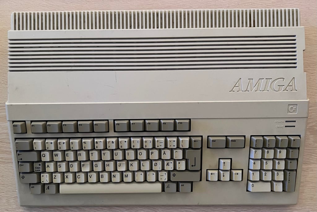
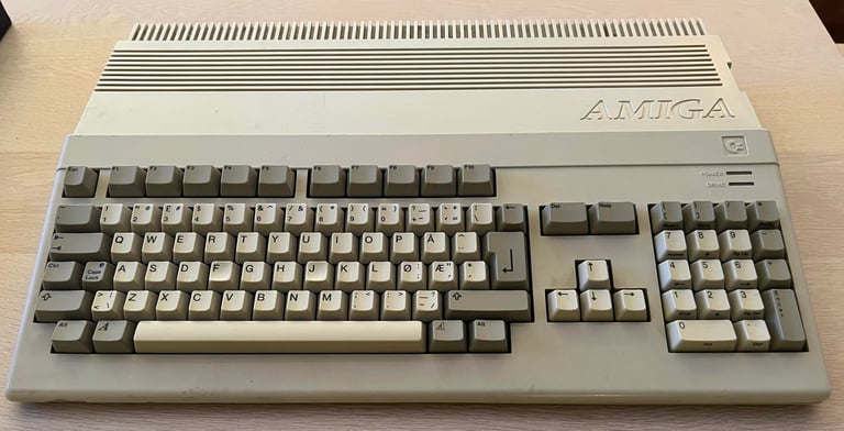
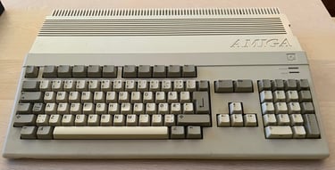
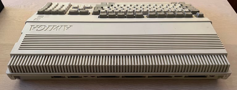
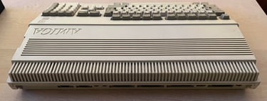
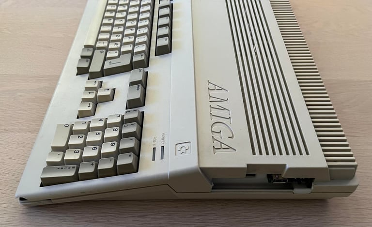
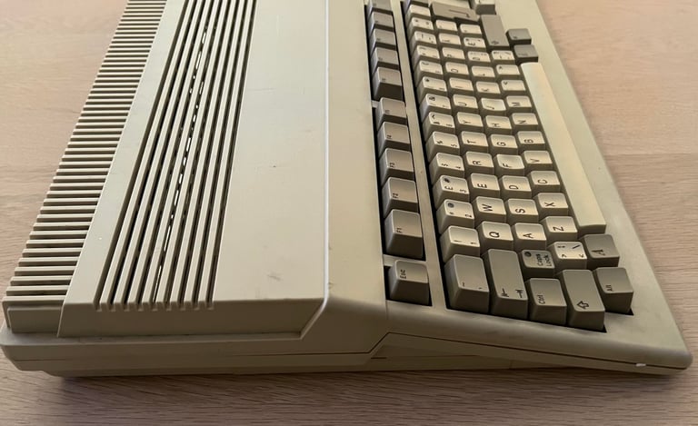
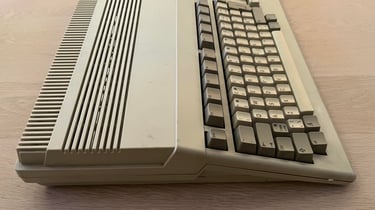
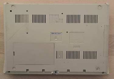
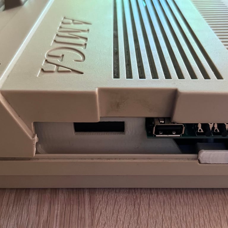
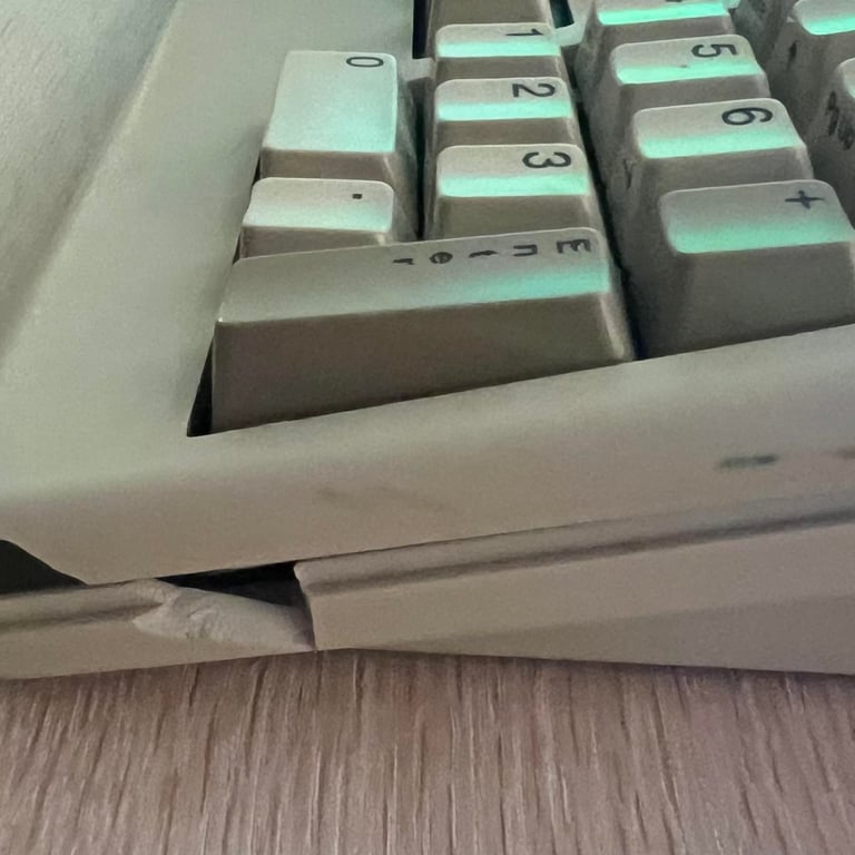
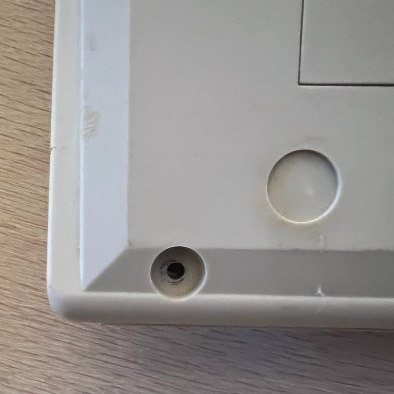
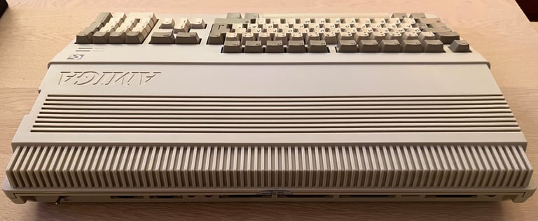
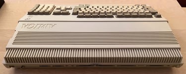
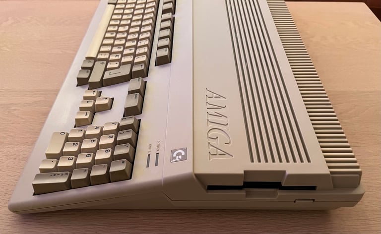
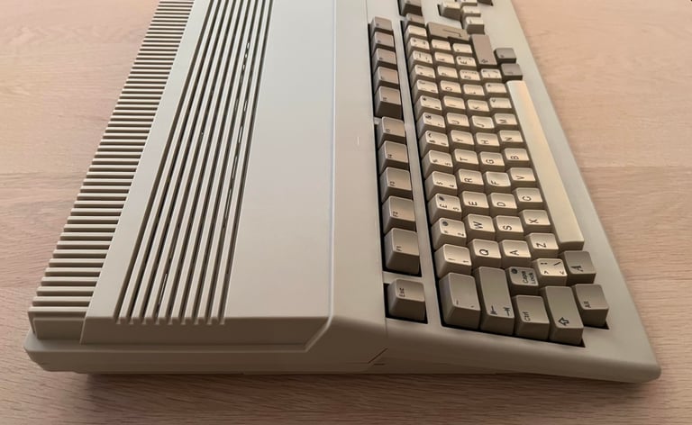
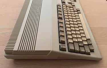
This Amiga 500 has come for some refurbish and changing/installing some peripherals. The machine is supposed to be in working condition. From the outside there the machine is somewhat dirty, but not too bad. But there is a crack in the casing and I can hear a rattling sound inside - is there a loose part inside? One of the case screws are missing also from the machine, but I find it laying inside the box is was shipped in.
Nevertheless, the owner wants to replace the broken casing with an undamaged original Amiga cover. Also, the owner wants the internal Gotek drive removed and instead replace it with an original Amiga floppy drive to make the machine really authentic. But to allow for a bit modern way of accessing software an external Gotek drive will be made available through an internal DF0/DF1 switch. I think that is an brilliant idea! (The idea is not mine but the owners).
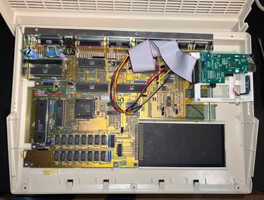
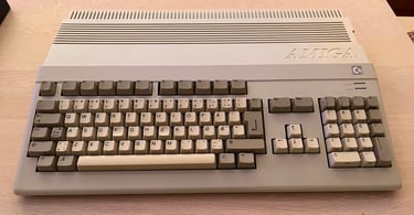
Below are some pictures of the machine before refurbish.


Refurbishment plan
To refurbish this Amiga 500 the plan is to do the following actions (several of them in parallell):
- Clean and revive the keyboard
- Change top- and bottom cover
- Refurbish the main board
- Refurbish the internal disk drive
- Replace internal Gotek drive with original Amiga internal disk drive
- Refurbish 512 kB RAM expansion card
- Install DF0/DF1 switch
- Install external Gotek
- Inspect external disk drive
- Verify operation by testing
Opens it up...
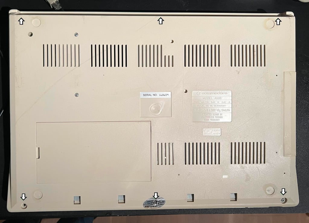
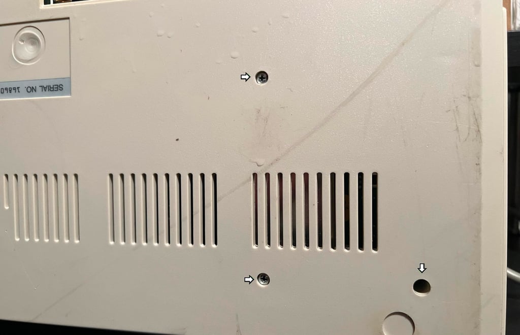
To open the Amiga 500 the six screws at the back are removed (one of these are already loose).

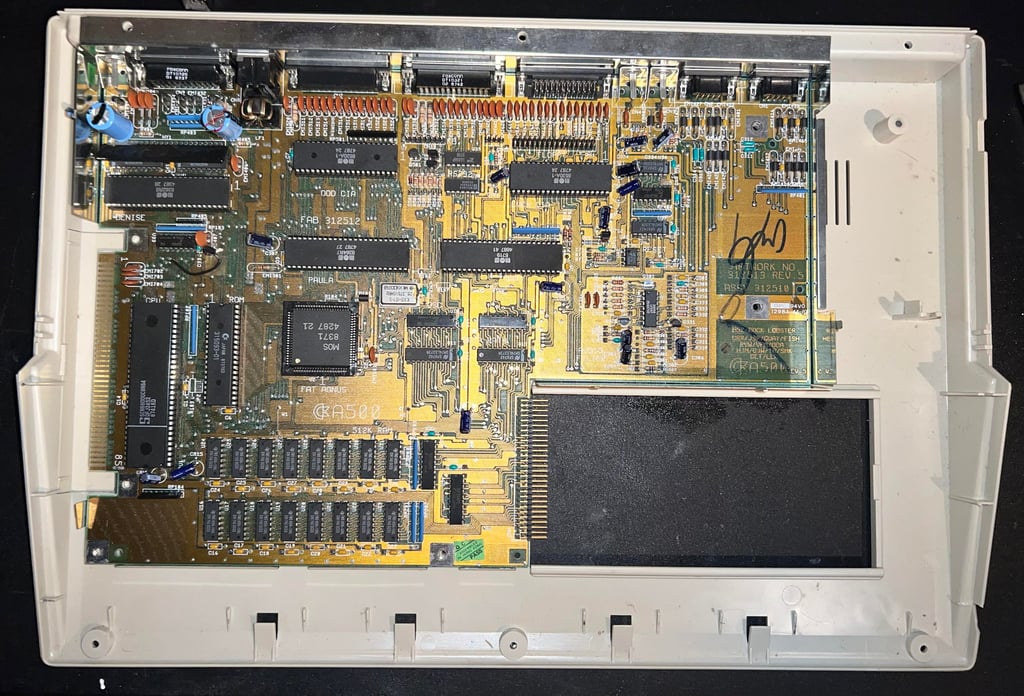
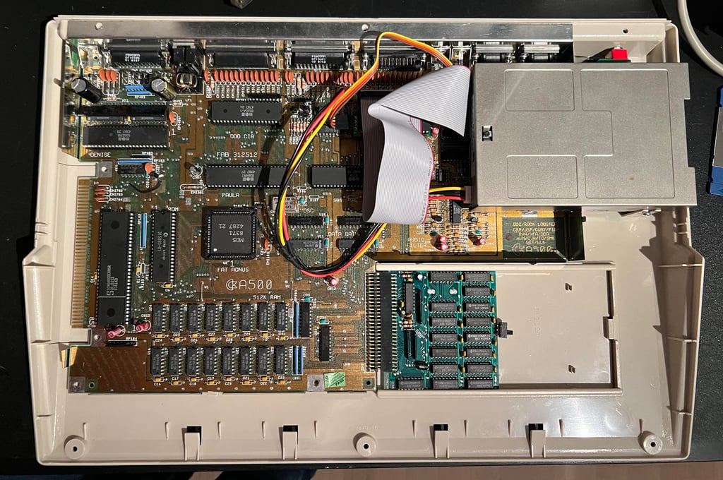
The machine is placed in its upright position and the top cover is lifted off. This reveals the inside which looks quite good. Only some minor dust - and I can´t see any corrosion on the RF-shield. The internal Gotek also looks to be in fine condition. The keyboard is a bit dirty, but that is normal.
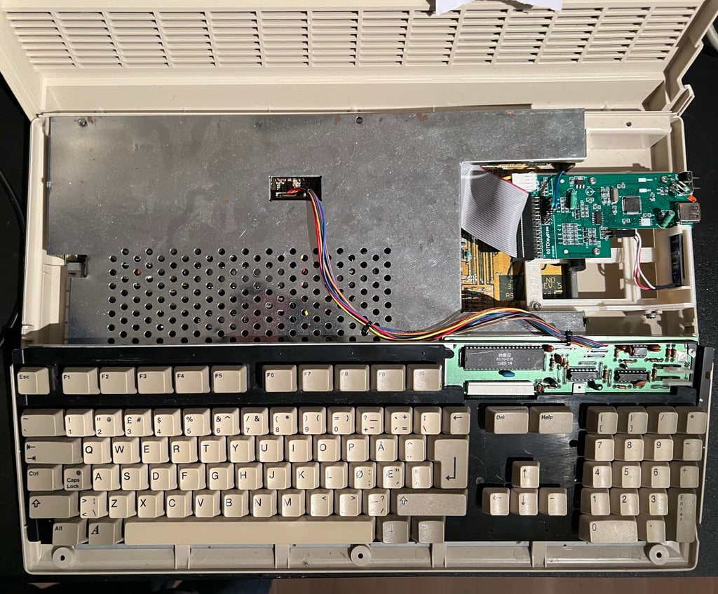
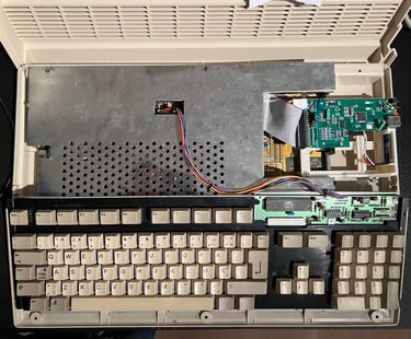

Next, the keyboard is removed by carefully disconnecting the cable. Now the whole RF shield is visible, and lo-and-behold there is a 512 kB RAM expansion in there! What a nice surprise! There are some leakage around the battery which is normal - and I will remove that later. The 512 kB RAM expansion card is removed together with the expansion port lid.


The four screws (pointing arrows) are removed from the RF-shield. And the three metal tabs are bent in upright position. Two of these are already bent upwards - no surprise but someone has been here before me...
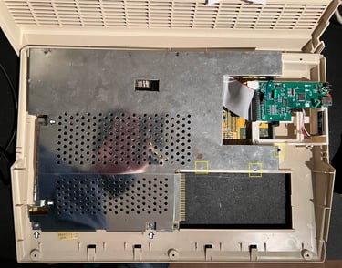
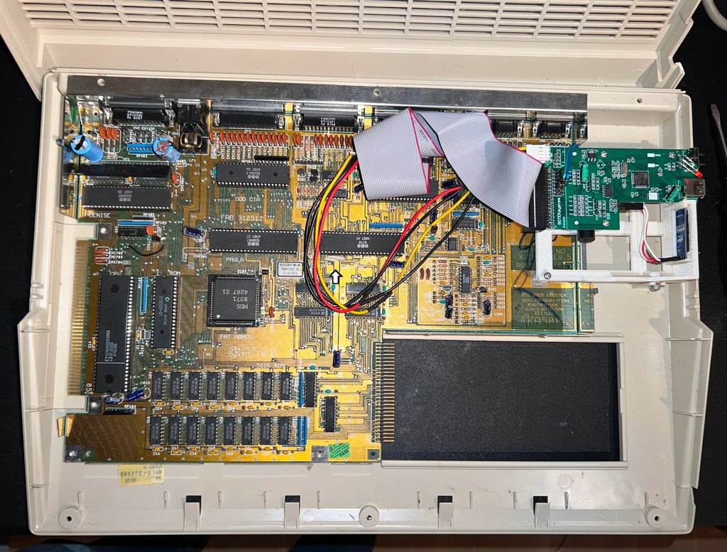
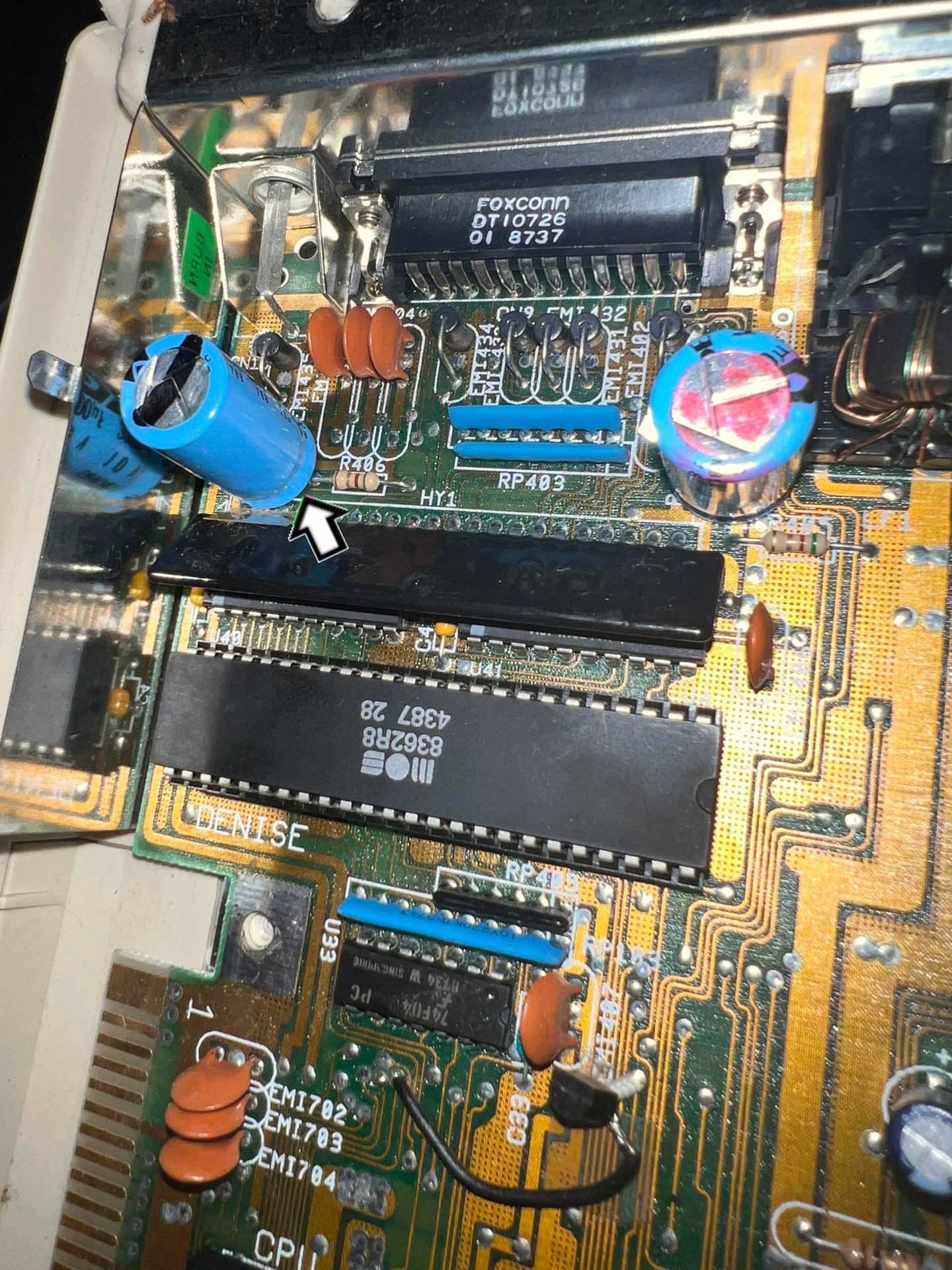
With the RF-shield out of the way the mainboard is revealed. There is some dust, but it looks to be in very good condition. I now see that this a REV 5 mainboard. Also, I can now see what is causing the rattling sound. A piece of the broken casing is found just below the GARY chip (see arrow).
Now the internal Gotek is removed. This is done by first removing the three screws at the bottom. Note that the two screws (right pointing arrows) holds the two standoffs.
The three screws at the top of the Gotek are then removed. The power- and data cable are disconnected from the mainboard and the "drive" is lifted away. Now the whole mainboard is revealed - looks great!
To free the bottom cover the mainboard is simply lifted away. Finally the 12 hex screws are removed from the back of the bottom shield (see pictures below). This releases the PCB mainboard.

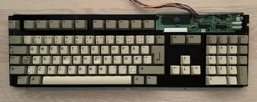
Keyboard
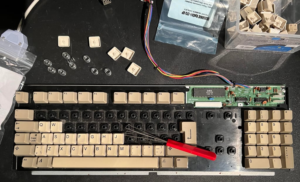
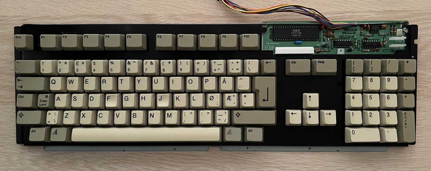
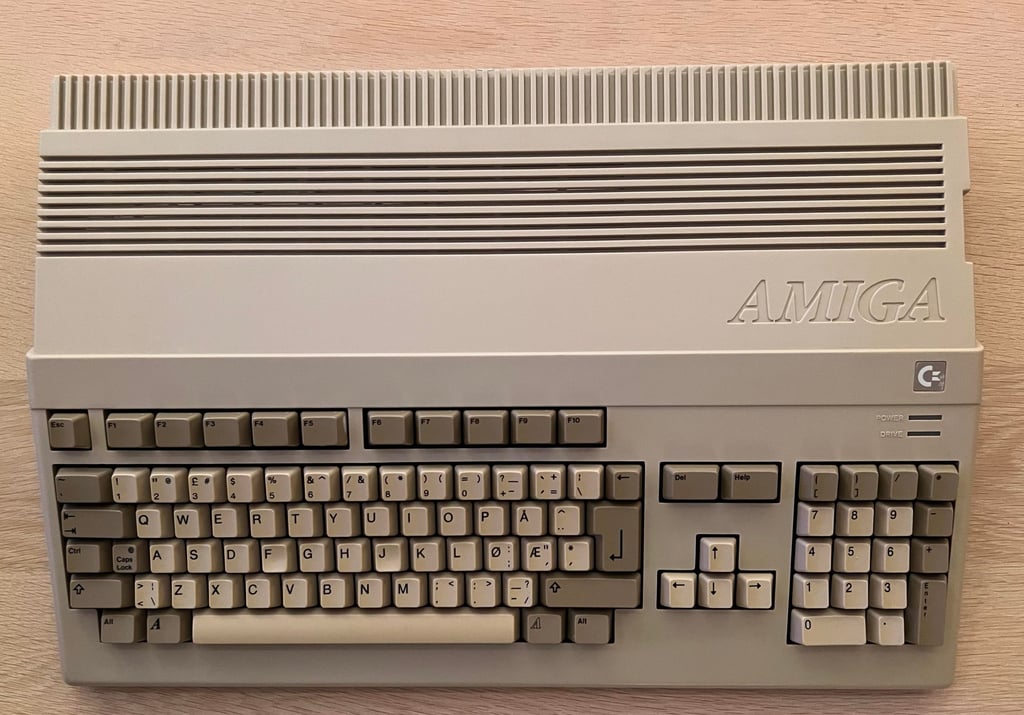
The keyboard seems to be in good condition. It is a bit dirty (I have seen much worse) and not much yellowed. This is the Norwegian version of the keyboard with the "Æ", "Ø" and "Å" keys.
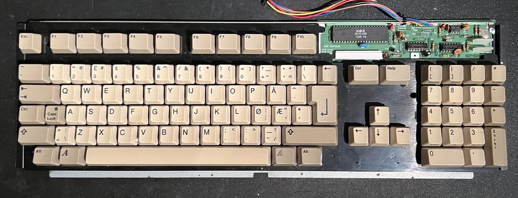
All the keycaps are removed to be cleaned. It is wise to use a special keycap remover for this task to avoid damage on the plungers or the keycap itself. Note that there is a spring beneath each key, and that beneath the spacebar there are two smaller springs in addition to the normal spring.

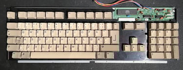
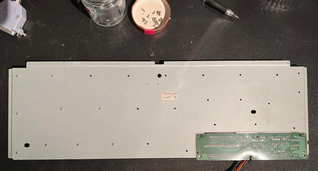
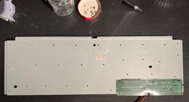
The keycaps are placed in a bowl of mild soap for 24 hours. Meanwhile the metal backplate is removed - note that there are four special screws holding the keyboard PCB so it is good practice to place these in a separate plastic bag.
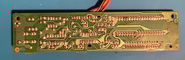
Inside the keyboard there is a membrane with carbon pads (Mitsumi A-500(E) 56 A619B). These membrane are quite notorious for failing due to corrosion (which is very hard to see and find), but hopefully this on is in working condition. The membrane is cleaned only with some distilled water to be safe.
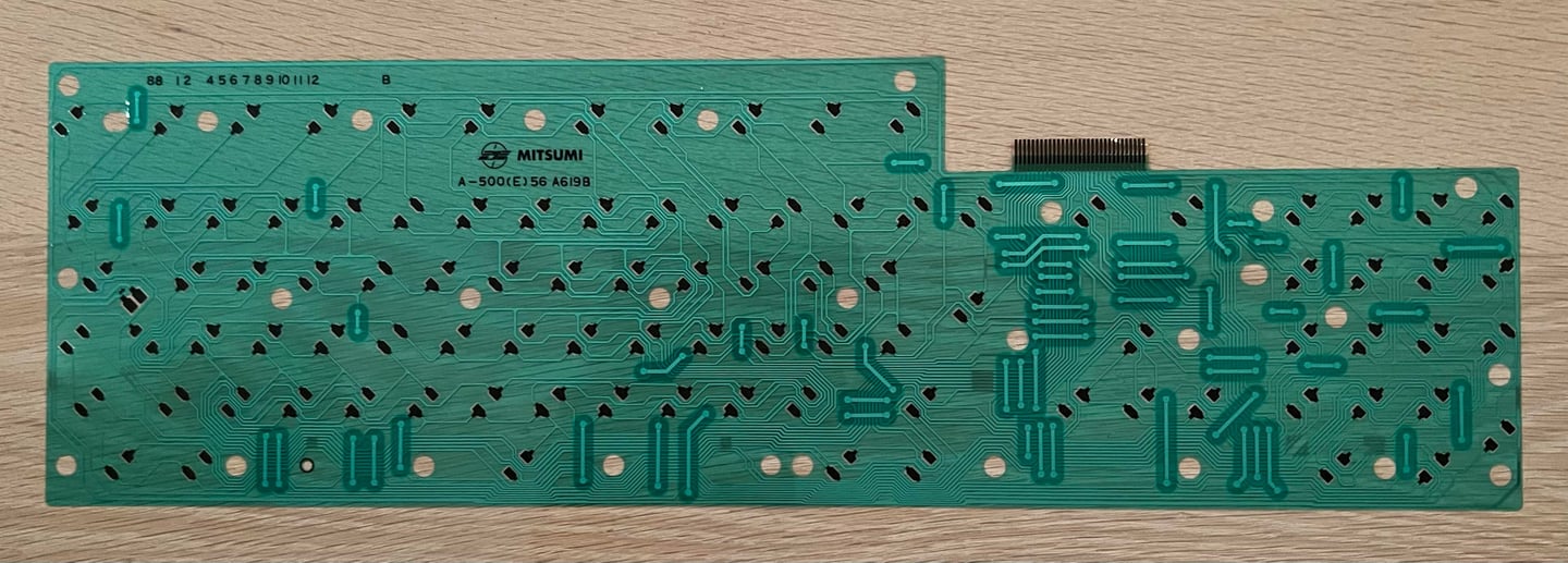

Both sides of the Mitsumi keyboard PCB is checked and cleaned. It looks to be in very good condition.
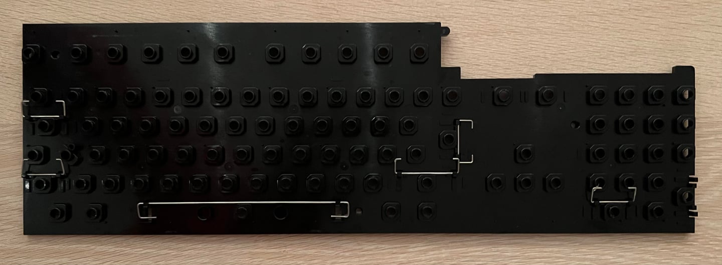
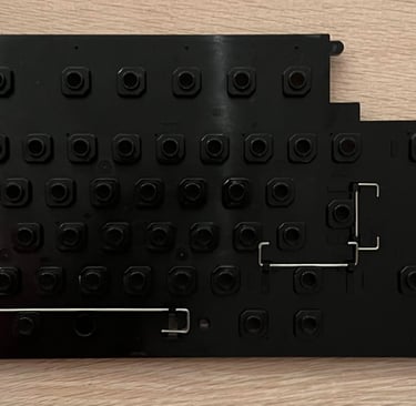
The plastic holding all the plungers is cleaned throughly with soap and water. There is a lot of grease on this, but the end result is very good. Look as new?
After cleaning the keyboard is assembled. It looks very nice!
Exterior casing
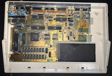
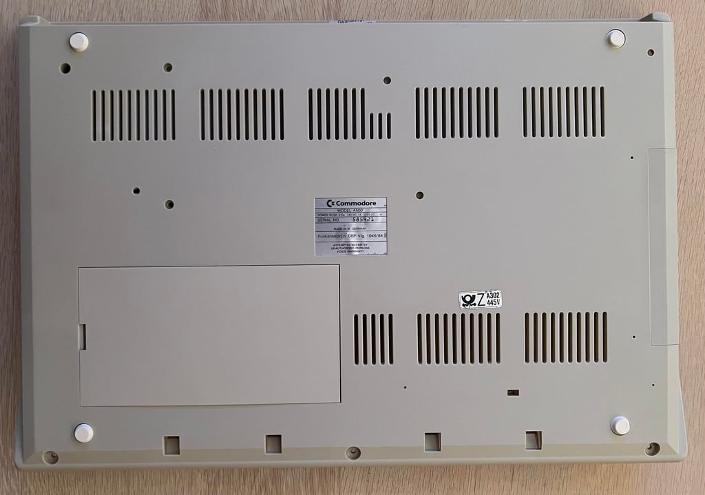
As mentioned the casing is broken on this Amiga 500 unfortunately. But there is hope! Another Amiga 500 with serial number 585421 is broken inside, but has a very nice casing. So a switch will be perfect!
The story so far
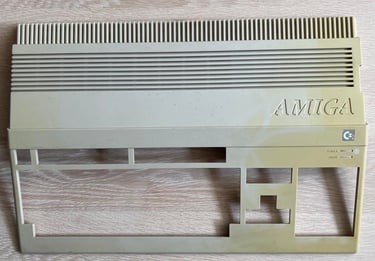
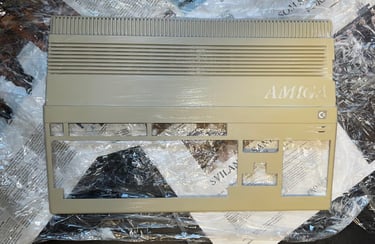
The casing on the Amiga 500 (Ser.No. 585421) was not broken, but was very discoloured on the right side. See pictures below. But even if the casing was discoloured it was complete and without any severe damage.

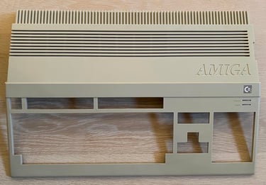
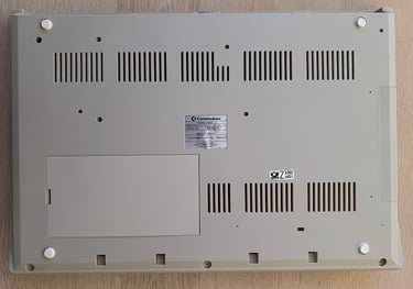
During the summer of 2023 the casing has been placed outside in direct sunlight for several days. And the result is quite good. See picture below.

No rest for the wicked
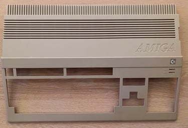
Even if the top- and bottom casing looks quite good after sunbrighting I will not stop there. I will try to give it the last "push" with traditional retrobrighting using 12 % hydroperoxide cream. The casing is so big that I need to retrobright the casing in two stages; one for the bottom and for for the top.
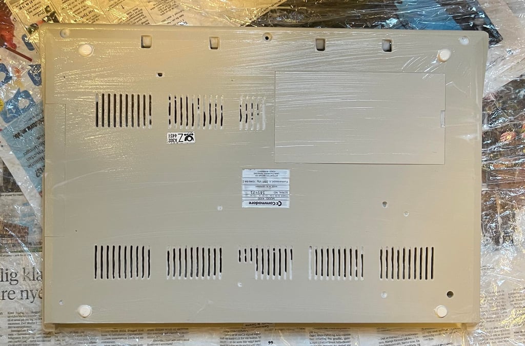

The bottom cover looks very good I think after retrobright. See pictures below.
And finally the top cover.


Mainboard

Visual inspection
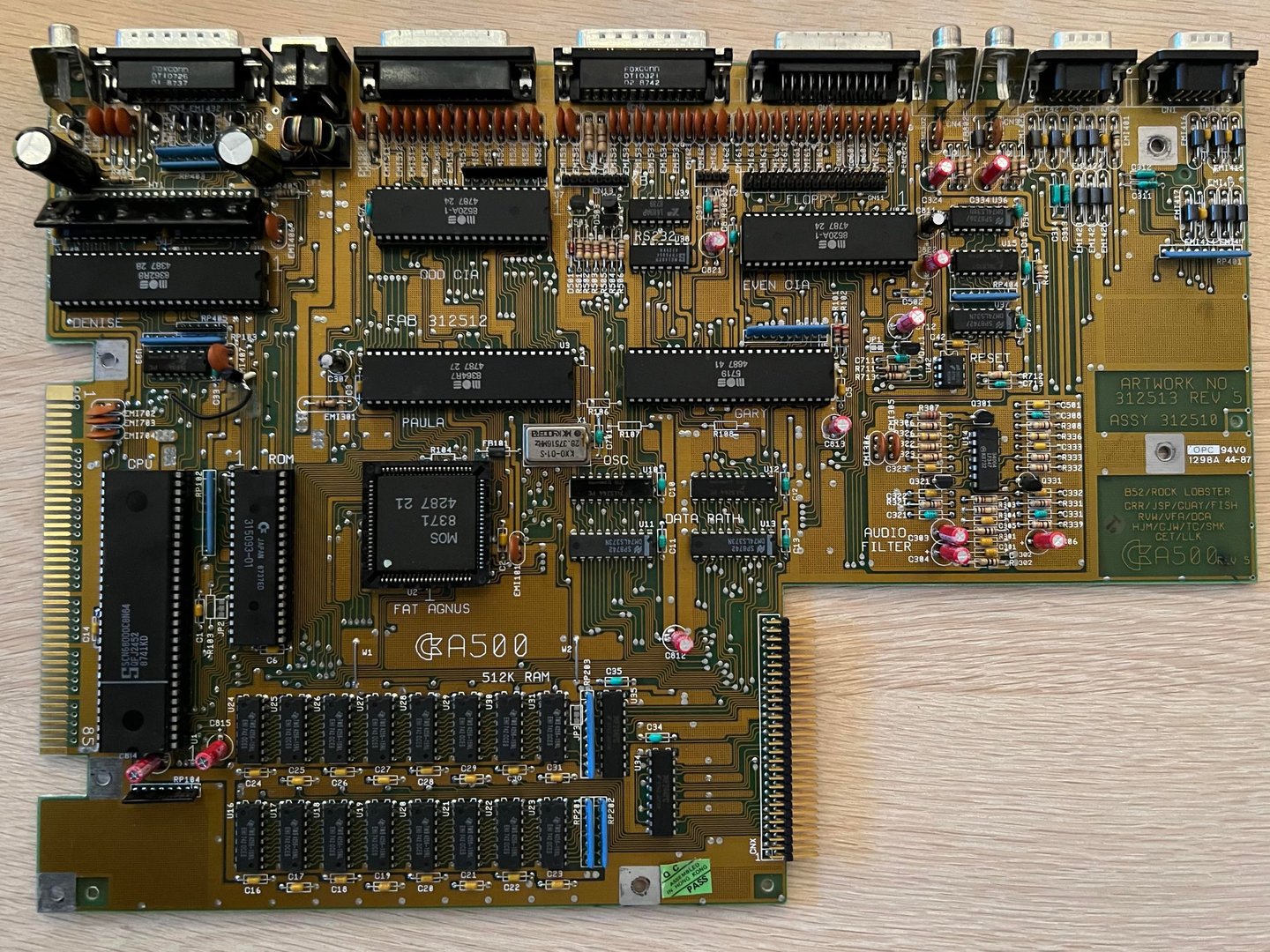
This is a Assy 312510/Artwork 312513/Rev 5 mainboard - a very common (the most?) revision of the famous Amiga 500. The board looks to be in a very good condition. I can not see any sign of damage. There is a bodge wire from the transistor close to the 7404 IC, but I think this is from factory. The leftmost 3300 uF capacitor is a bit loose. I am not sure if this is because the capacitor is starting to deteriorate, or if the capacitor is poorly soldered
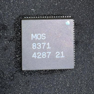
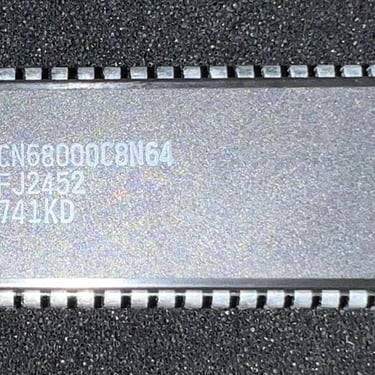
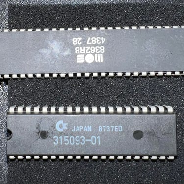
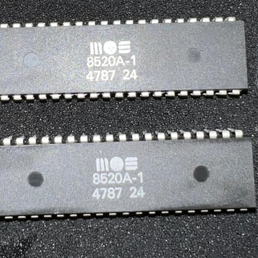
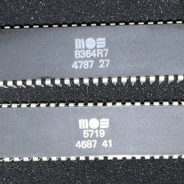
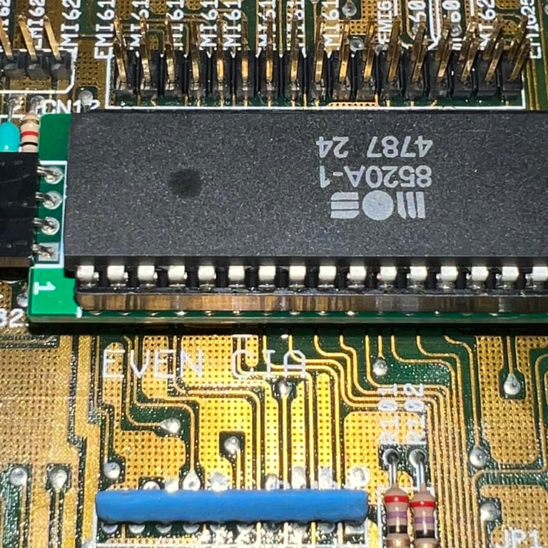
In the table below all the major custom IC found on the mainboard is listed. As can be seen from the table the custom MOS chips were produced between week 37 to 47 in the year 1987. So this machine is now 36 years old (september 2023) - and if I remember correctly 1987 was the first year the the Amiga 500 were produced I think.
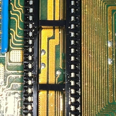
Cleaning the chips and sockets
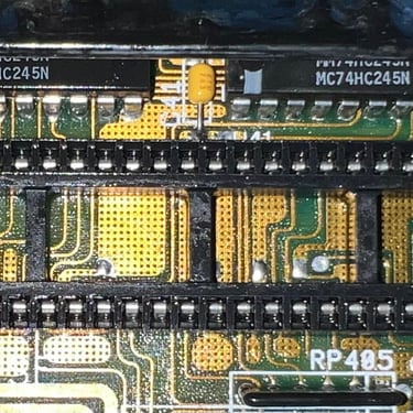
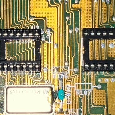
A quite common fault on A500 is that custom chips loose connectivity due to oxidized sockets - or that the chips gradually are lifted away from the single leaf sockets. Therefore all the custom chips are removed from their sockets. And all chips are cleaned individually with glass fibre pen and isopropanol. Also, all the sockets are cleaned thoroughly with isopropanol and a tooth brush.
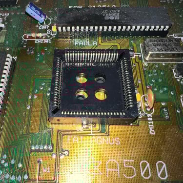
NOTE#1: Never attempt to remove the Fat Agnus 8371 chip without a PLCC extractor. If you use a screwdriver to pry it loose you risk (with a very high probability) to break either the PLCC socket or the chip.
NOTE#2: I recommend using a chip lifter when removing the MOS custom chips (except Fat Agnus). You can also use a small flat screwdriver, but with a chip lifter you get a much more gentle way of removing them.
Below are some pictures from the cleaning process.
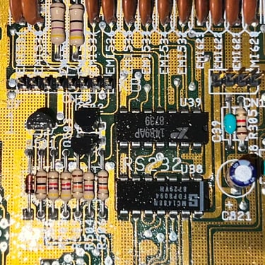
Replacing the electrolytic capacitors
All of the 16 electrolytic capacitors on the mainboard are replaced with new quality brands. The old capacitors were over 36 years old and have done their duty in this machine. No trace or pad were damaged during the desoldering/soldering process.

Disk drive
As previously mentioned this A500 came with an internal Gotek drive installed. The owner of the machine wanted to have this replaced with an original Amiga floppy drive - a refurbished Chinon FB354 drive will be used (a detailed description of the refurbishment of the drive can be seen by clicking on the link).
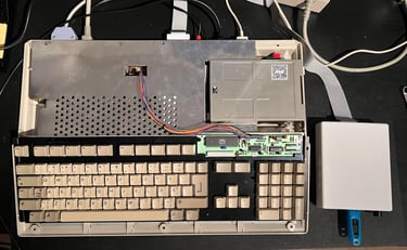
The disk drive is installed as seen in the picture below.
512 kB RAM expansion
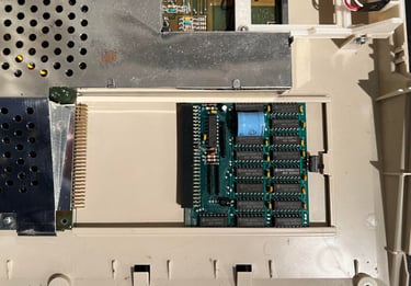
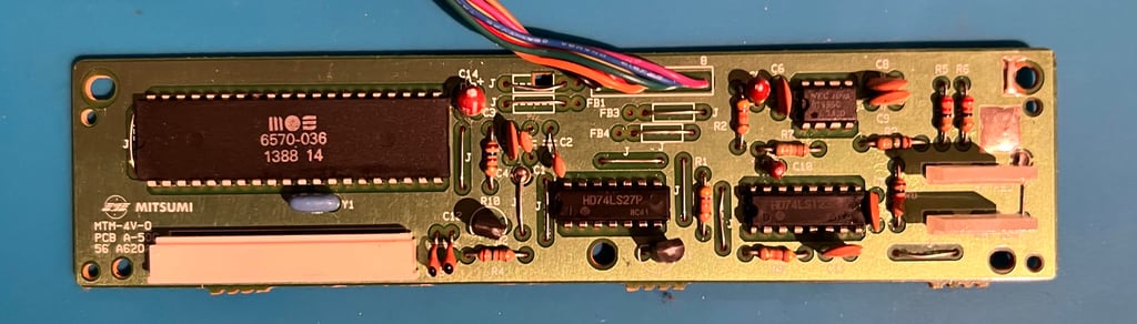
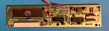
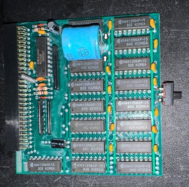
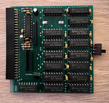
Following this machine is a 512 kB RAM expansion. At time of writing I do not know if it works, but I have high hopes. It looks quite good even if there is a - lo and behold - battery(!) There is really not much leakage, but there are some signs of corrosion (see arrows) so the battery needs to be removed. Otherwise there is a high risk that the battery can start leaking and damage the PCB severly.
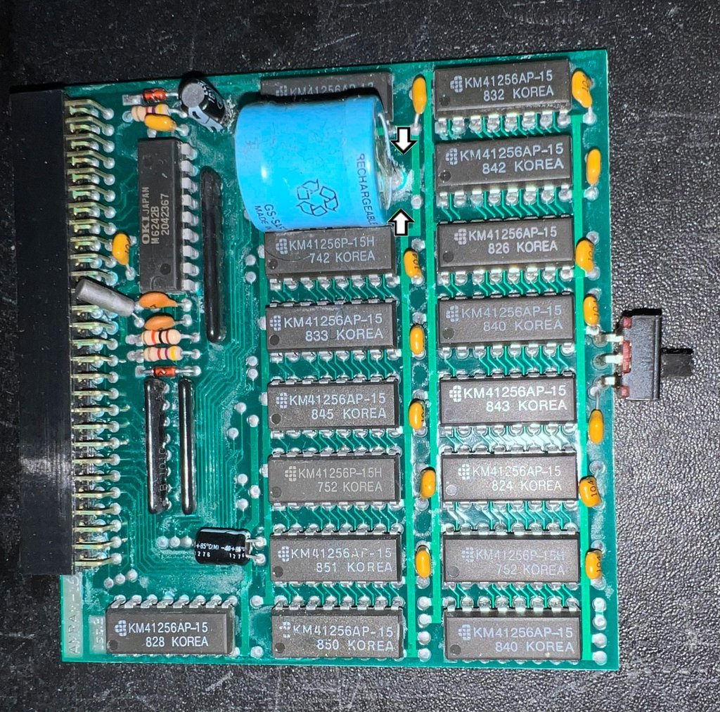
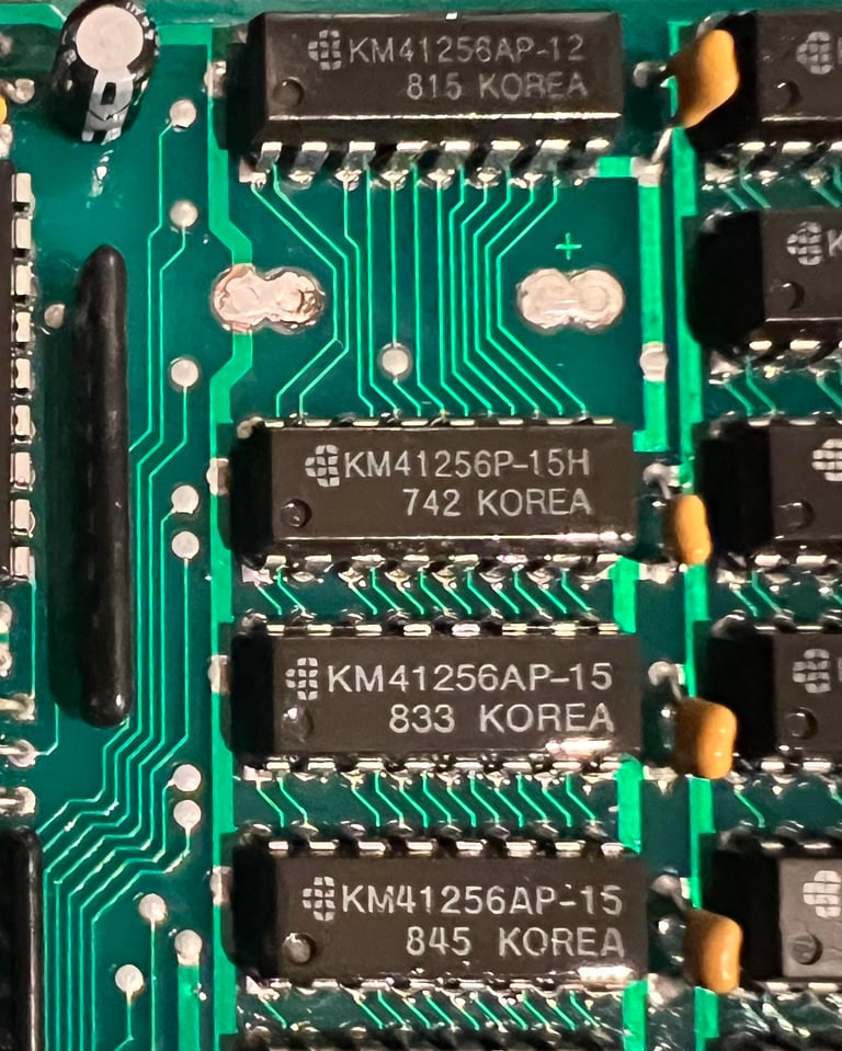
The expansion card consists of 16 256Kbit dynamic RAM chips. All the chips looks to be in good condition, but I notice that the bottom number varies between 752 to 851. Could this be some kind of date stamp? Also, there is a switch on the PCB to toggle the RAM expansion on/off. There are two electrolytic capacitors that might need changing, but they look quite ok so I leave them for now.
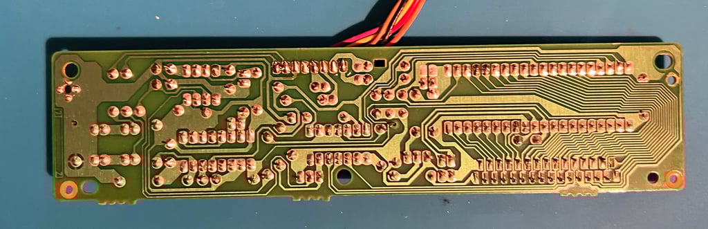
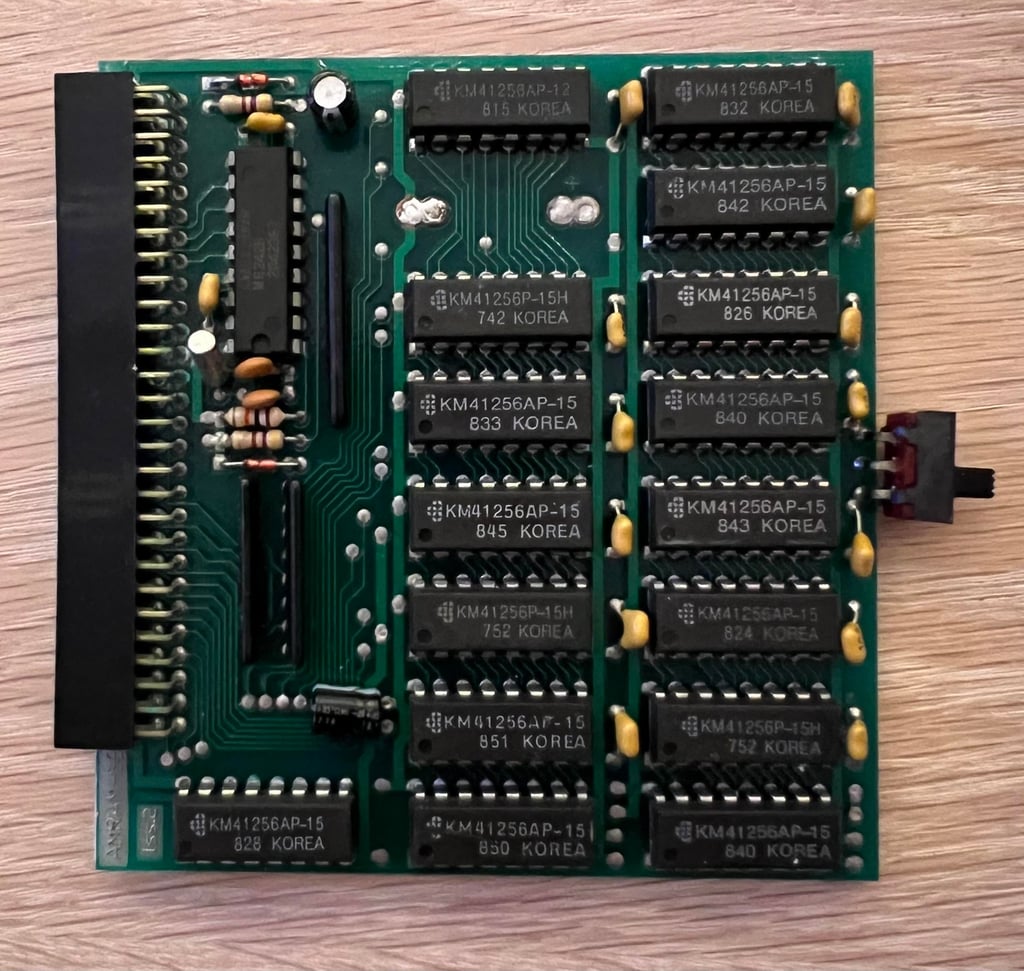
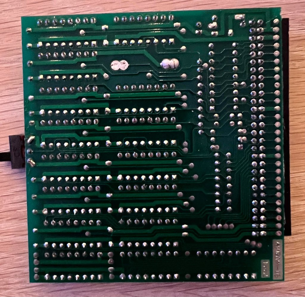
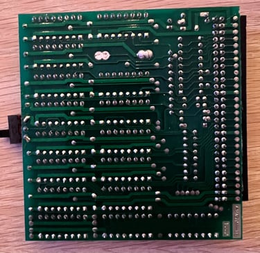
First the battery is removed and all the corrosion is removed with a sharp metal pin. Finally, the area is cleaned and the open holes are filled with fresh solder. The cleaned area is shown below.

Both sides of the PCB are cleaned thoroughly with isopropanol - see picture below.
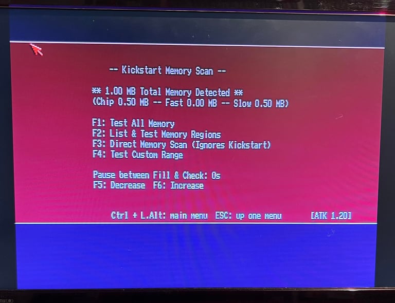
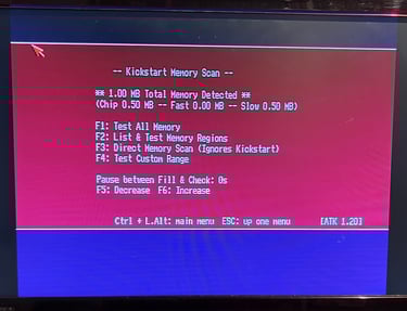
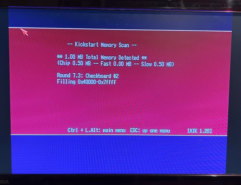
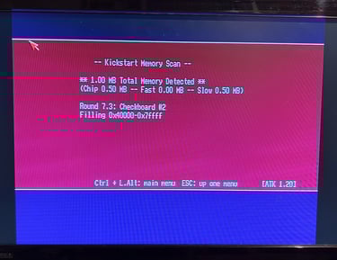
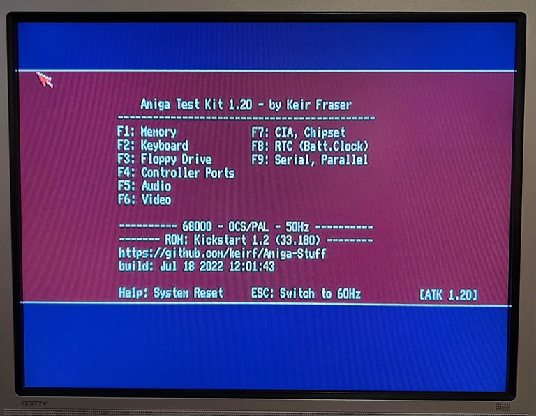
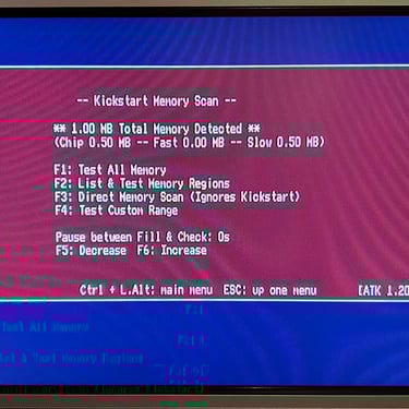
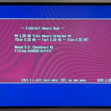
Testing the RAM card with Amiga Test Kit shows that it is both detected (0.5 MB chip + 0.5 MB fast) and that no errors are detected.
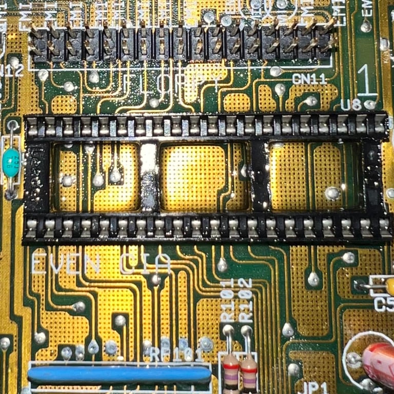
DF0/DF1 floppy drive boot selector
This Amiga 500 will use an external Gotek drive in addition to have an original Amiga floppy drive. To be able to use the external Gotek drive as the "primary floppy drive" a DF0/DF1 switch is installed. With this switch the user can select which floppy drive to boot from; either the internal floppy or the external Gotek.
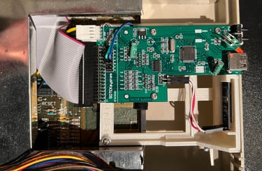
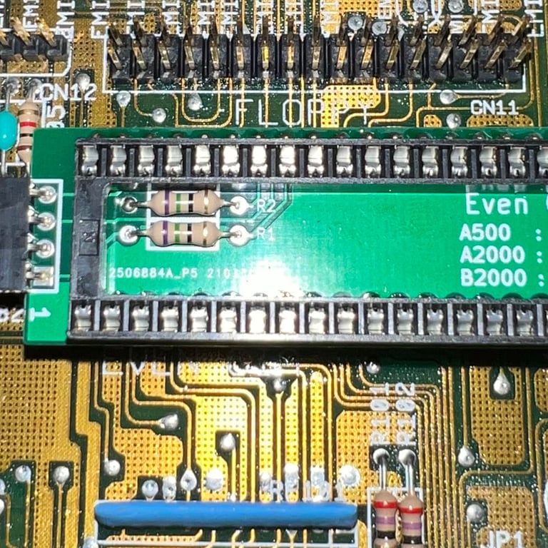
The DF0/DF1 switch is supplied from Amiga Kit Store. As can be seen from the picture below the kit consists of a small boot selector PCB and a an extension cable and switch.
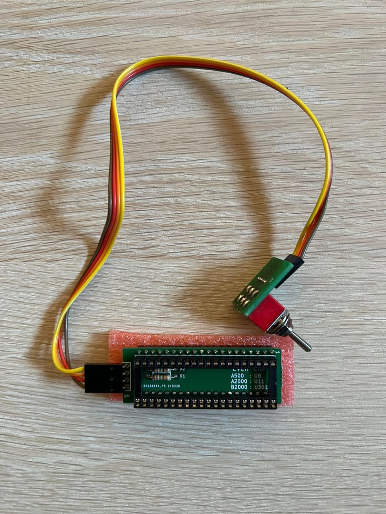

To install the DF0/DF1 floppy boot selector the EVEN CIA is removed. The boot selector is placed in the EVEN CIA socket, and then finally the CIA chip itself is placed in the boot selector PCB socket. See image gallery below.
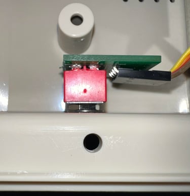
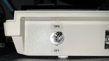
The DF0/DF1 switch is mounted on the back of the casing. There is some free space next to PORT # 1 (mouse) which is a good place for this switch. Labels marked "DF0" and "DF1" are placed next to the switch to make it easier to remember the boot options.


External Gotek drive
With an external Gotek drive and a DF0/DF1 you can keep the Amiga "as original as possible" - and at the same time enjoy the ease of having all of your great software on a simple USB stick instead of old floppies.
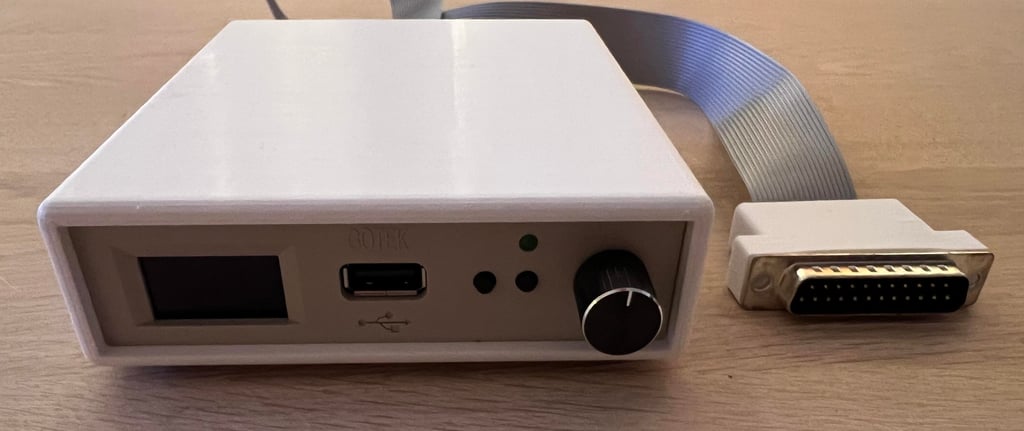
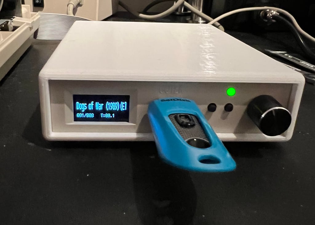
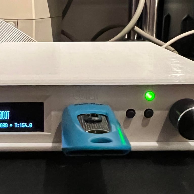
The Gotek package is pictured below. Note that this Gotek drive also has a 3D printed casing which looks quite nice.

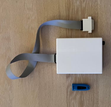
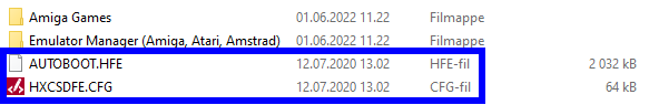
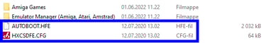
The USB stick is pre-configured with a few Amiga games and two important files which are required for the Gotek to boot. You can place your demos/games everywhere you want, but the two config files (see blue square in picture below) need to be in the root folder on the USB stick.
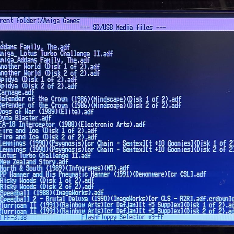
Some games are downloaded for testing purposes (https://tosec.ikod.se/ - note that I do not take any responsibility for any legal rights) and placed on the USB stick. To access the Gotek boot menu the selector needs to be set to "AUTOBOOT" and then reboot the Amiga.
Below are some pictures from testing the external Gotek (DF0/DF1 selector set to "DF1").


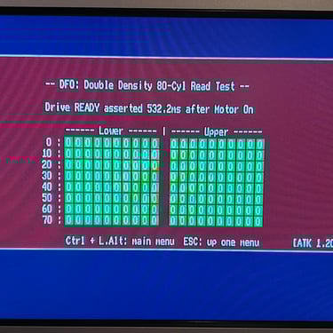
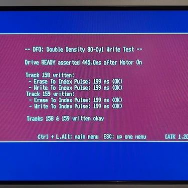
Testing
Now it is time for testing the whole machine. All parts such as keyboard, RAM expansion, keyboard and disk drive have been tested in isolation, but now I will try to test "everything". How? Well, I basically to this in two stages:
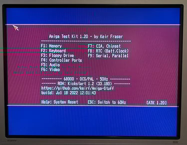
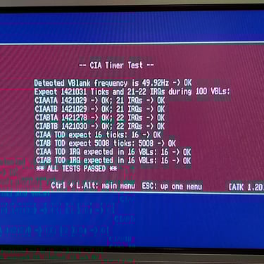
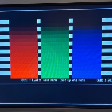
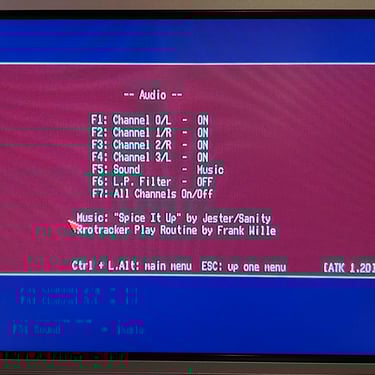
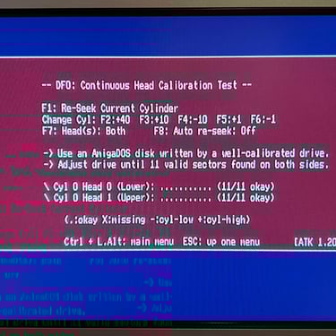
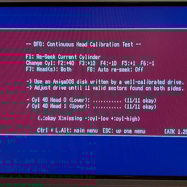
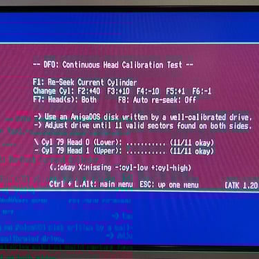
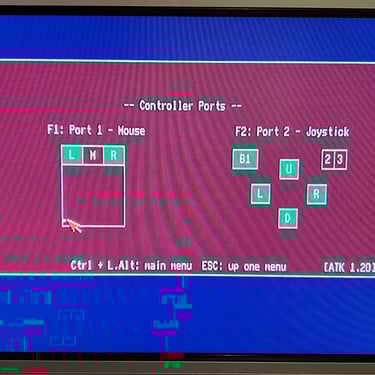
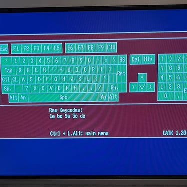
Formal testing with the Amiga Test Kit 1.20 (ATK). This will test most of the basic parts such as memory, floppy drive, video, audio, CIA, mouse, joystick and keyboard.
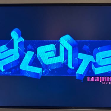
"Real usage" testing. I will basically use the machine playing games, watching and listening to demos and use the machine in regulator operation. This will detect flaws not easily detected with the ATK 1.20.
Below is a gallery from the final testing.
Verifiying the audio signal level
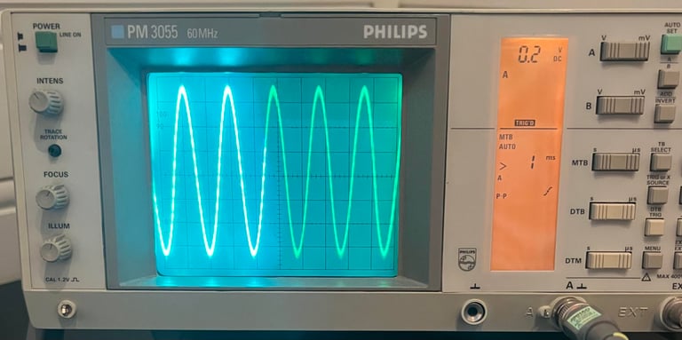
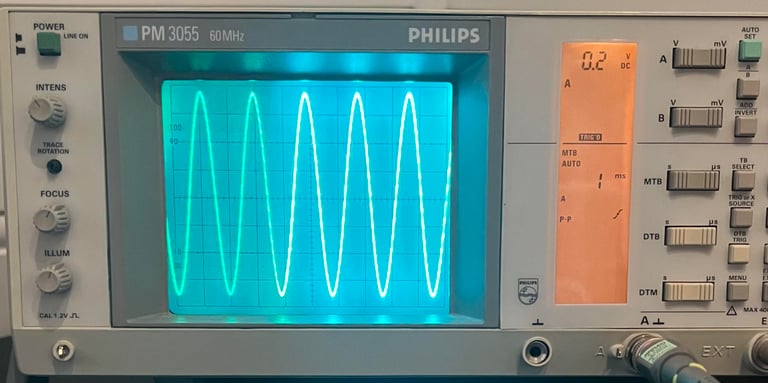
While testing I notice that the audio level on my TV is low. It turns out that my TV is now broken (oh no...), but to make sure that the audio level is ok from the Amiga 500 the oscilloscope is used. Below are pictures from the audio output (both right- and left channel) measured at the RCA connectors. The signal used is a 500 Hz sine wave from Amiga Test Kit. As can be seen the signal is a clean sine wave with an amplitude of just below 0.8 V.

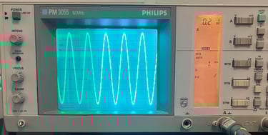
The audio signal is also measured at C324 and C334 and is ok. Note that at these positions the voltage level is DC-biased in the range of 0 - 2 V since these are polarized capacitors. See video below (note that the audio is not very good - both this is due to my crappy TV and another TV with the news in the background ).

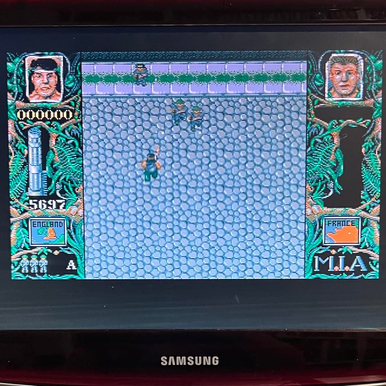
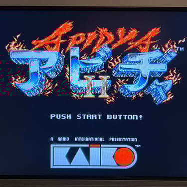
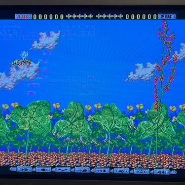
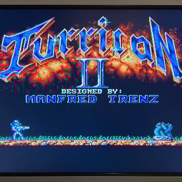
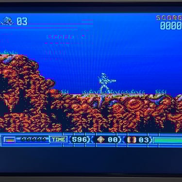
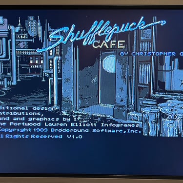
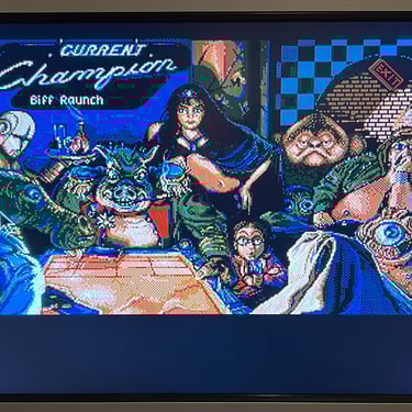
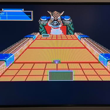
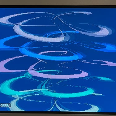
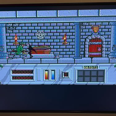
Testing games and demos - with internal floppy and external Gotek
Below is a gallery of pictures from the testing of the A500. Both the internal floppy (with old disks) and external Gotek are used during testing.


Final result
"A picture worth a thousand words"
Below is a collection of the final result from the refurbishment of this Amiga 500. Hope you like it! Click to enlarge!


Banner picture credits: Ajne01