

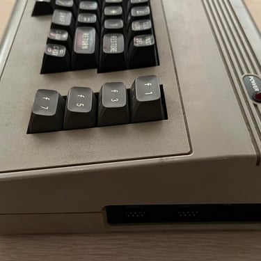
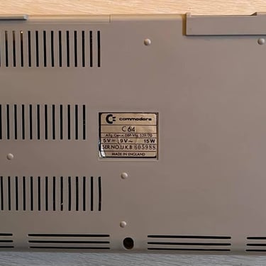
C64 Breadbin
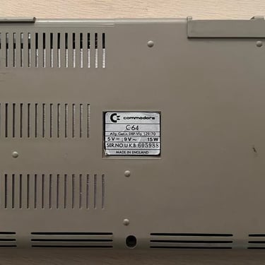
Ser. No. 605988
Assy 250407
Artwork 251137 (REV B)
Refurbishment plan
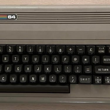
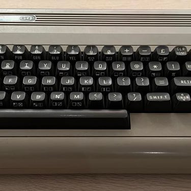
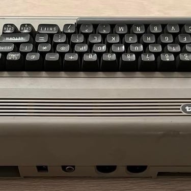
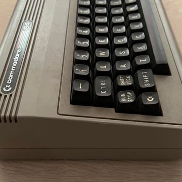
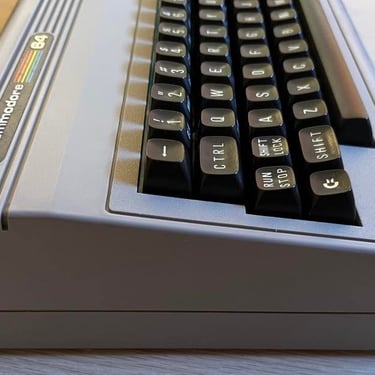
From the outside this C64 breadbin looks quite nice. I can´t see any damage to it from the outside. It´s a bit dirty but otherwise looks OK.
The refurbishment plan for this C64 breadbin (some of them in parallell):
- Clean and restore the keyboard
- Clean and remove stains from the chassis
- Refurbish main board (cleaning, checking, repairing, replacing capacitors and voltage regulators etc.)
- Recap RF-modulator
- Verify operation by testing
Below you will find some pictures before I begin the refurbishment (click to enlarge). Doesn´t look bad at all! This can be a fun project!
Keyboard
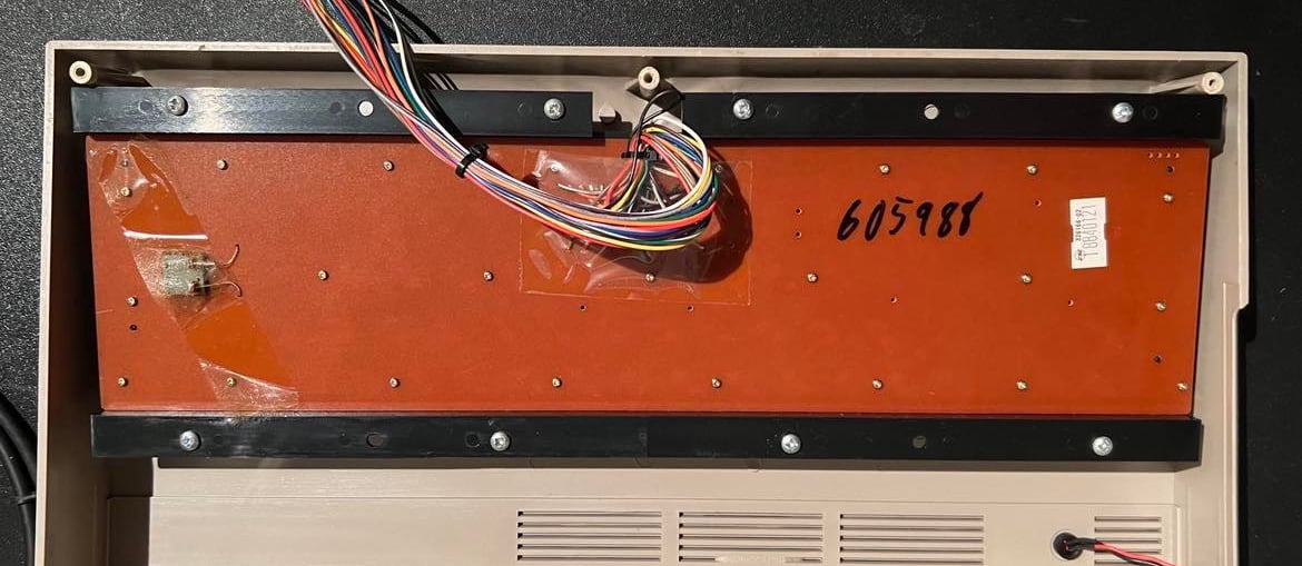
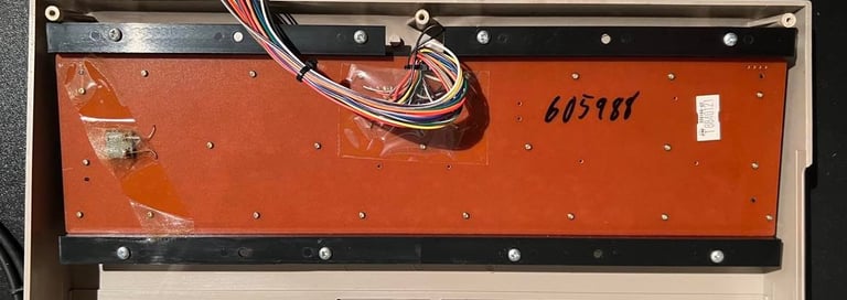
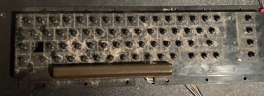
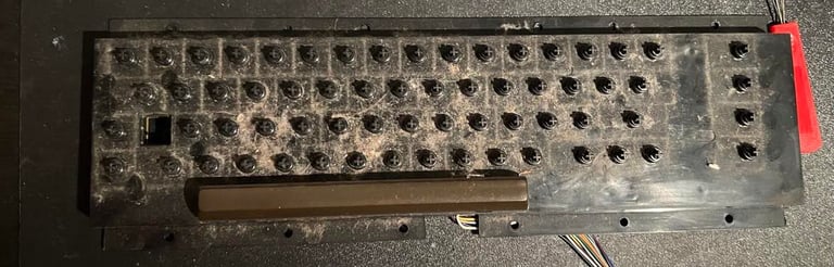
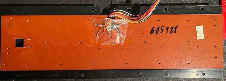
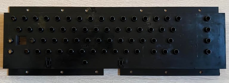
To get the keyboard out of the top cover the eight screws are removed. These screws holds the keyboard tight to the top cover - but it´s important to be careful when the screws are removed so that the plastic stands don´t break. The picture below shows the keyboard before disassembly. Notice that the serial of this C64 is written on the backplate of the keyboard. This is the first time I´ve seen - I wonder why?
When the keyboard is removed from the chassis the first thing to do is to remove the SHIFT-LOCK key. And here I´ve seen people struggling with this which is completely unnecessary because it´s very easy. So here´s the simple how-to:
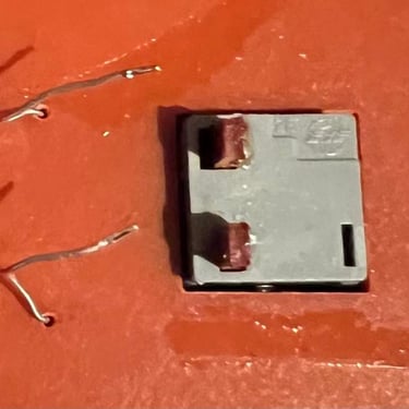
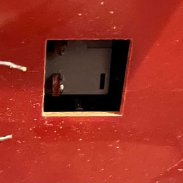
Desolder the two wires connecting the SHIFT-LOCK from the backside
From the backside of the keyboard push firmly forward - and the key will "snap" out. I use ONLY a small force and NO tools such as screw drivers.
When the keyboard is removed from the chassis the first thing to do is to remove the SHIFT-LOCK key. And here I´ve seen people struggling with this which is completely unnecessary because it´s very easy. So here´s the simple how-to:
Desolder the two wires connecting the SHIFT-LOCK from the backside
From the backside of the keyboard push firmly forward - and the key will "snap" out. I use ONLY a small force and NO tools such as screw drivers.
Below are some pictures from the process.
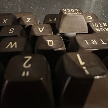
With the SHIFT-LOCK out of the way it´s time to remove the rest of the keys. I use a simple key puller to do this (see My Tools).

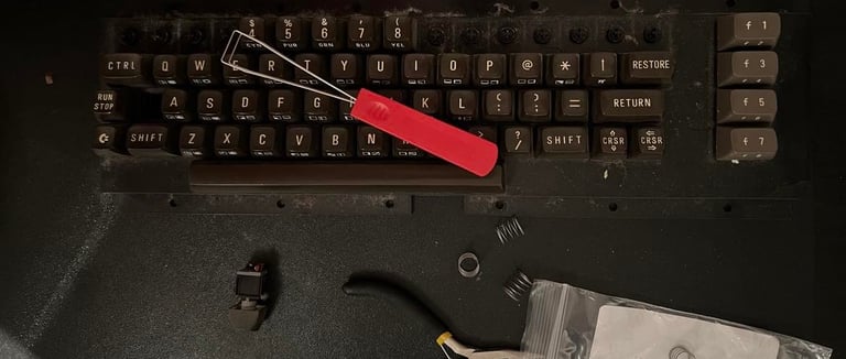
When all keys are removed it´s time to remove the space bar. Why is this so special? Well, the the thing is that the space bar use a different spring than the rest of the 65 keys. So a smart little advice is to keep this spring in a separate plastic bag. By the way - do you think the picture below looks really nasty? Well, it´s not looking delicious, but this is WAY BETTER than other keyboards I´ve seen. Note that when all keys are removed they are placed in luke warm (cold?) water with some mild soap for some hours.
Next step is to remove all the small screws at the back plate. None of the screws have any sign of corrosion which is good! There are 23 screws to be removed - a good advice here is to keep these in a separate plastic bag so that you don´t loose them. The plastic chassis is washed thoroughly with luke warm soap water.

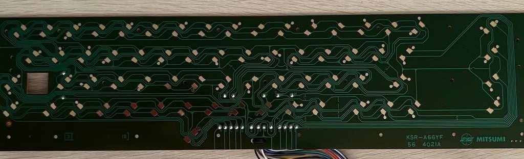
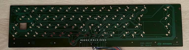
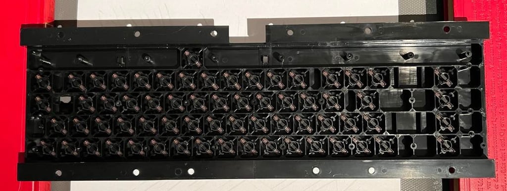
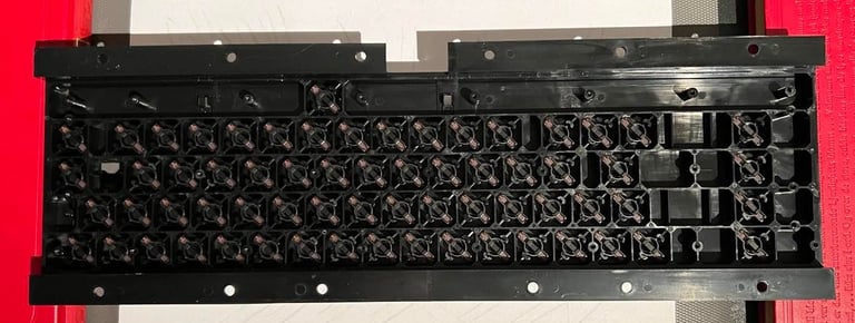
The keyboard PCB looks very nice already! I can´t see any sign of corrosion or damage. This is the classic KSR-A66YF PCB from Mitsumi. Nevertheless, I clean it properly with isopropanol. See picture below.
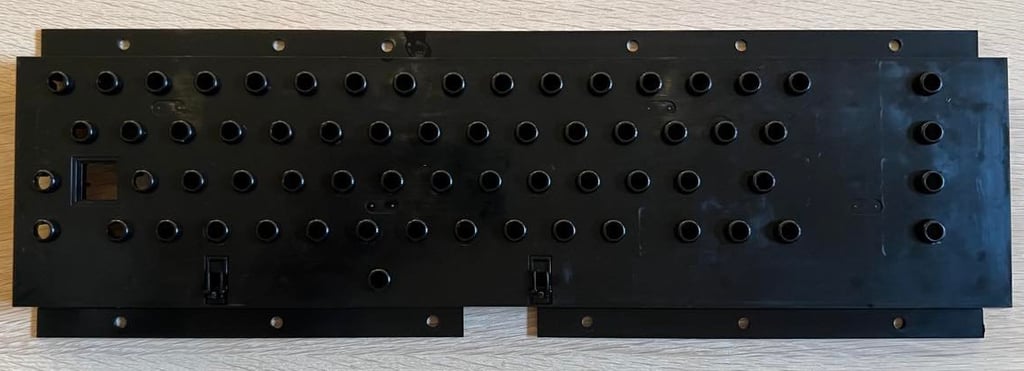
After cleaning the plastic case with nothing but soap water the result is very good. See picture below.
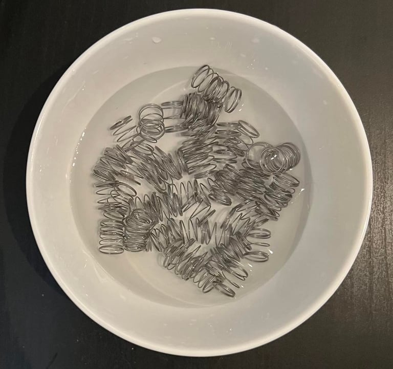
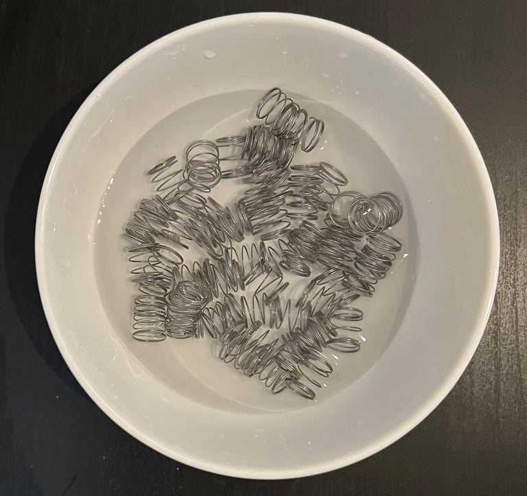
The springs looks fine without any major sign of rust. Nevertheless, I place all of the springs in a bowl of vinegar which will remove any rust.
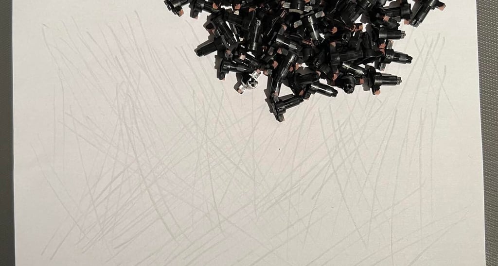
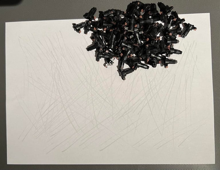
I revive the plungers by using a little trick; I gently drag the plungers over a clean sheet of paper. This will clear the carbon from dust and grease - and I find this way more gentle to the plungers than washing them with isopropanol. After this cleaning the plungers are put back and the PCB mounted.
Exterior chassis
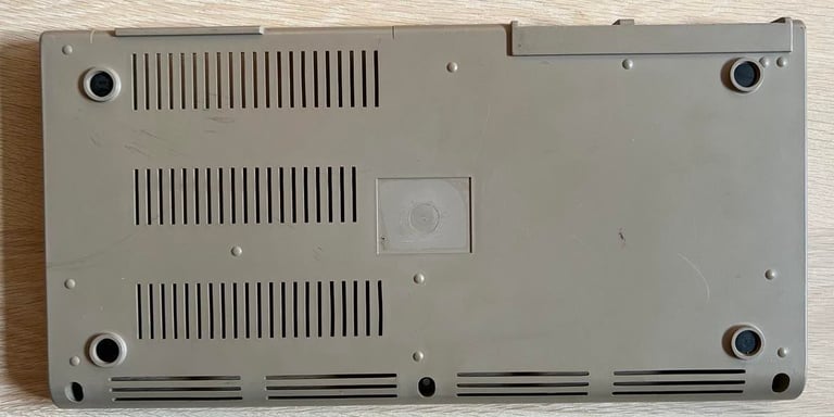
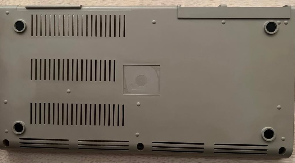
The extorior chassis consists of two main parts; the top- and bottom cover. When I got this C64 the chassis were already quite loose since the three screws were missing at the bottom (connecting the top- and bottom cover).
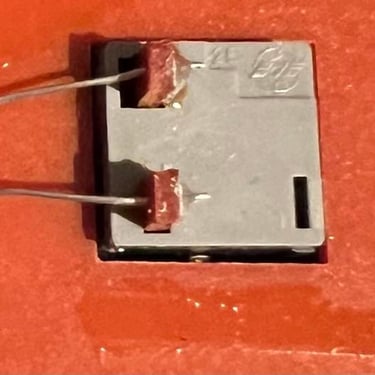
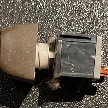
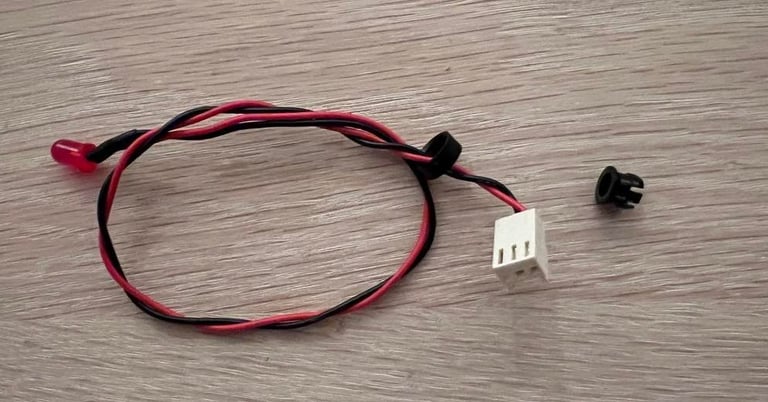
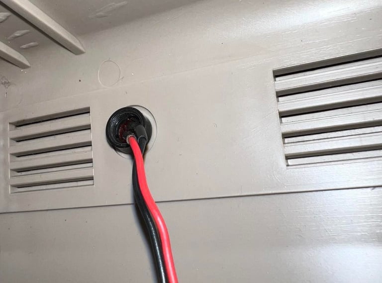
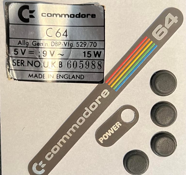
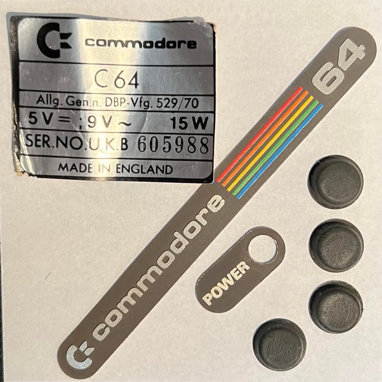
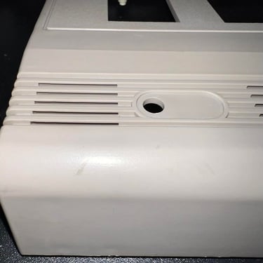
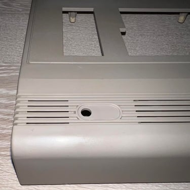
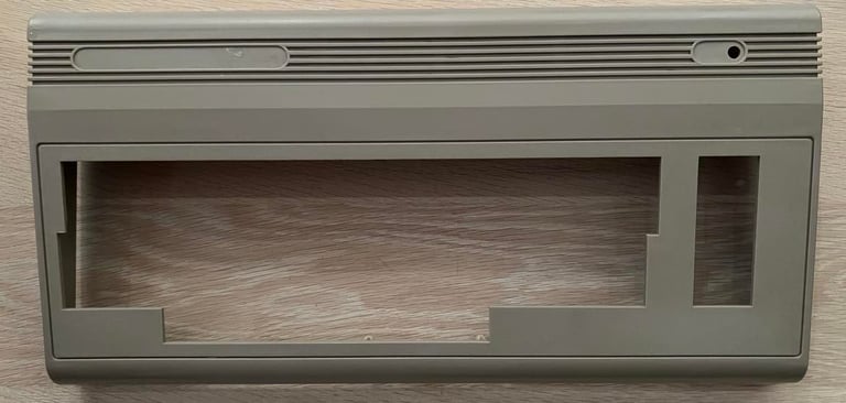
The covers needs a good cleaning. But before I clean them I will (try to) remove all badges and stickers so that they don´t get damaged during the cleaning process. Also, the red LED is removed. To remove this first remove the small circular clip from below. Then push the LED from the front to the back so that it "snaps" out. With the LED out of the way the last clip is removed. This will also make way to remove the "POWER" badge. Pictures below show the ring before it is removed and the LED when everything is removed.


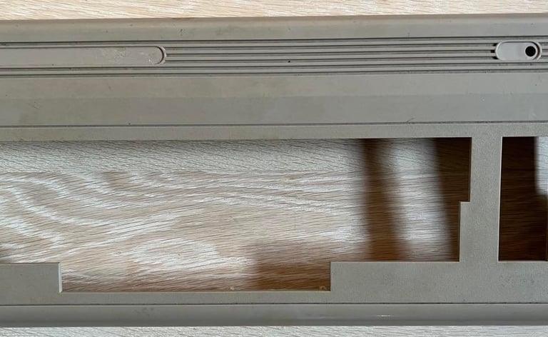
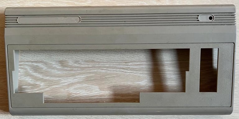
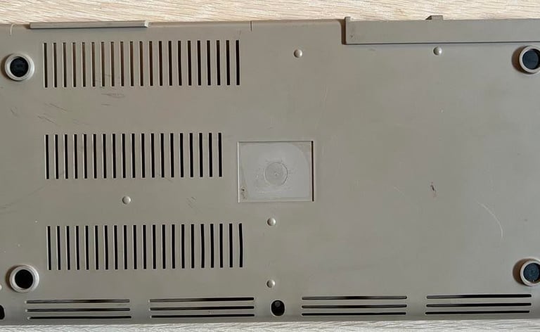
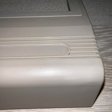
To remove the two badges in the front and the sticker on the back I apply some heat (not much!) with a hair dryer on these. And then carefully lift them off with a small paperknife. This process takes a while and it is important that you don´t rush it. If you apply too much heat the plastic casing can take damage, and if you pry the badges off too fast you risk bending the metal. Also, I remove the four rubber feet at the bottom. I don´t think this is strictly required, but I do it just to make sure they are not damaged in the cleaning or retrobrighting process. Below are pictures of the top- and bottom cover before cleaning and also the badges/stickers/rubber feets.
First part of the cleaning process is to wash the top- and bottom cover with lukewarm soap water. This will remove most of the dust and fat. But the stains will require some more work. To get the stains away I use a combination of isopropanol, baking soda and glass cleaning spray. Below are some examples where stains are removed with baking soda - very effective.
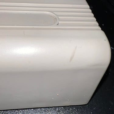
The result of cleaning is quite good I think. Most of the stains are gone and looks nice! I would probably retrobright it later, but as for now this i a good result.
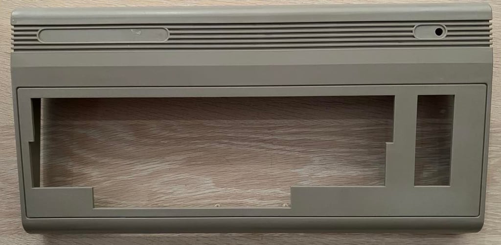
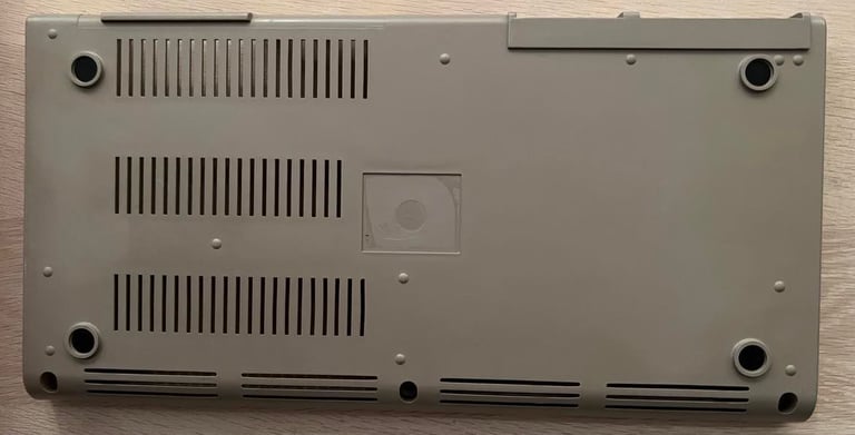
Top- and bottom cover and the keys in addition are retrobrighted for about 7 hours. I use 12 % hydrogenperoxide cream for this in combination with a UV-lamp. After the retrobrighting all the parts are cleaned with mild soap and then polished with glass cleaning spray. As a final operation on the chassis the stickers are put back. I use double-sided tape for this.
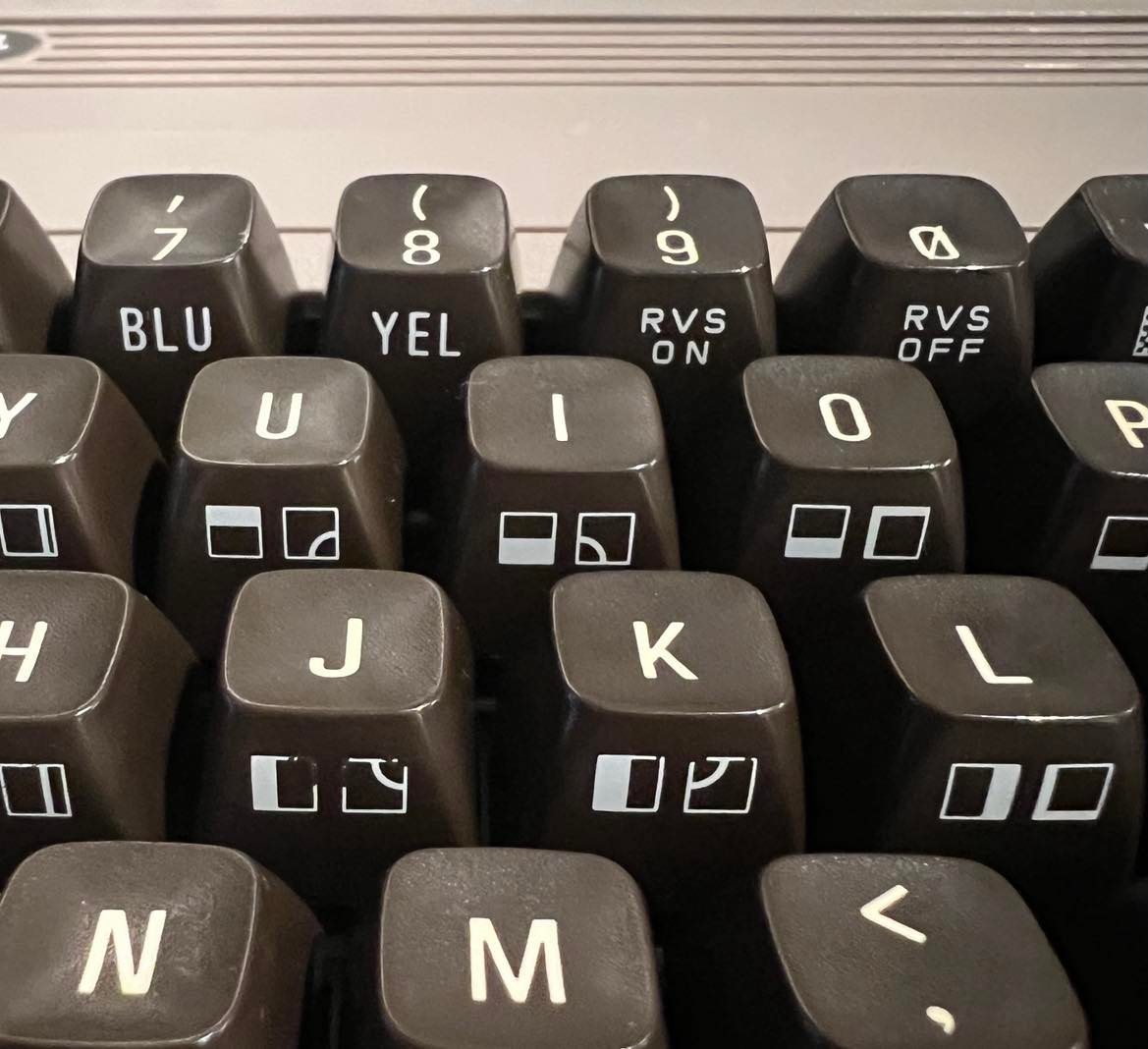
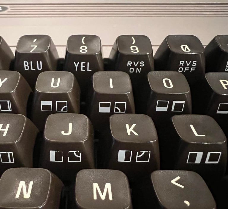
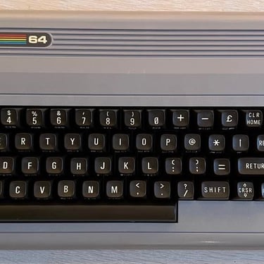
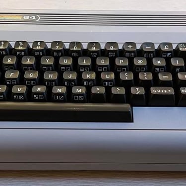
Below is a picture of the top cover after this operation - the keys are also retrobrighted but they will probably not be much whiter than this.
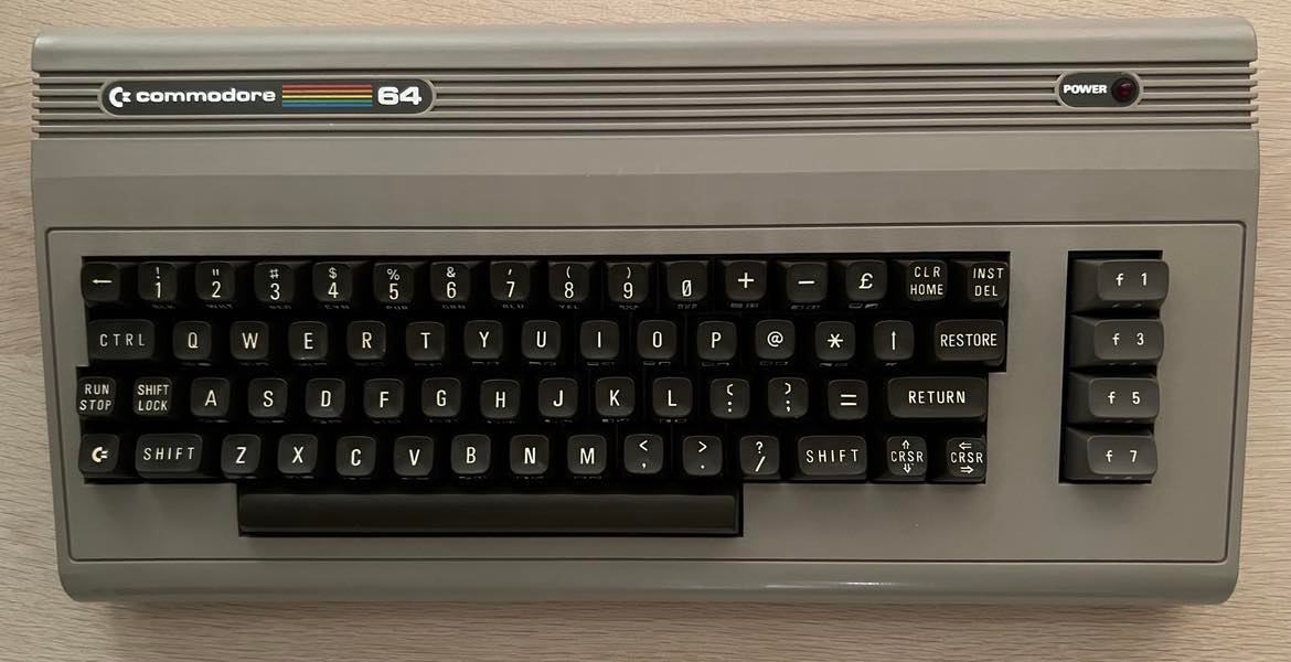

I notice that some of the print is missing in front of the "J" and "K" key. I think this could be due to the retrobright process, but I´m not entirely sure.
Main board
I start the main board refurbishment process by a visual inspection and note the following:
There is quite some dust and fat on the board. But this is normal and can be washed off.
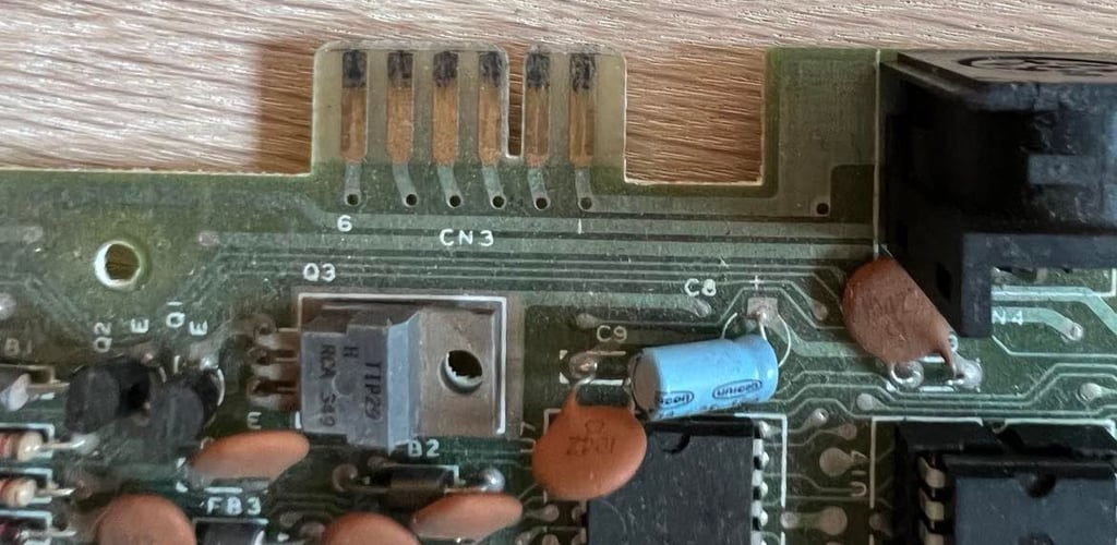
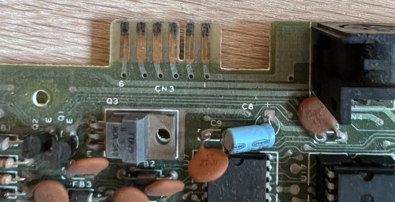
The datasette port have some dark markings due to extensive usage I assume. This should be ok to refurbish, but it´s important that these are cleaned in order for the datasette to operate properly.
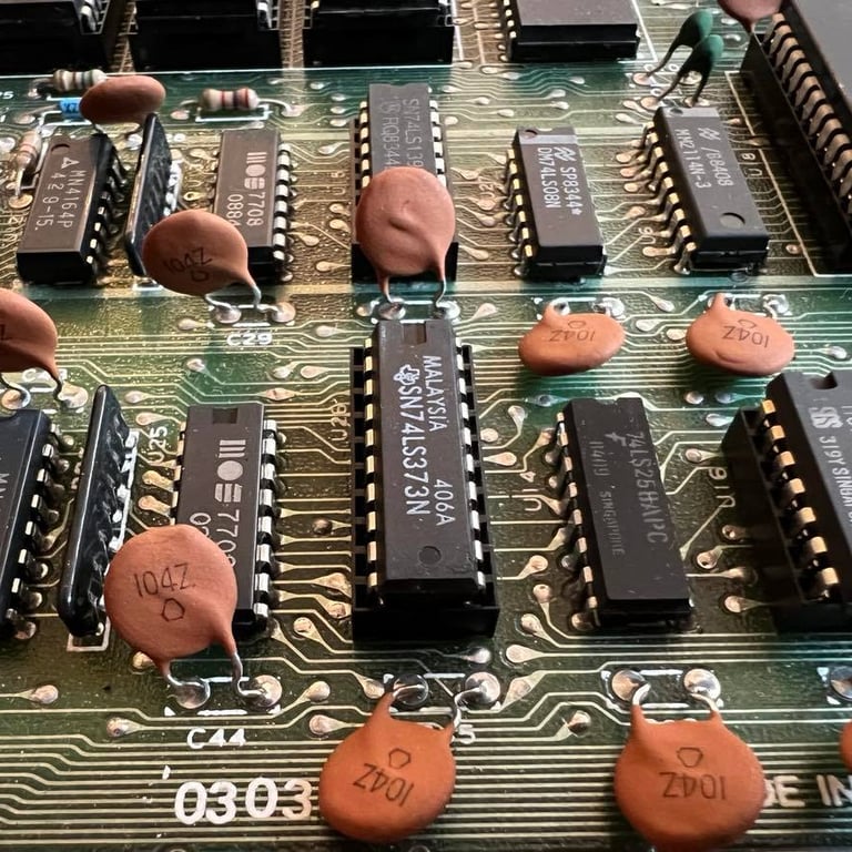
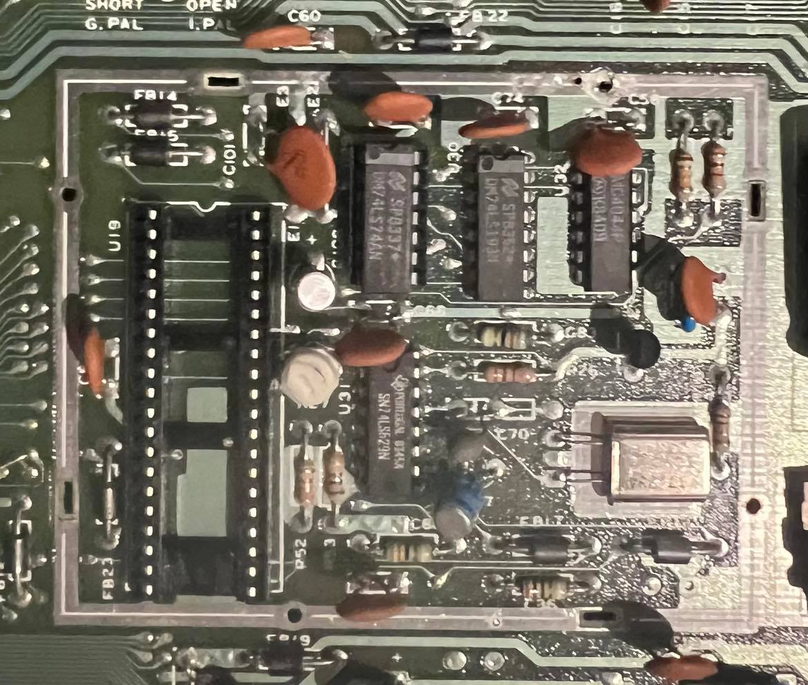
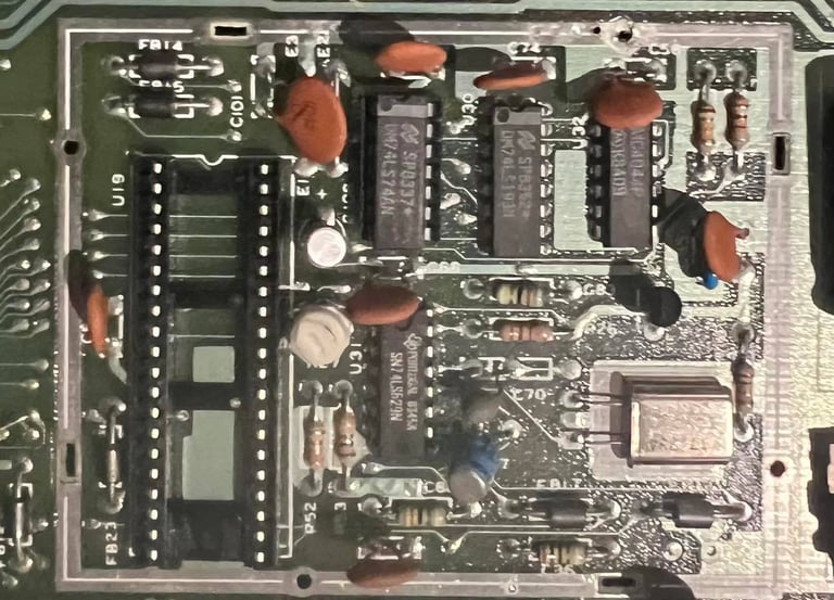
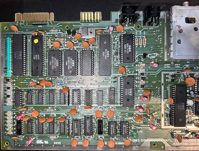
Several chips are socketed: SID, PLA, VIC-II, Kernal ROM, BASIC ROM, Character ROM, 74LS139, 74LS373, 74LS74 and 2x4066. It´s normal that the VIC-II and SID are socketed, but for the rest I think it is due to previous repair
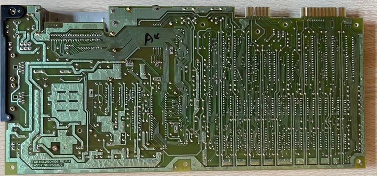
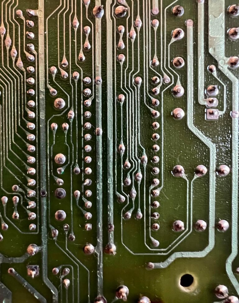
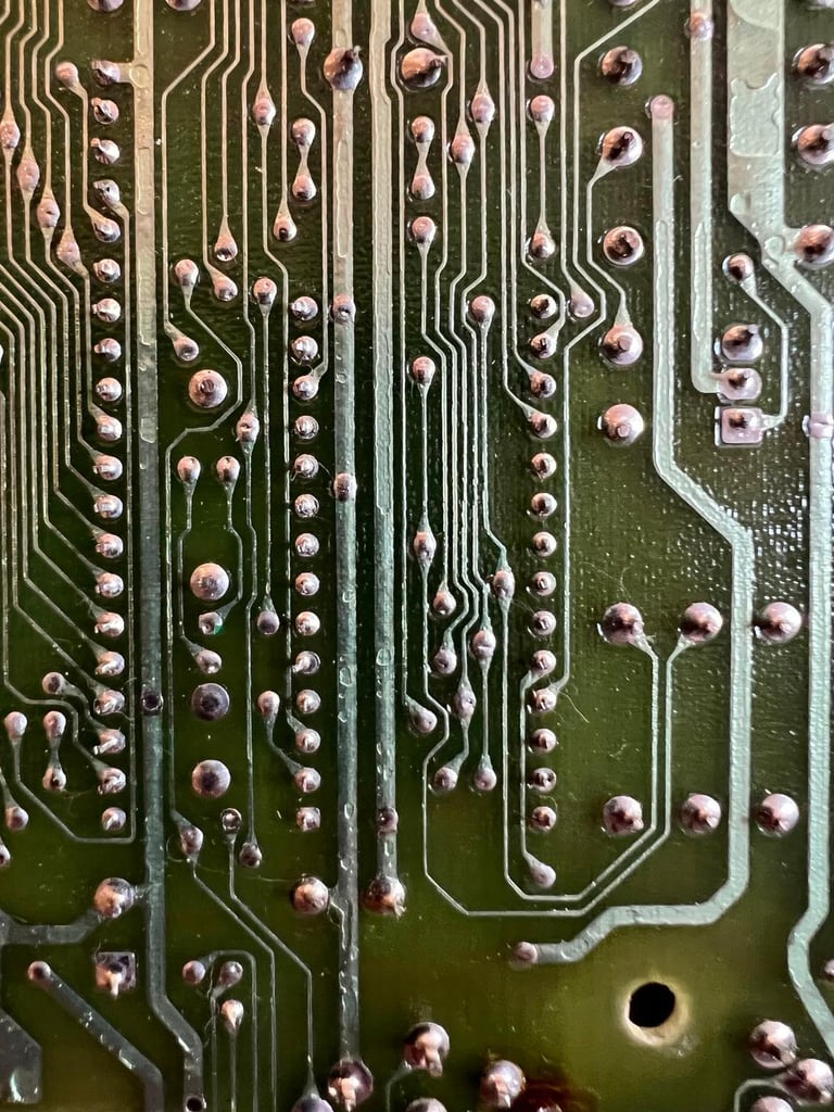
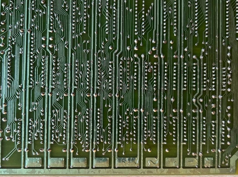
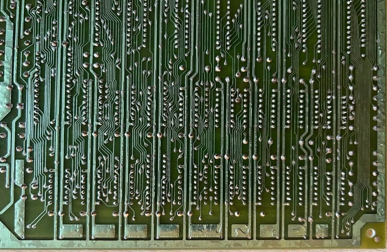
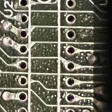
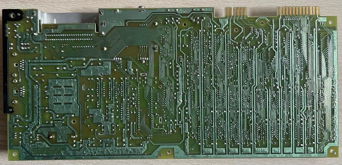
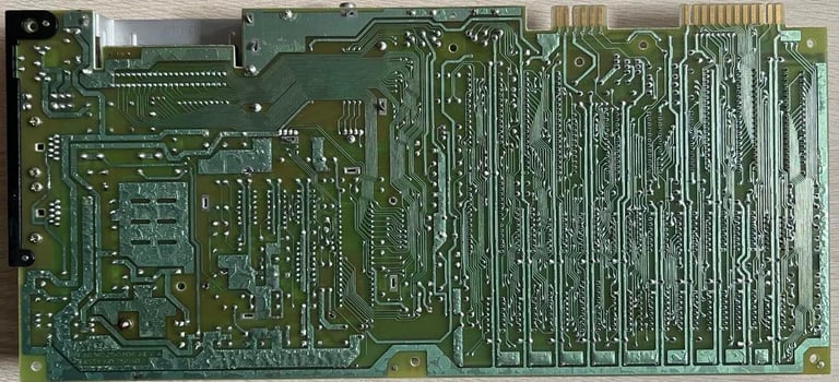
But the strange thing is that when I inspect the backside of the PCB I can´t see any sign of repair or rework? That doesn´t mean that it haven´t been repaired, but the repair is done very well. Or could it be that all these chips were in fact socketed at production time? Who knows...
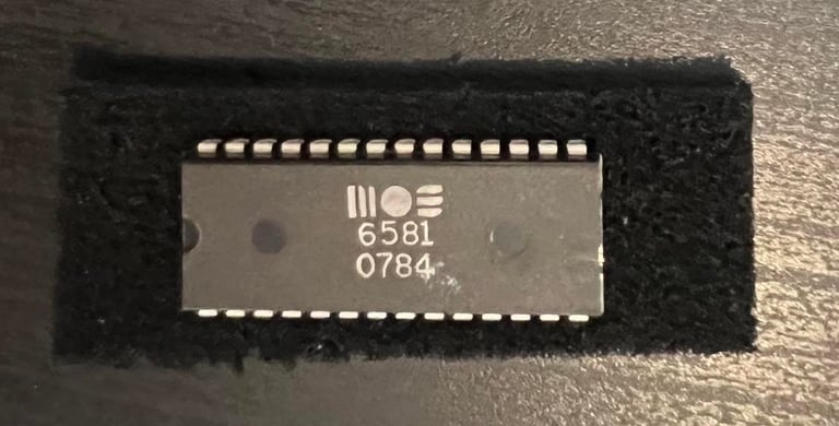
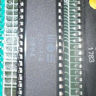
Most of the MOS custom chips were manufactured in 1983 and 1984. The only exception I can see is the PLA which are dated week 2 of 1987. This point to me that this C64 were repaired some time after 1987.
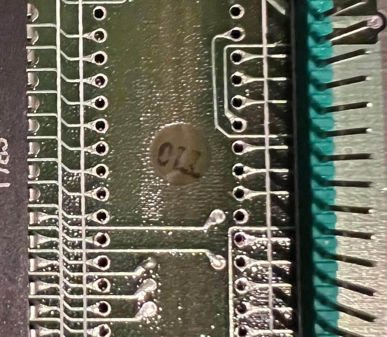
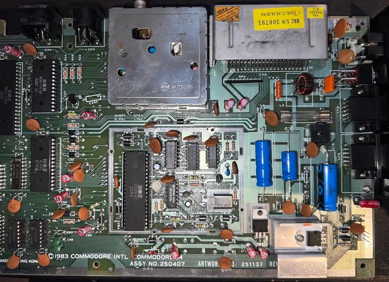
There is a sticker on the cartridge port where someone have made a circle around the number "15". I think this means that this machine was produced in week 15 in 1984 which makes sense in regards of the date the custom chips were produced (except the PLA which was replaced later).
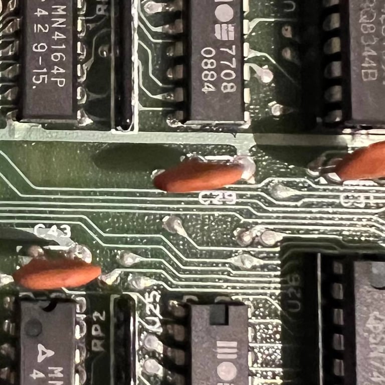
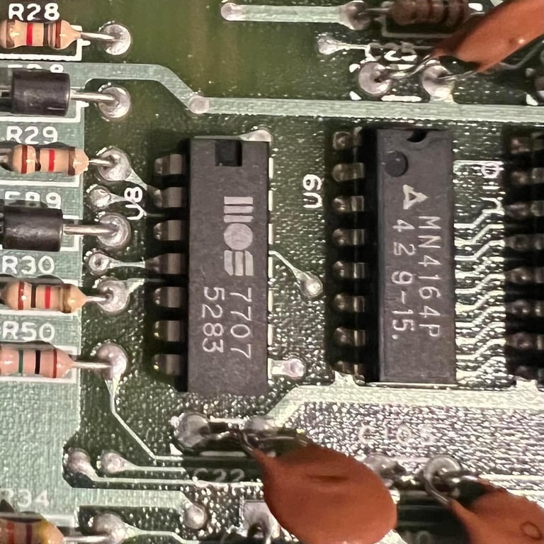
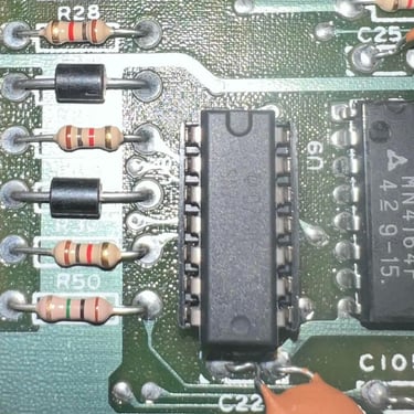
There are 2xMOS 7708 and 1xMOS7707. These are part of the "glue logic" in the C64, but unfortunately these are very prone to fail. So even if these work now I think they should be replaced with modern 74xx chips.
I can´t see any corrosion or rust
I can´t see that any of the electrolytic capacitors have leaked. That doesn´t mean that they have the correct capacitance still - so I will replace all of the electrolytic capcitors.
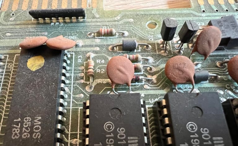
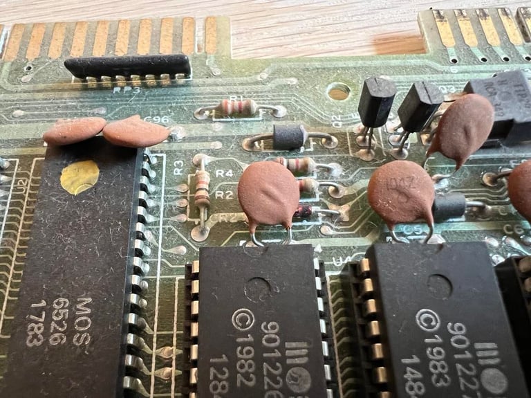
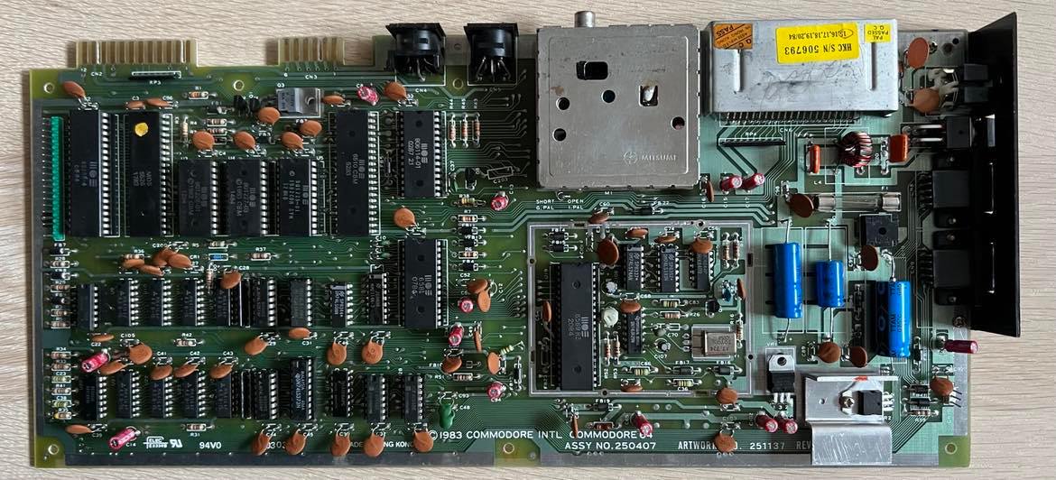
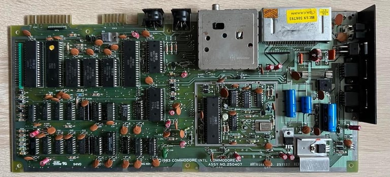
Below are some pictures of the main board before refurbishment which show some of the findings above. The first pictures show the front and back of the main board. Click to enlarge.
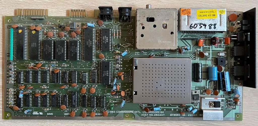
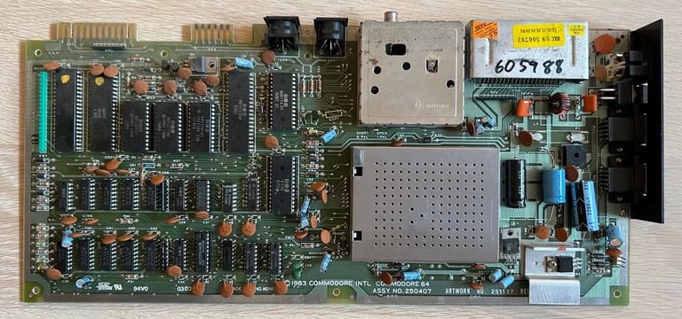

The datasette port needs a good clean.
Several chips are socketed. And also there are some MOS 77xx glue logic which are known to fail often.
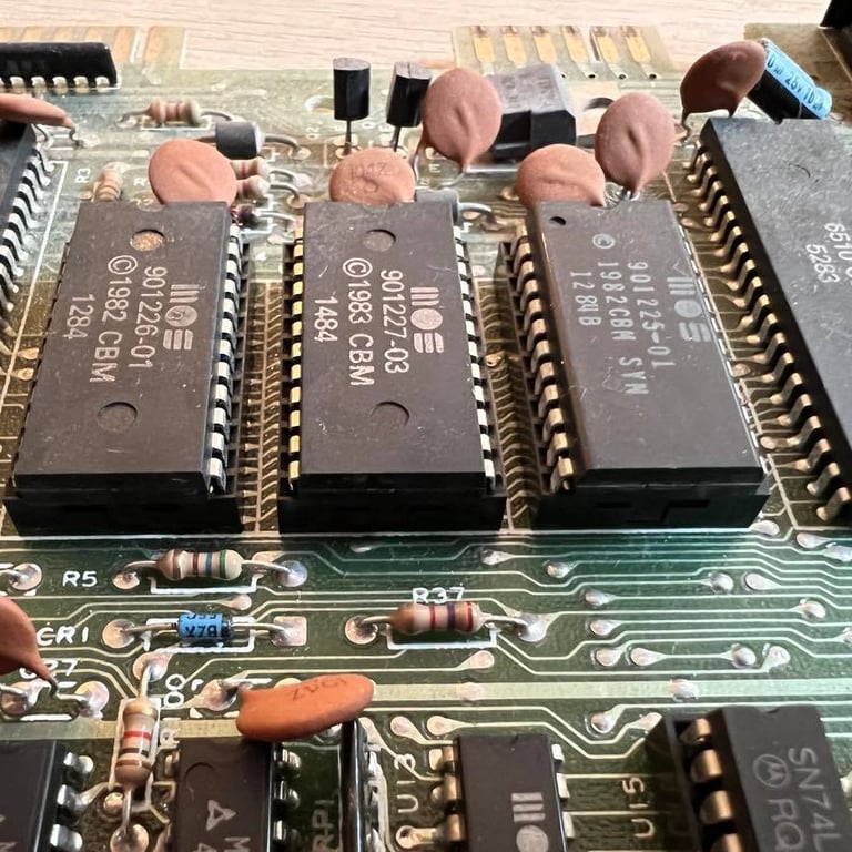
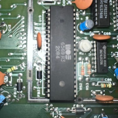
Production week 15 in 1984? I think so. Notice also the serial number (upside down) is written on the cartridge port. Just as for the keyboard.
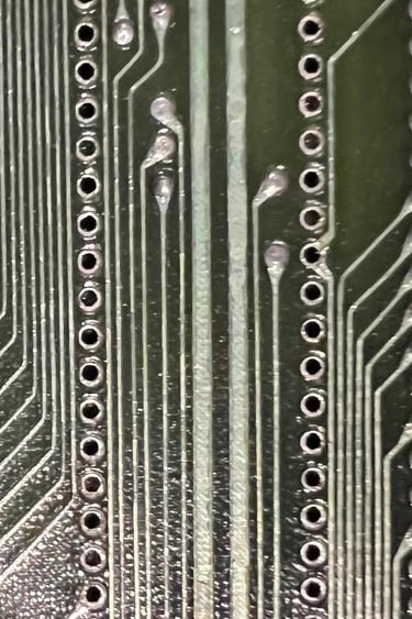
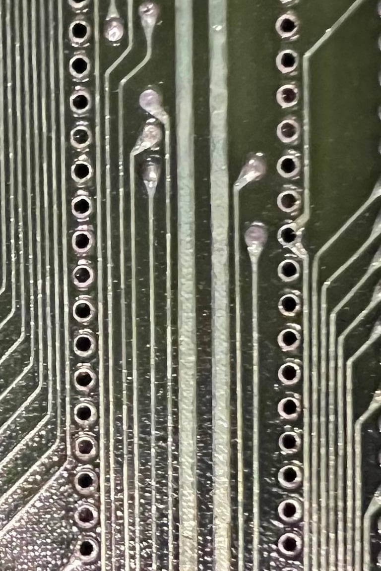
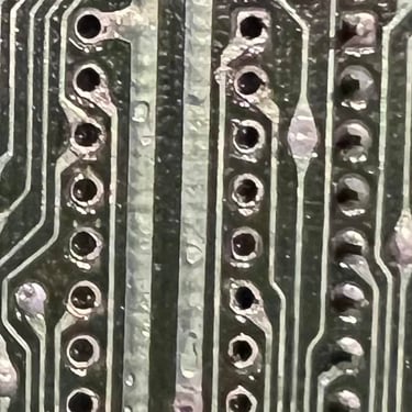
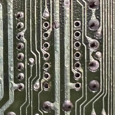
Were the sockets installed at time of production? The first picture is the backside of the PLA chip and the second show the backside of the glue logic chips (74xx, 4066 etc.). I can´t see any sign of flux residue which I would expect after a repair?
"Who you gonna call?" - DUSTBUSTERS! Yes, there is quite a lot of dust here, but this should be ok to clean off.
After the first initial visual inspection it is time to check to status of the main board. Does it work or not? But before I connect the PSU and TV to see, I do some initial preparations:
Check for short circuit which could damage the PSU (or chips for that sake)
Remove the SID chip. This is not required for the C64 to start
Check voltages
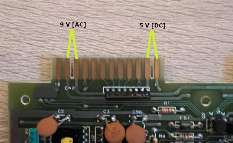
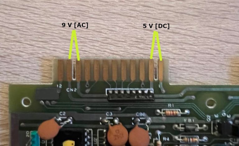
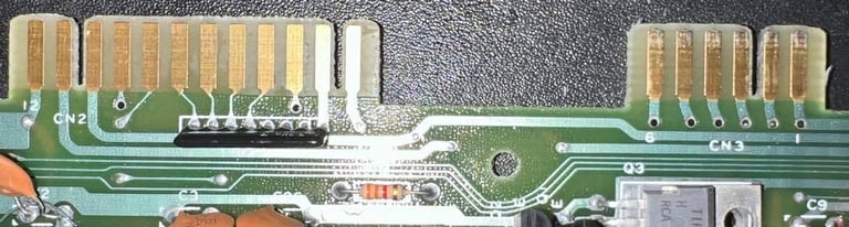
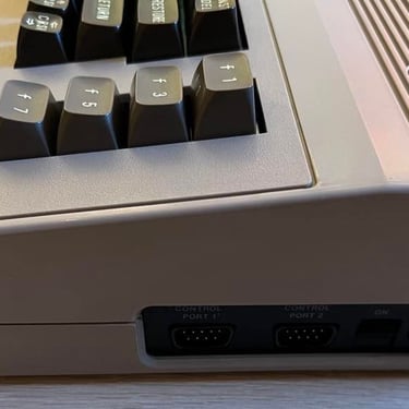
The first place to check for a short circuit is at the User Port. At the User Port both the 9V AC and 5 V DC are present - and these voltages are taken directly from the power supply (PSU). And I think it´s quite easy to remember these positions since they are between the two notches in the port. I can´t find any short circuit at these two positions. A short circuit here could potentially blow up your PSU. The picture below show the User Port and where to check for a short circuit (and later the voltages).
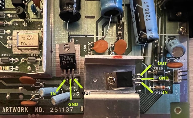
Next place to check for a short circuit is at the 5 V and 12V voltage regulators. These voltages are not directly from the PSU, but are derived from these. The 5 V is used only to supply the VIC-II. The 12 V is used to supply both the SID and the VIC-II chip. Why is there a separate 5 V for the VIC-II? Well, I´m not sure but I guess this could be related to preventing noise at the 5V rail from the PSU to the VIC-II chip - that would eventually disturb the video signal. If you check schematics of the C64 you will sometime see the word 5 V CAN which is the voltage from the 7805 voltage regulator. This "CAN" I think may stem from the VIC-II being "canned" in the RF-shield - and therefore the 5 V CAN.
I find no short circuit here either. The way I check it is using the multimeter in the "beep mode" and check that there is no beep between ground (GND) and in/out of the 7805 and 7812. Picture below show the positions of the GND/IN/OUT. As you might guess; 7805 is the 5 V regulator and 7812 is the 12 V regulator.

Knowing that there are no short circuit it is safe to power on. But I highly recommend to remove the SID chip before doing so. These chips are really rare these days so we should all try to preserve them as good we can. And the C64 does not need the SID chip to boot to blue screen. So as best practice I always remove these valuable chips before first power on.

Ok, it´s time to power on. But on first power on I do not connect the A/V to the TV. I just power on to measure the voltages to make sure that they are ok. Table below shows the recorded voltages before refurbishment. As far as I can see the voltages are ok for the C64 to function - so there is good hope! I notice that the input voltage to the 7812 is 23.32 V which I think is quite high. It´s not a problem since the output is fine with 11.9 V, but I wonder if this would improve with new capacitors.
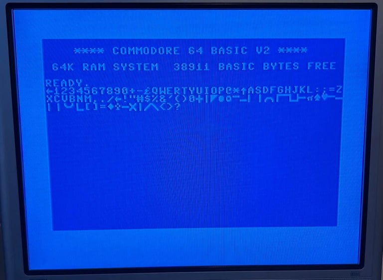
It´s time to connect the C64 to the TV. I have a good feeling here that this will work without any major repair!
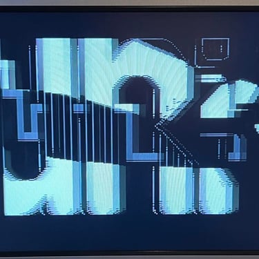
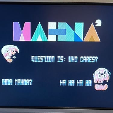
But... hehe... NO! It doesn´t! No black screen, no garbaged screen... But a wild colorful demo! Hehe! Oh my! The link below shows a small video of the result!
Colorful fault on the Commodore 64 ser. no. 605988
OK! This Commodore 64 needs repair! No doubt! Where to start looking for a fault? Well, I will start with some investigation around the VIC-II chip - either that the chip is defect or that some surrounding chips / capacitors / oscillators are defect? But before I start fault finding I will clean the board properly. It will not fix this problem, but the board needs a good cleaning! I wash the PCB thoroughly with luke warm water and soap - and afterwards rinse with a lot of isopropanol to get the water to vaporize fast.
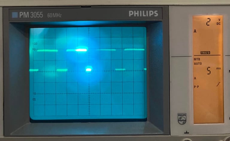
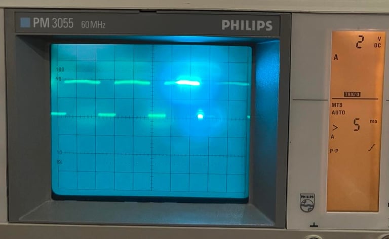
I think that the fault could be located around the VIC-II circuit. Either something wrong with the oscillator circuitry, the glue logic or the VIC-II chip itself. To investigate I use the oscilloscope on some of the pins on the VIC-II chip and compare the signals to those presented in the Signal Reference for VIC-II. The signal on PIN #17 is the Phi 0. This is the system clock (1 MHz) that the VIC-II outputs for the 6510 CPU. And this signal looks ok. Picture to the left shows the signal from this faulty C64 and the picture to the right shows the signal from the signal reference bank. This signal looks ok - and identical to the reference signal.
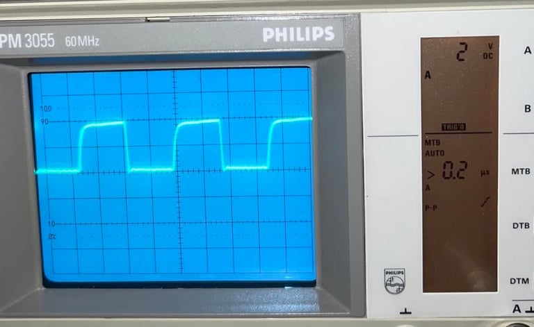
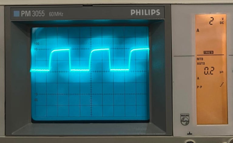
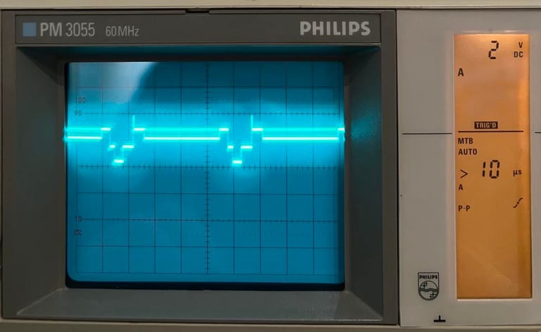
Next signal is the Sync / Lumimance output on PIN #15. And here there is something different! Picture to the left is from the faulty C64 and to the right is a picture from the signal reference bank for the same pin. I wonder if the VIC-II itself is faulty.
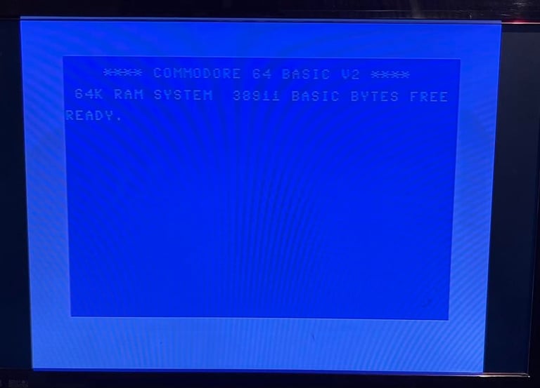
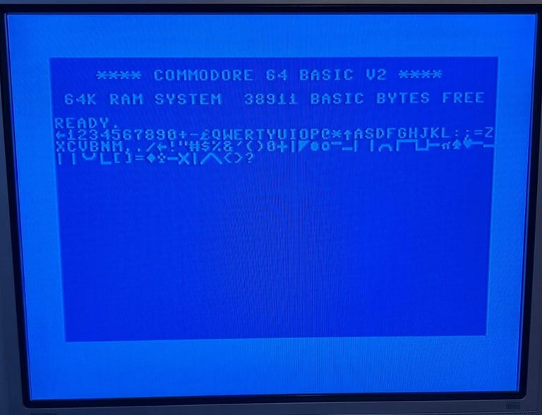
The VIC-II chip is socketed so it easy to replace this with a known good working chip. And with a "new" VIC-II chip in place a familiar picture appear!
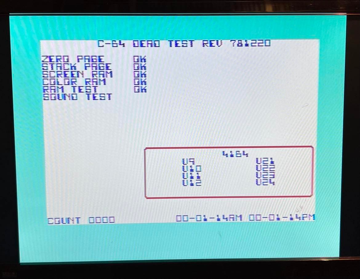
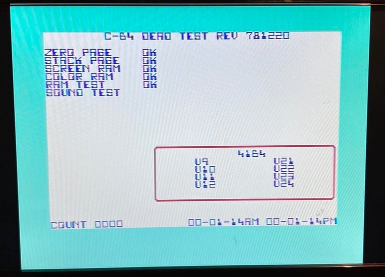
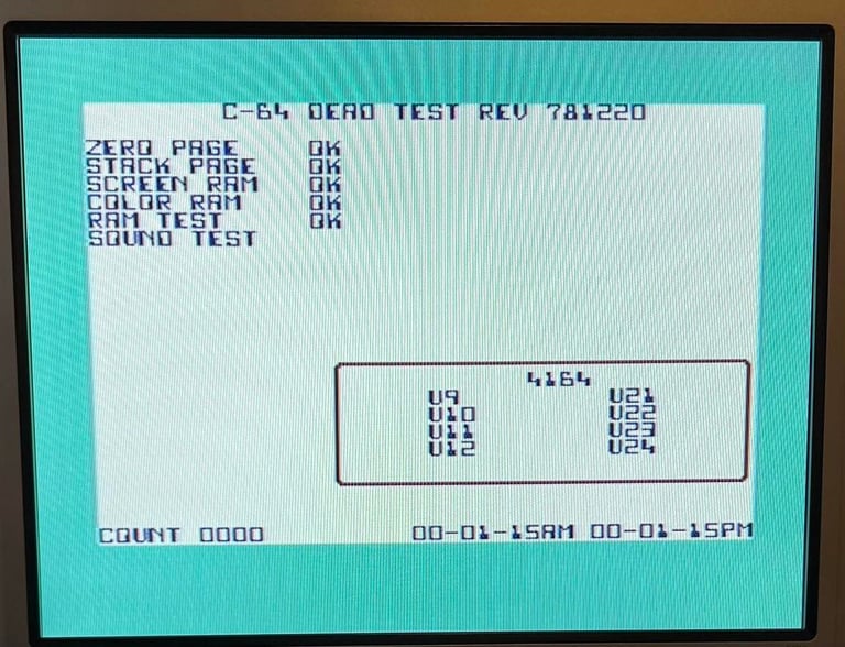
This looks promising! Next step is to test with the Dead Test cartridge. See picture below.
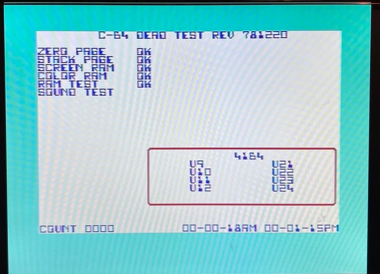
Notice that the two clocks at the bottom right doesn´t match. This means that something is wrong either with one of the CIA chips or something related to these chips.
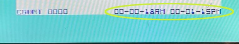

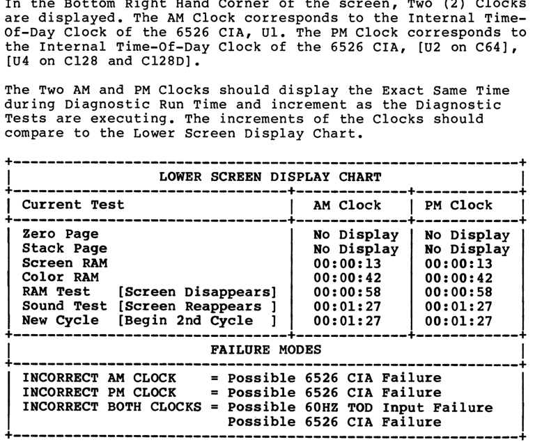

Checking the manual for the Dead Test cartridge I find the following:
According to the manual the AM / PM clock should show 00:01:27 during the sound test. But on this C64 the AM display 00:00:18 and the PM display 00:01:18. Now that doesn´t mean that the PM display is wrong. The table above is for a NTSC C64 while this C64 is PAL. The NTSC have a screen refresh rate of 60 Hz while the PAL is only 50 Hz. So the NTSC is approximately 20 % faster in regard of the screen refresh - this again will result in "more ticks" in the AM/PM clock.
That leave us that in accordance with the manual there is a possible failure in the internal time-of-day clock in the U1 6526 CIA #1 chip.
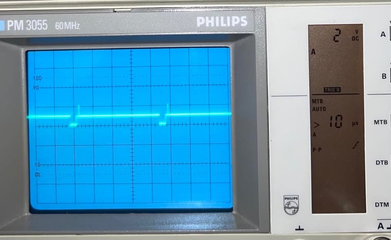
My first idea is to check PIN #19 on the CIA#1 chip this is the "TOD" (TimeOfDay) clock output from the CIA chip. My guess is that signal is corrupt in some way. But when I use the oscilloscope on this PIN #19 and compare it with the signal on PIN #19 from the Signal Referance Bank I can´see any difference? So it looks ok from the outside. See pictures below. Picture to the left shows the out on PIN#19 on the faulty C64 and picture the right show the picture from the Signal Reference Bank.
Nevertheless, I choose to desolder the CIA#1 chip. The way I desolder these 40-pin chips is to first use the PACE desoldering gun. When all the solder is removed I carefully use hot air around the chip from the top side, and while heat is added I gently lift the chip from the board with a small flat screwdriver. With this method (which I learned from Adrian´s Digital Basement) I manage to remove the chip without lifting any pads. See pictures below.

I solder in a 40 pin socket and test again with a known working CIA chip. And, yes, now it works! So the old CIA is probably marginal. I need to order both a "new" VIC-II and CIA chip. Will be a quite expensive repair this! Below is a picture of the testing done with the known working CIA chip in this C64. As displayed below the AM and PM clocks are now identical and correct.
As mentioned in the beginning this main board have 1 x MOS 7707 and 2 x MOS 7708 used as "glue logic". I´ve seen before that these fail and they are known for failing due to age.
As a preventive maintenance I replace these with modern replacements (source: https://www.c64-wiki.com/wiki/MOS_Technology_Products):
MOS 7707 <> 7406
MOS 7708 <> 74LS257
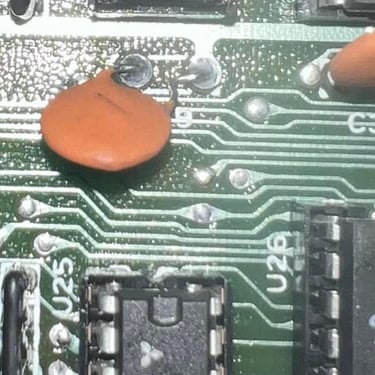
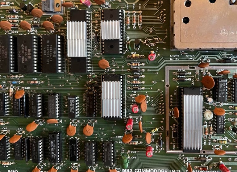
The desoldering of these chips are done without any issues. No traces lifter or other damage. Sockets installed. Pictures below show a gallery of the main board where these chips are removed as a quality of the desoldering process.
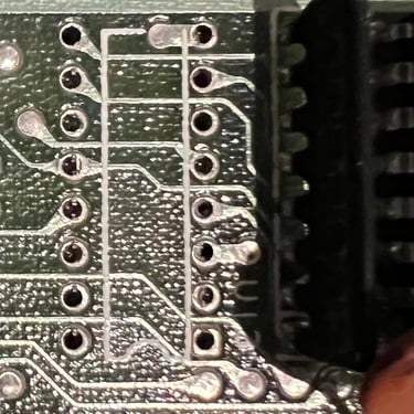
The RF-shield around the VIC-II area is desoldered and removed. This metal shield have no meaning in the year 2022 - it only adds more heat to this area. It requires a bit of heat to remove this shield. I do this by using a combination of desoldering gun, hot air and a soldering iron. Below is a picture with the RF-shield removed. Nothing was damaged during the process.
Some "new" chips are ordered from Retroleum : 1 x 6526 CIA and 1 x 6569 R3 both from the year 1984. Replacement chips 7406 / 74LS257 I already have in stock (orderd from Mouser Electronics). Below is a little gallery with all the "new" chips in place (click to enlarge) from left to right; CIA, 7406, 74LS257 and VIC.
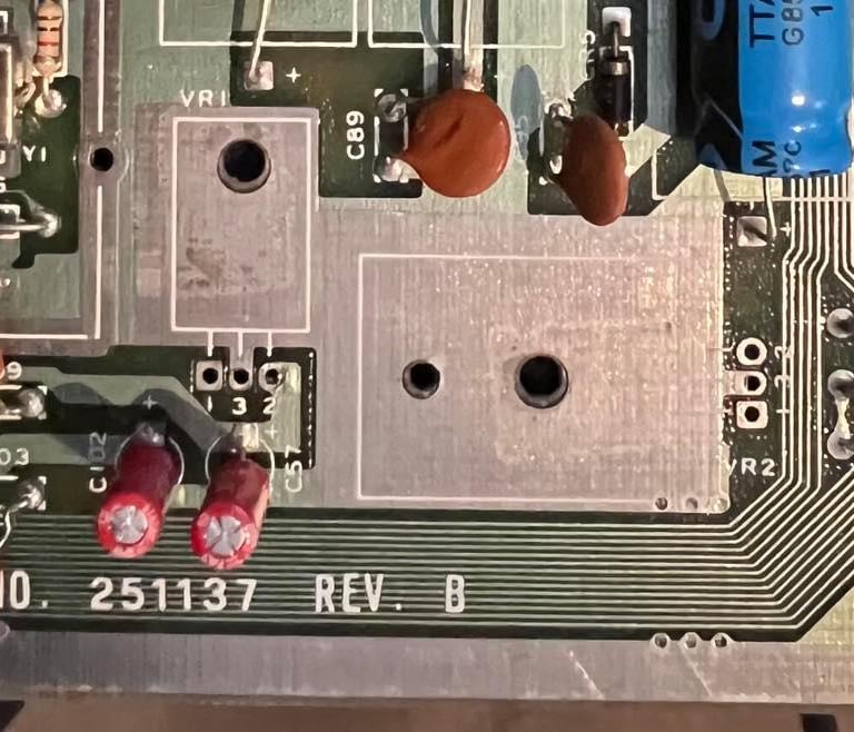
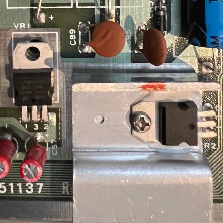
As mentioned earlier there are two voltage regulators. Even if these are ok at the moment they are close to 40 years old. And if one of these fails, and he voltage exceeds acceptable tolerances, it could cause damage to the much appreciated VIC-II and SID chip. Therefore these are replaced with new. It´s quite straighforward to desolder these and solder in new ones. Note that it´s only the 7805 (+5V) regulator which is mounted on a heat sink with some heat paste. The 7812 (+12V) is not mounted this way - and this is correct from factory.
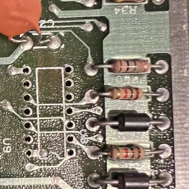
Below you find a picture of the voltage regulators removed, and a picture with the new ones installed (click to enlarge).
Before I start the recapping of the mainboard I do a small, but important, task: I clean the datasette- and userport. In order for the C64 to operate flawlessly these contact ports needs to be clean. To clean them I use (carfully) a rubber eraser to get most of the fat and residue away. Finally I clean everything with isopropanol and some contact cleaner.

Electrolytic capacitors
These machines are almost 40 years old. And electrolytic capacitors will normally change their capacitance due to drying out - and in some cases (not usual in the C64) start to leak. As a preventive measure I always replace the electrolytic capacitors on the mainboard - and in the RF-modulator. I use quality capacitors either ordered from Retroleum or Mouser (tip: if you order from Retroleum you will get all capacitors in one package ready for use).
A complete list of all the electrolytic capacitors for this mainboard, assy 250407 artwork 251137 (REV B), can be found in the capacitor reference bank.
A picture of the mainboard with all the new electrolytic capacitors are shown below.
Left and right side of the mainboard - closer look.


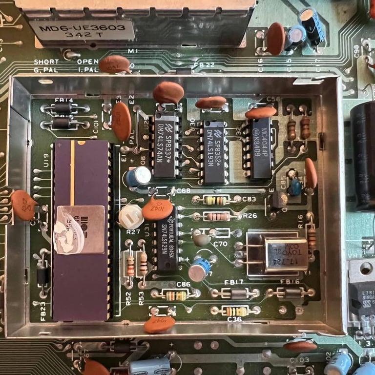
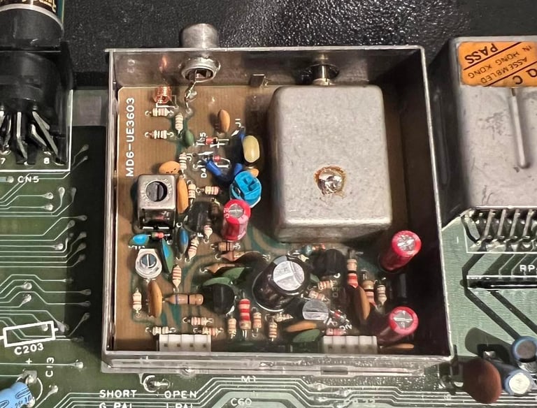
RF-modulator
This C64 has the MD6-UE3603 version of the modulator. Checking the list in the Capacitor Reference Bank I see that there are four electrolytic capacitors in this version which needs to be replaced with new (of good quality).
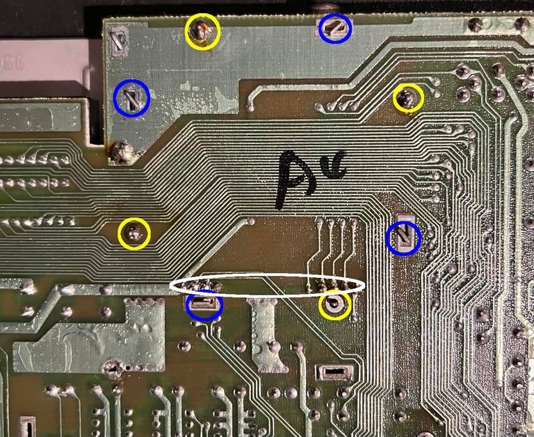
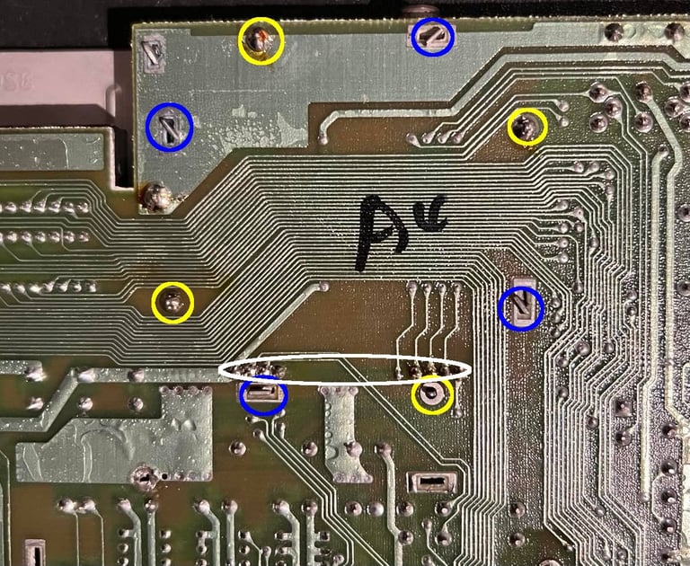
Replacing the capacitors itself is straightforward, but to get the RF-modulator container out of the mainboard can be a pain. The reason is that there are four tabs, four thick soldered pins and eight thin soldered pins holding the container onto the mainboard. All of these has to be cleared in order to remove the RF-modulator from the board. The position of these are shown in the picture below (blue: tabs, yellow: thick pins and white: thin pins). Notice that one of thick pins and the corresponding tab is not soldered/bent by factory. I´ve seen this from time-to-time.
The way I remove the RF-modulator container is by:
Bend the four tabs so that they are align and parallell to the holes
With additional flux and a soldering iron (to add extra heat) I use the desoldering gun. I find that by using both the soldering iron and the desoldering gun at the same time that I get most of the solder away from the four thick pins.
With the desoldering gun (only) I remove the solder from the eight thin pins
Carefully pry a small flat screw driver under the edge of the container. Then I add hot air around the thick and thin pins while GENTLY prying the RF-modulator off the board with the screw driver.
The result of the desoldering is a success. No damaged traces or pads on either mainboard or RF-modulator PCB. See picture from mainboard below.
Four electrolytic capacitors are replaced with new quality capacitors:
1 x 10 uF [16 V]
2 x 100 uF [10 V]
1 x 470 uF [10 V]
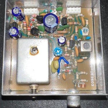
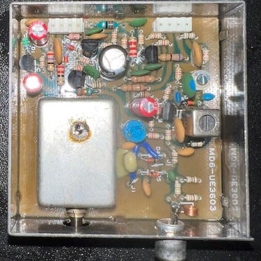
Pictures below shows the RF-modulator with old capacitors (left) and new capacitors (right).

After replacing the capacitors, the RF-modulator is soldered back to the mainboard. And I check that the C64 still displays the good old blue screen - which is does.
Now since all capacitors are changed (both RF-modulator and mainboard) and the voltage regulators are changed I check all voltages are ok. The table in the beginning is updated with the new voltages. All looks ok!
Heat sinks
Heat sinks on chips on a 40 year old machine? Yes, I think that this is wise. There is no guarantee that it will prolong the lifespan of some chips, but I think that heat in general is a factor decreasing the lifespan. So as a preventive measure I add heat sinks on the most crucial chips; VIC-II, PLA, SID and CPU.

Testing
The C64 is completely assembled and it is time for testing! This is done in two stages:
Testing the basic functionality such as CPU-, RAM-, ROM-, PLA-, CIA-, VIC- and SID chip. And also the keyboard and cartridge port.
Testing the C64 under normal operation; loading games and demos by datasette and floppy and seeing that everything works as expected
Basic functionality test
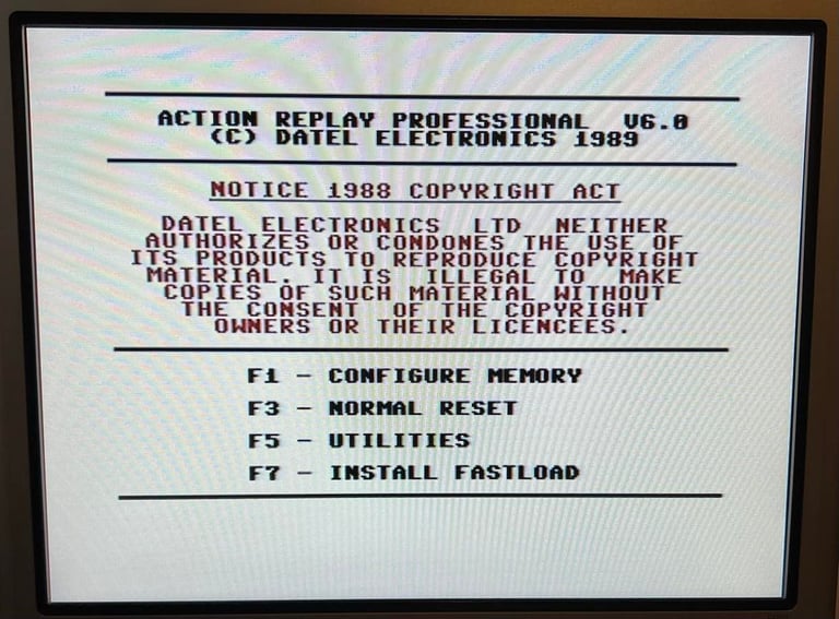
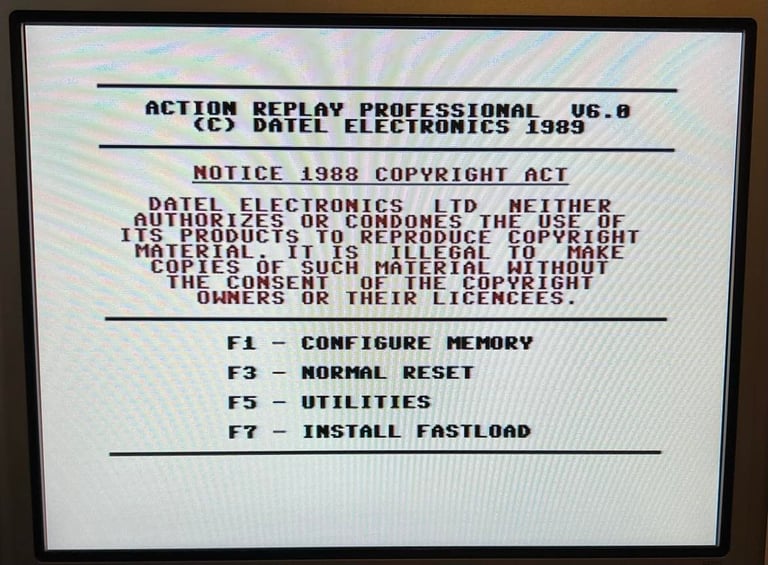
Dead test cartridge: This test checks both the 6526 CIA chips, 64kB RAM (also the 1k Color RAM), 6567 VIC-II, 6510 CPU, the PLA and the 6581 SID. The dead test cartridge is a great tool for testing the "core" of the C64 system. All test pass with flying colors.
Keyboard test: Simply testing all keys on the keyboard making sure that they all work. Test passed.
Cartridge test: Checking that the cartridge port works as expected. Test passed.
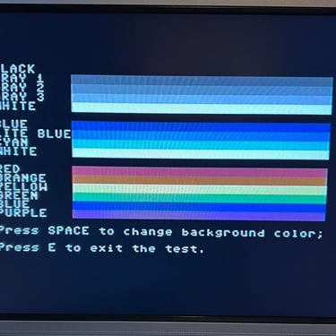
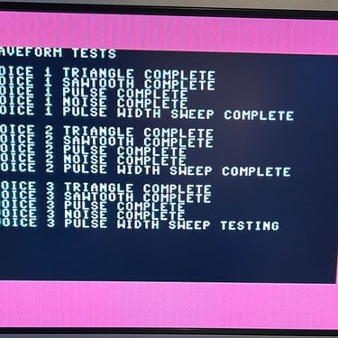
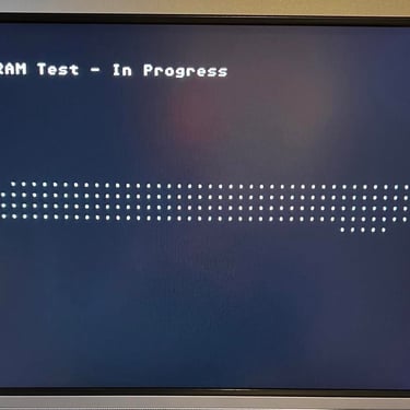
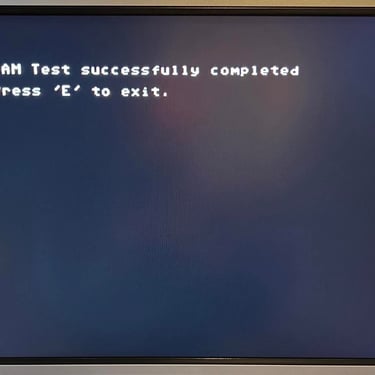
SID, VIC and RAM test: A more elaborate testing of these (compared to dead test) using tools such as 64 Doctor and Commodore 64 SID tester. Test passed (click to enlarge).
Extended functionality test
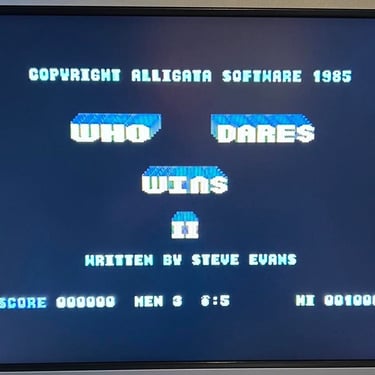
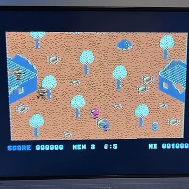
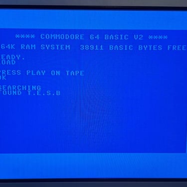
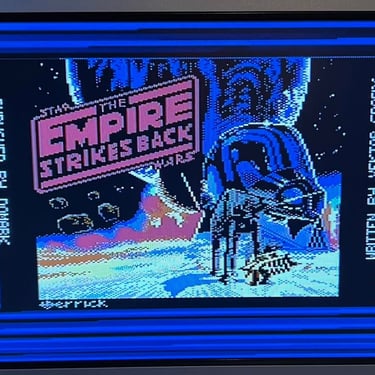
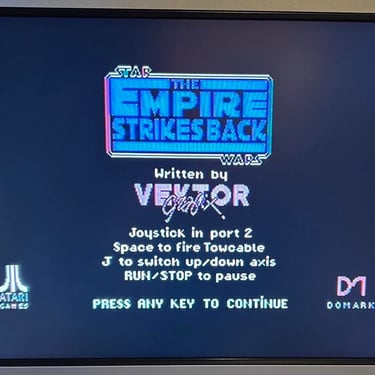
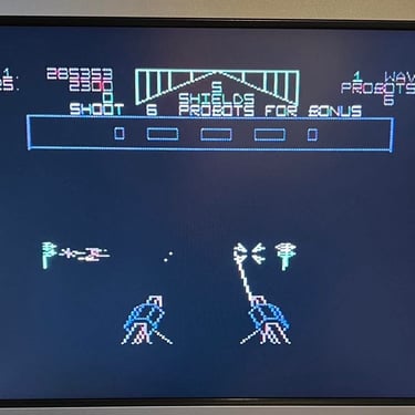
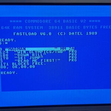
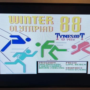
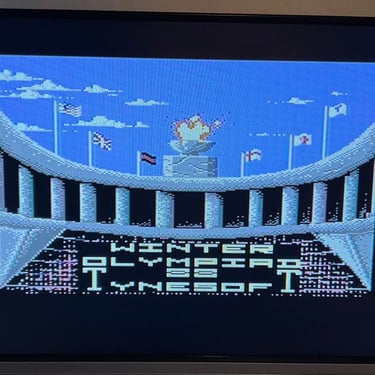
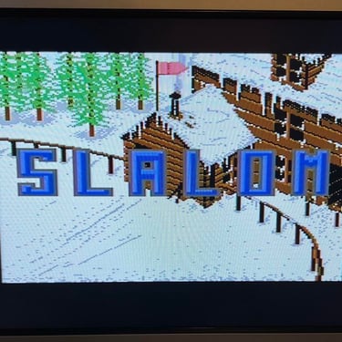
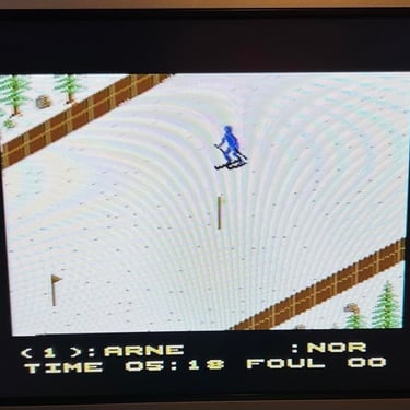
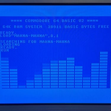
Using the UltimateII+ cartridge I test the C64 as much as possible; loading games and demos from datasette and floppy. Checking that everything works "as expected" - that sound is ok, graphics looks ok and that all normal operation are ok. Test passed.
Below are some pictures from the testing (and yes, this part is awesome! I really love looking at these demos and play games!)


Final result
"A picture worth a thousand words"
Below is a collection of the final result from the refurbishment of this C64. Hope you like it! Click to enlarge!
Banner picture credits: Evan-Amos