

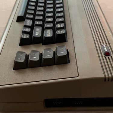
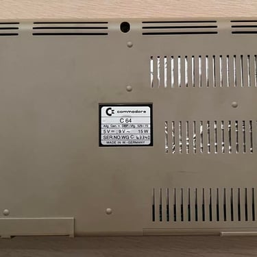
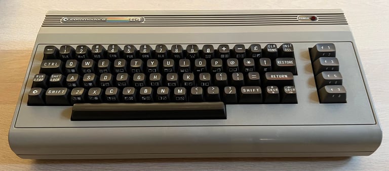
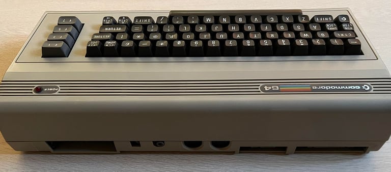
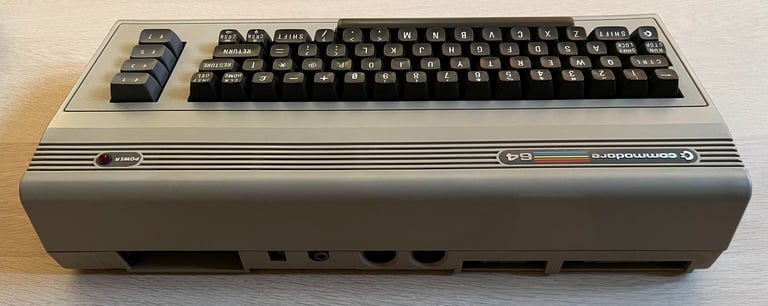
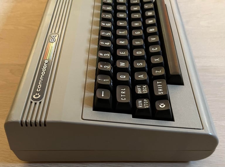
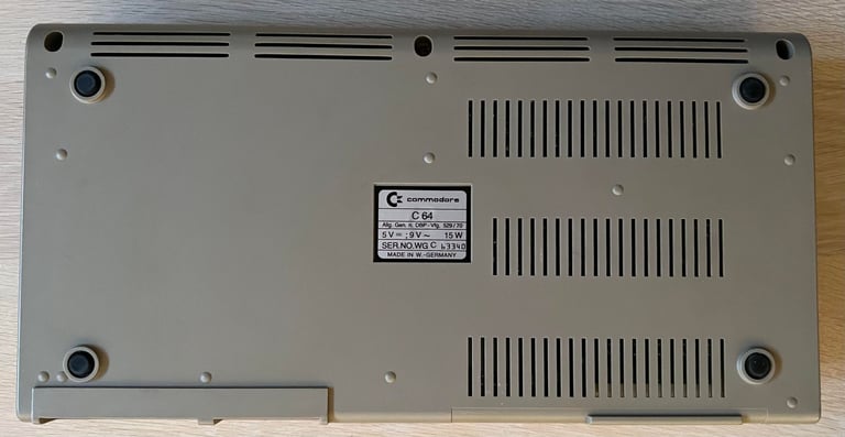
C64 Breadbin
Ser. No. 63340
Assy 250407
Artwork 251137 (REV B)
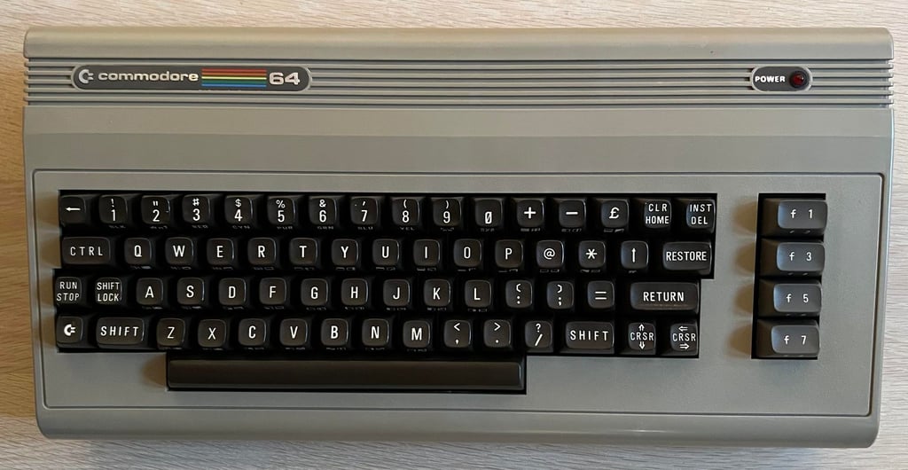
Starting point
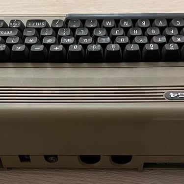
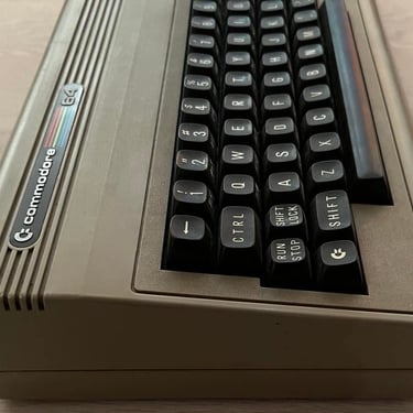
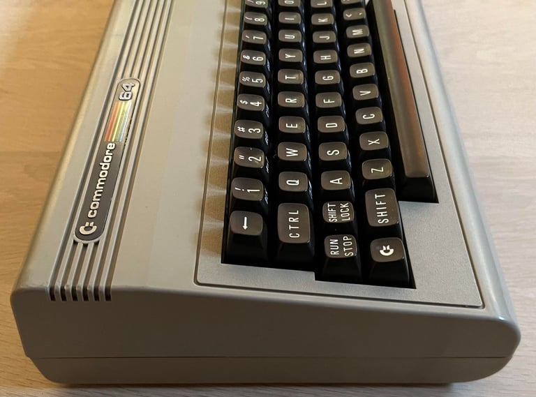
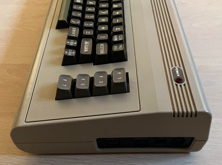
This C64 breadbin looks promising. It´s dirty - and some sticky stuff - but otherwise looks intact. Also, the chassis (top- and bottom cover) are more yellow than I like. Last thing is that it smells a bit (not much!) of tobacco!
Below you will find some pictures before I begin the refurbishment (click to enlarge). Looking forward for this refurbishment!
Refurbishment plan
The refurbishment plan for this C64 breadbin (some of them in parallell):
- Clean and remove stains from the chassis
- Clean and restore the keyboard
- Refurbish main board (cleaning, checking, repairing, replacing capacitors and voltage regulators etc.)
- Recap RF-modulator
- Verify operation by testing
The plan can be updated during the refurbishment process. Sometimes I discover areas that needs special attention.
Exterior casing
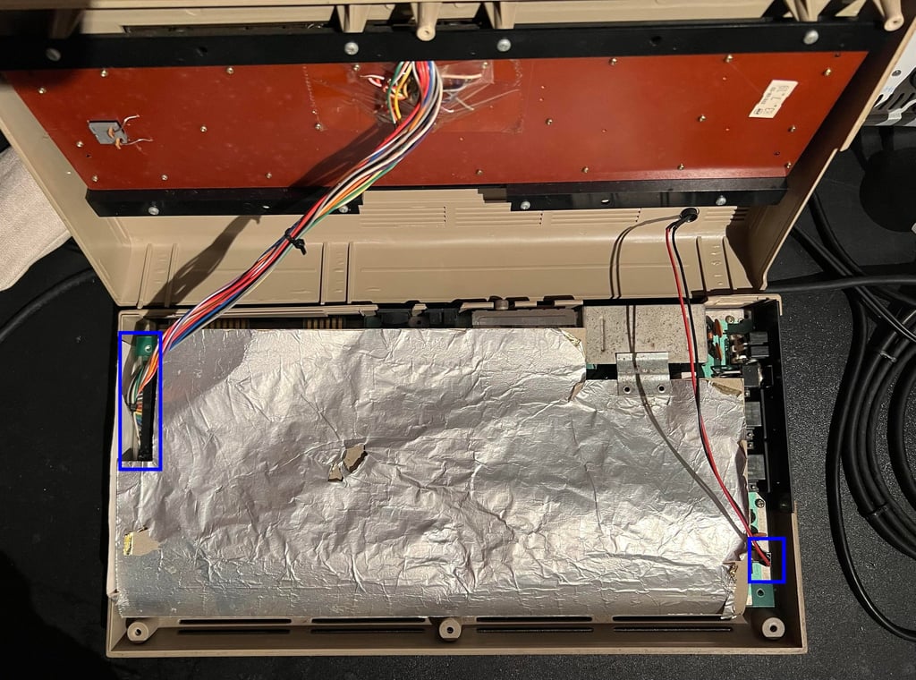
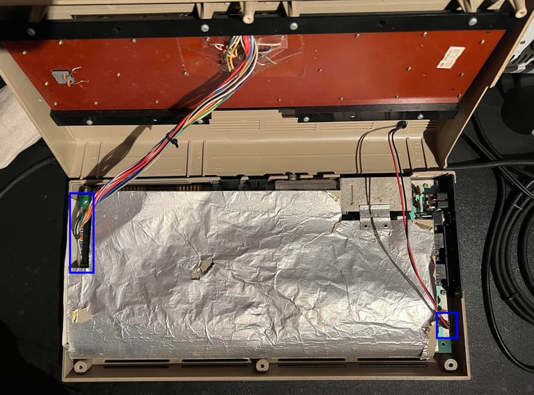
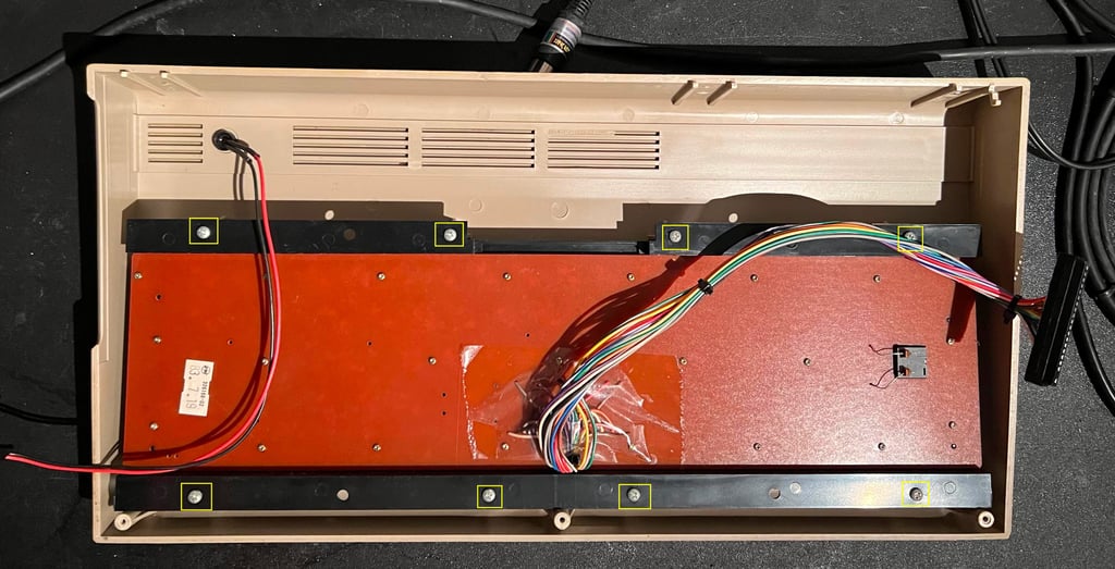
The top- and bottom case are separated by removing the three screws at the bottom. The top case if carefully tilted so that the LED and keyboard connector can be removed (yellow squares).
When the cardboard is lifted the PCB is revealed - it is dirty but looks in otherwise good condition. Note that all the PCB screws were removed, but they followed the machine in a separate plastic bag.

The PCB is lifted out and the cardboard removed. The RF shield cardboard will be thrown away - this is not required in modern times. It only generates heat inside the Commodore 64. Next the eight screws holding the keyboard are removed (yellow squares) which now separates the top cover and the keyboard.

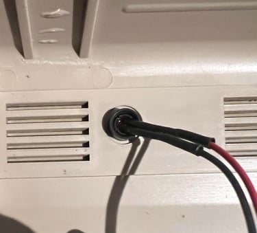
Although not strictly necessary I remove the LED. First the small plastic ring holding the LED clip is loosened. Next the LED itself is pushed - from the outside of the cover and inward - until it "pops" out of the clip. Finally the clip itself is carefully pushed - from the inside and forward.

Keyboard
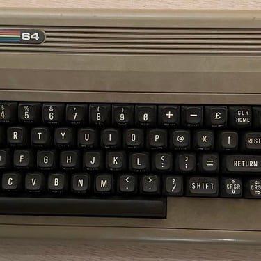
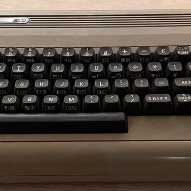
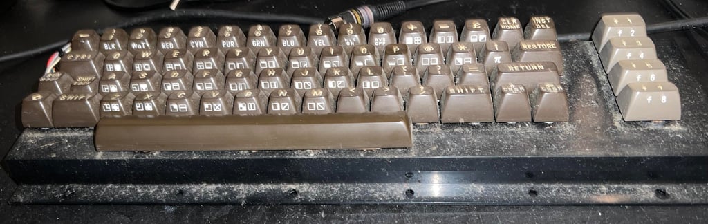
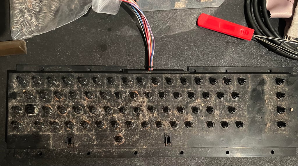
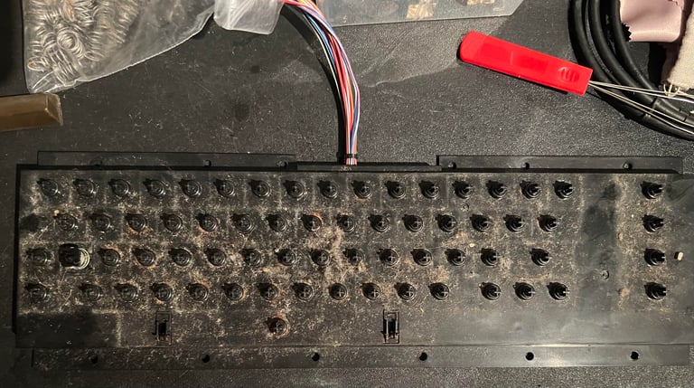
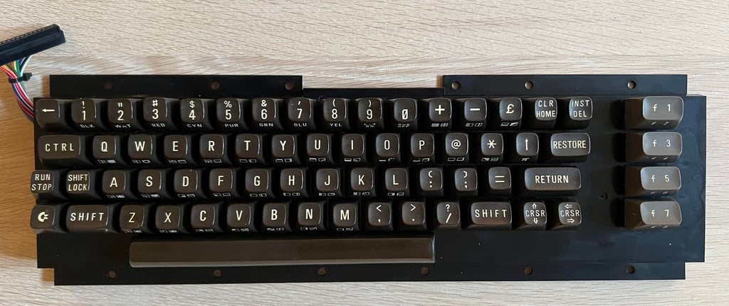
The keyboard is very dirty - and several of the keys are not working (in the sense that the C64 does not register the key being pressed down). This is quite common, more or less something that happens to all Commodore 64 machines if they are not refurbished after 40 years. But the good thing is that this can be fixed.Below is a picture of the keyboard before cleaning and refurbishing.

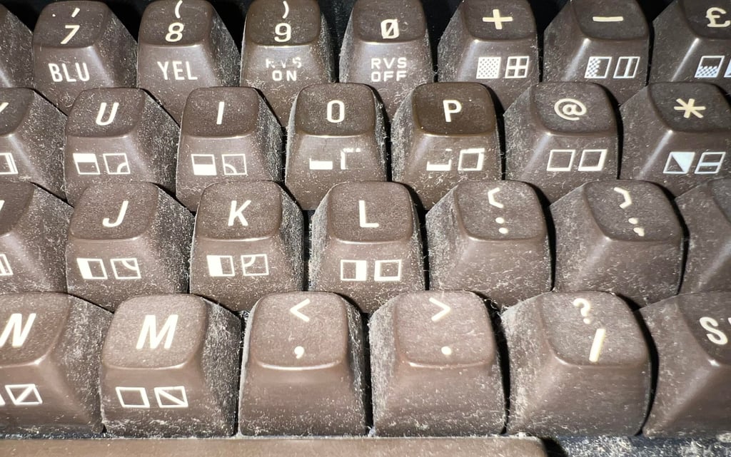
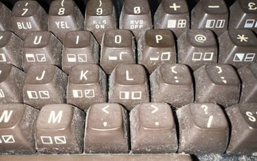
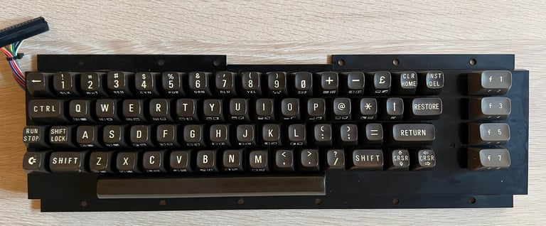
I notice that some of printing on the front of the keys is missing. This is also quite common on the breadbin keyboard since the front print is much more fragile than the top printing. See picture below.
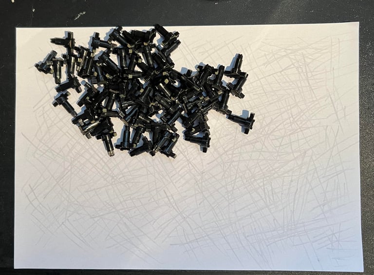
Each keycap is removed with a keycap puller, and each spring is placed in a plastic bag. Note that the spring for the spacebar is bigger than the rest so it is a good idea to place this one in a separate plastic bag. As seen from the picture below there is a significant amount of dust and grease here.
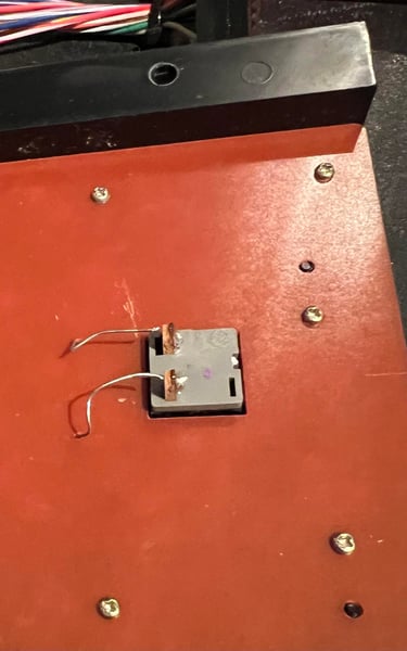
To remove the SHIFT LOCK key the two wires on the backside are desoldered - see picture below. The SHIFT LOCK key is very easy to remove now: just give it a firm push from the backside until you hear a small "pop". When the SHIFT LOCK key is removed all the screws are now removed and the plastic casing and PCB are separated.

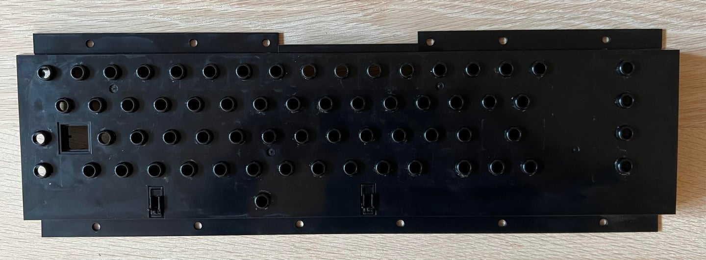
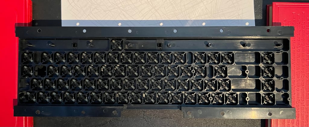
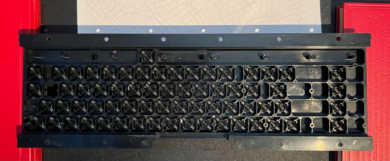
The plastic chassis is placed in mild soap water for 24 h and then cleaned with a soft paint brush. The result, as seen below, is very good. The plastic is now clean and look good as new.

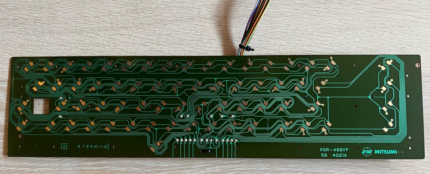
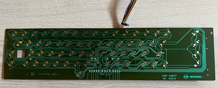
This is a Mitsumi keyboard - version KSR A66YF. There is very little grease on the PCB, and I can not see any corrosion on the traces. The PCB is cleaned carefully with some some isopropanol. Note that it is important to be careful when cleaning the carbon pads (for the keys). These are fragile and it is enough just to gently wipe them with some isopropanol on a piece of paper towel. As seen from the picture below the PCB looks very good after cleaning.
Each key plunger is cleaned individually. The way I do this is to carefully rub the plungers on a clean paper just to scrape off the residue and grease on them. This will work for most of the cases, but if this is not sufficient I clean some of the plungers with some isopropanol on a Q-tip. I find this method to be the most gentle, but also the most effective. When all the keys are cleaned they are put back in the plastic chassis. I place the plastic chassis between two books to lift it up - then insert one plunger at a time.

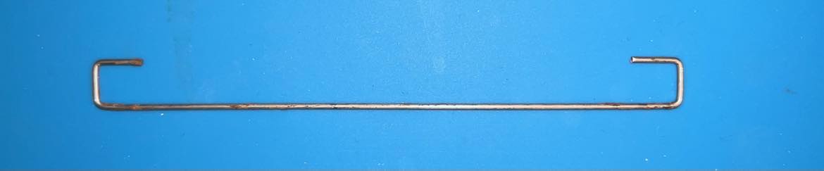
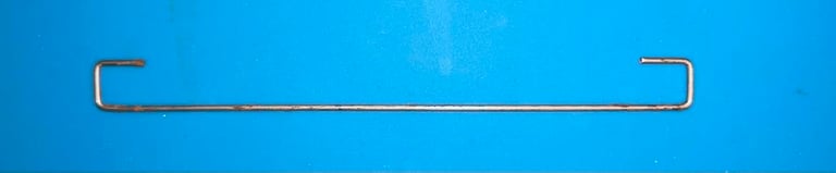
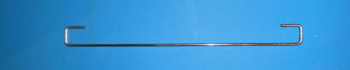
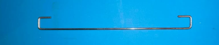
There are some rust on the metal bracket holding the space bar. Most of this is removed with some vinegar and a metal sponge and then cleaned with isopropanol. It is not 100 % perfect, but I think this is as good as it gets. In the pictures below are some "before" and "after" pictures. It is not so easy to see in these pictures, but most of the rust is removed.
All the keycaps are cleaned with soap water - and not retrobrighted with hydroperoxide. I think I will try instead to leave them out in the sun (when the spring is here). But anyway, I think the keyboard now looks very good already. See picture below.
Mainboard
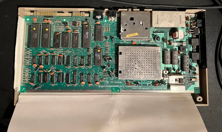
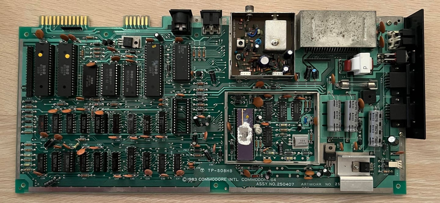
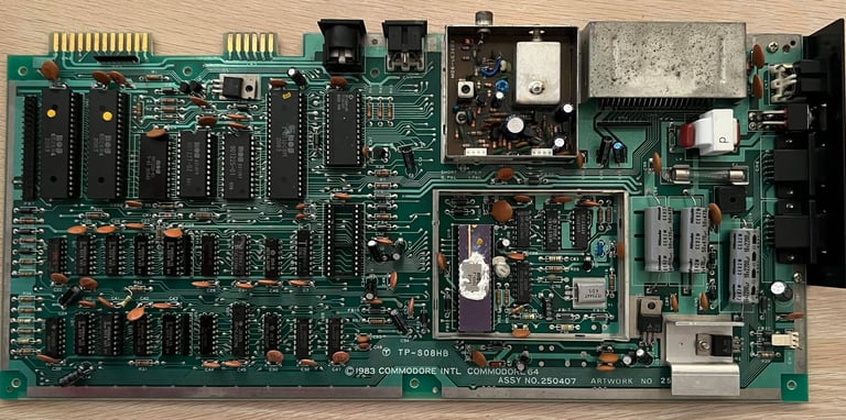
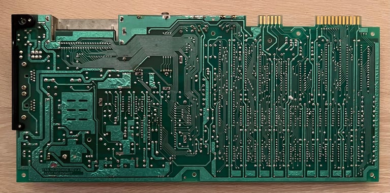
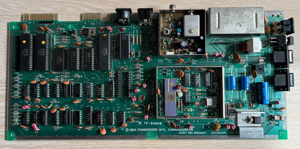
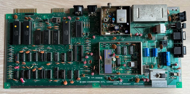
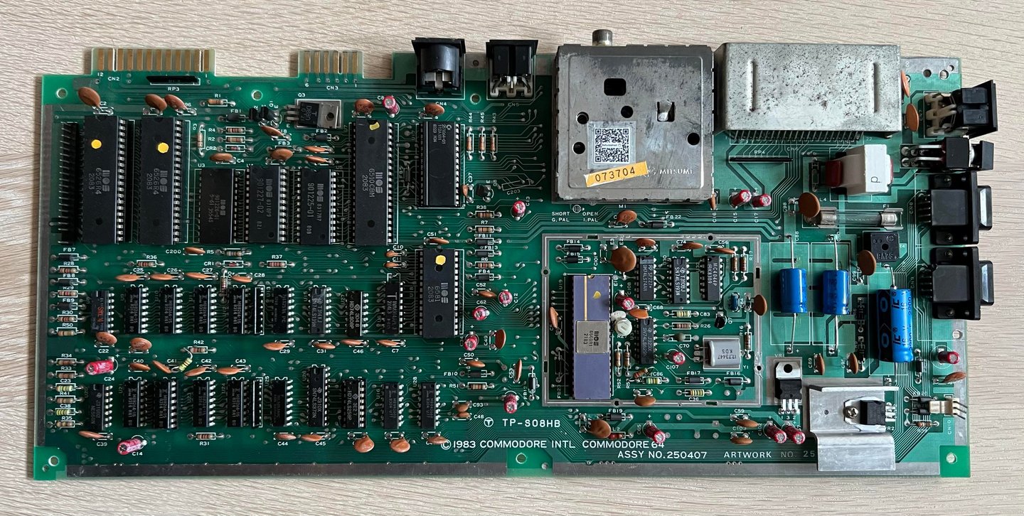
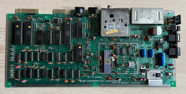
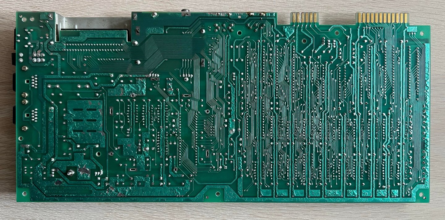
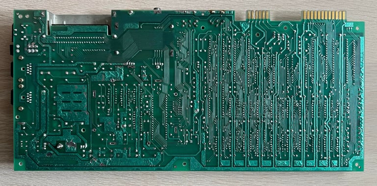
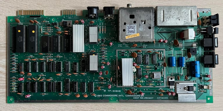
This is an "Assy 250407 / Artwork 251137 (Rev B) / TP-S08HB" long mainboard with the good old 6581 SID, 6510 CPU and 6569 VIC-II chipset. At first glance this mainboard looks to be in good condition. The mainboard is quite dirty so I clean it first with soap water and a soft paint brush. Before cleaning the SID chip, RF-modulator shield and the VIC-II RF-shield are removed. I let it try for a couple of days (while also spraying isopropanol on the board). In the pictures below are the front- and backside of the mainboard after initial cleaning.

Visual inspection
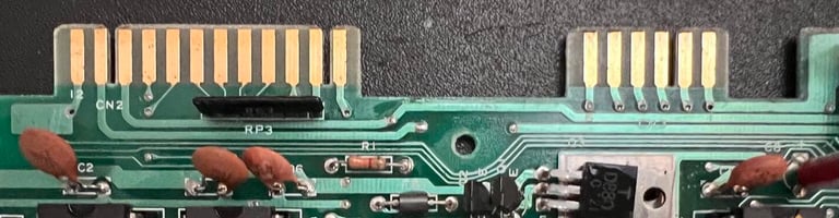
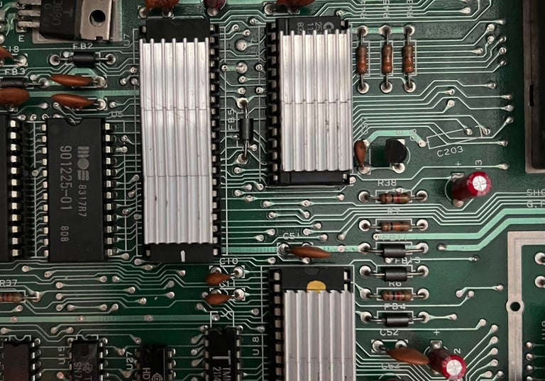
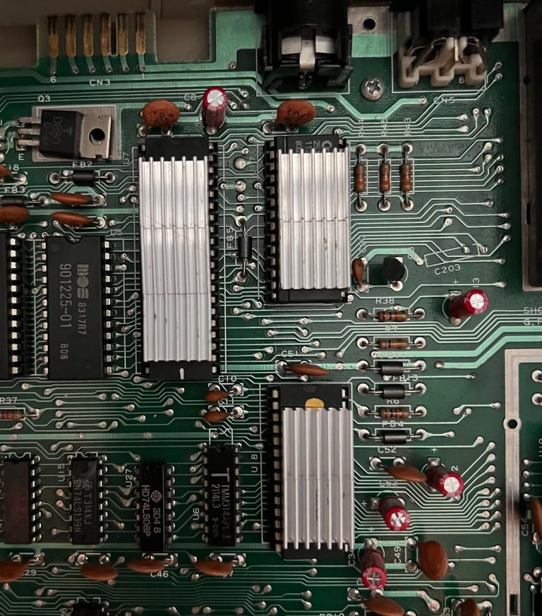
This mainboard looks to be without any damage as far as I can see. There are no sign of corrosion, ripped traces or any bodge wires. There is a bit odd looking resistor soldered to the board from R42 to C41 (see picture below), but I think this is from factory. A last minute change by Commodore? The reason why I think so is that I have seen this before on a similar refurbished mainboard.
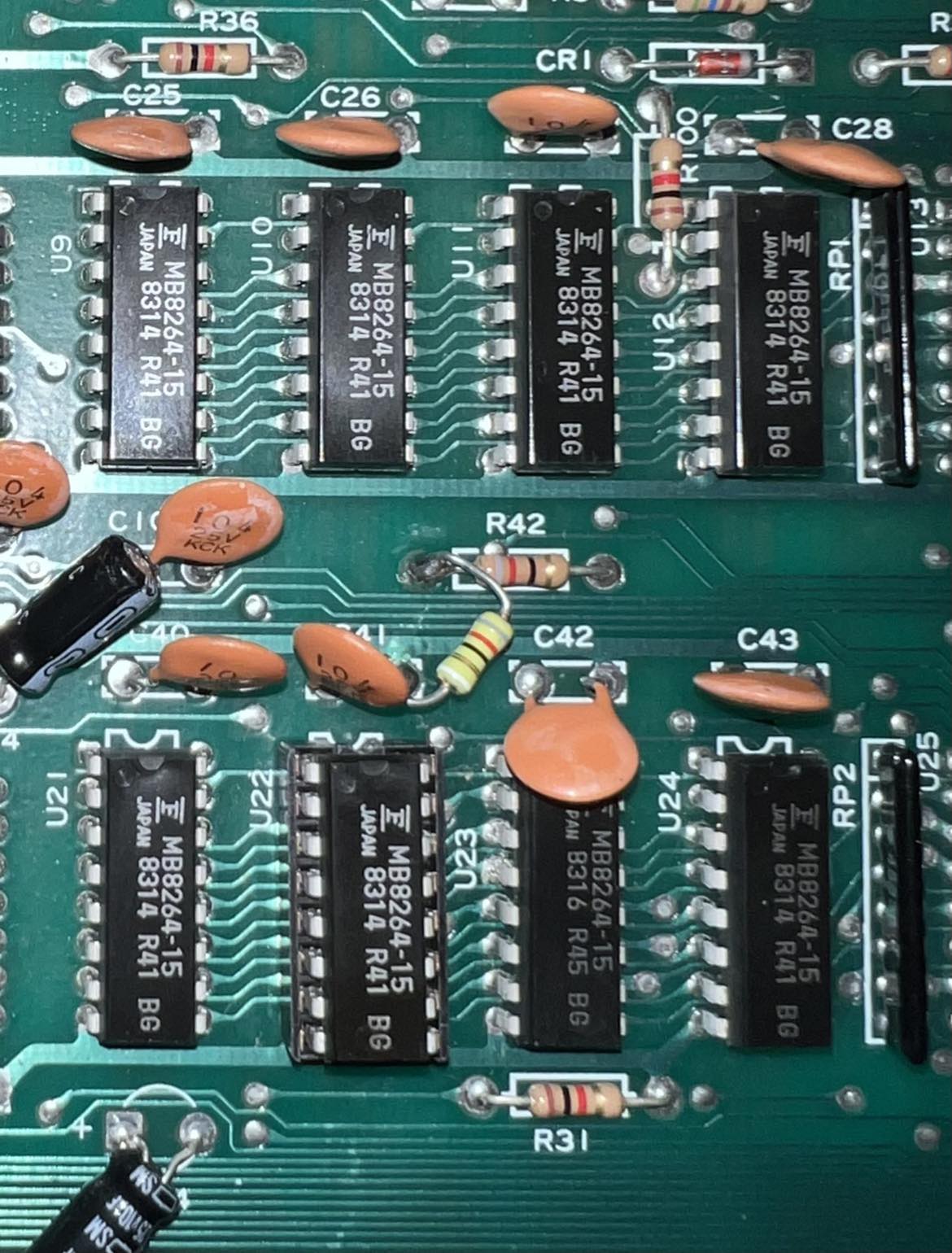
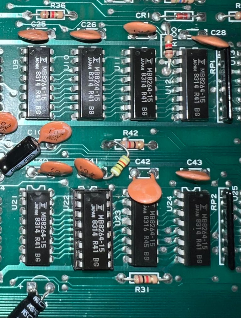
Something else can also be seen from the picture above; U22 RAM chip has been socketed. My theory is that this RAM chip was detected faulty at production time and then replaced (and socketed). Notice that that the date code on these RAM chips are almost identical (differ by a couple of weeks only) so I guess they just replaced it with a new RAM chip at factory.
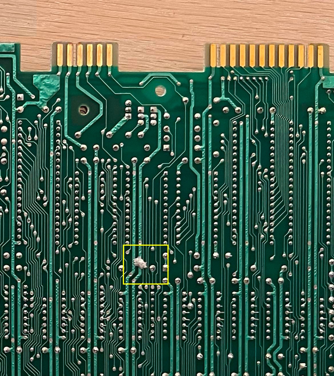
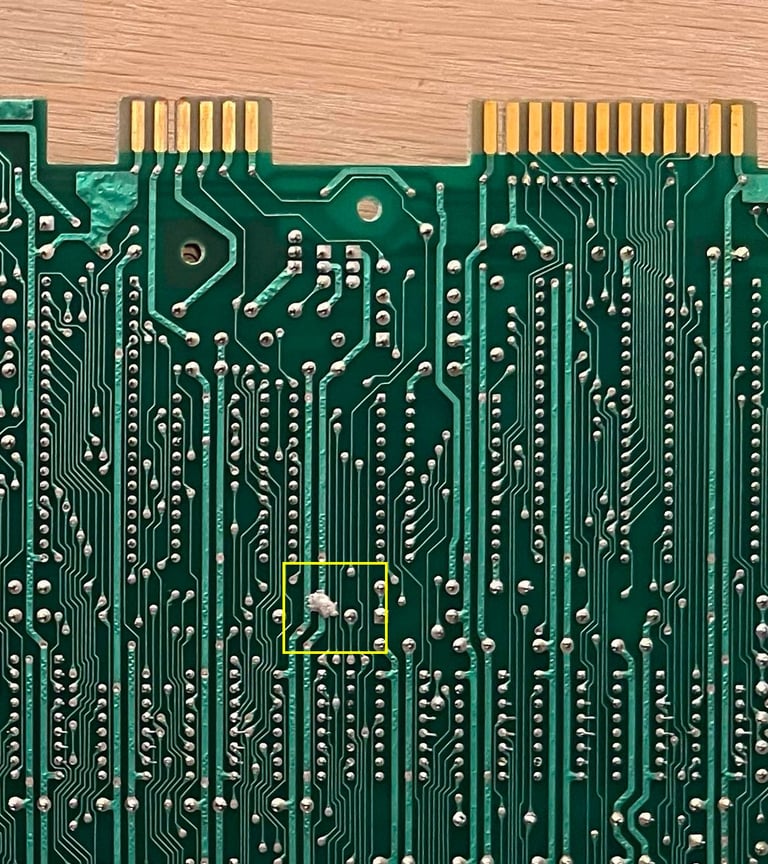
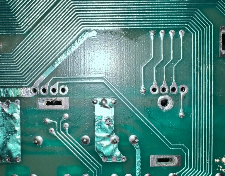
What? Is? This? How could I not see this in the first place? There is a quite large solder blob on the backside of the PCB. Was this from factory? The blob does not seem to short circuit anything, but come on... this does not look right! I need to remove this when refurbishing. In the picture below the area with the blob is zoomed (yellow square).
Several of the chips are socketed which is nice. The sockets were probably installed in the factory - I have seen this on other C64s produced about the same time and the same revision. In the table below the main chips are listed (before refurbishment - some may be changed during repair if required).
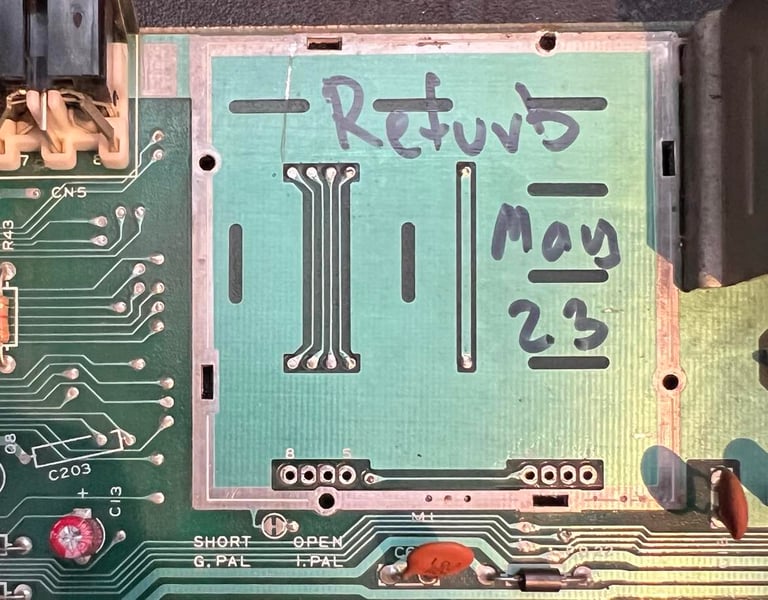
My guess is that this Commodore 64 was manufactured sometime during the summer of 1983. The latest date code is week 23 of 1983.
Initial testing
Before power on I check that there is no short circuit either in the 9V AC or 5V DC lines. This is an easy, and highly recommended, test to make sure your modern power supply is not damaged due to a short circuit on the mainboard. To check for a short circuit in the 9 V / 5 V I check this on the user port. Please see my article ´Checking the Commodore 64 voltages´ (chapter "Measuring the voltages - where?") for details on position of these on the user port.
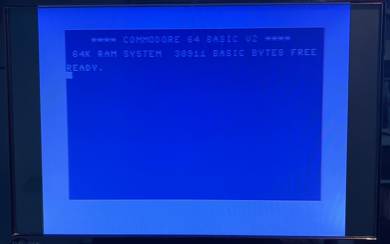
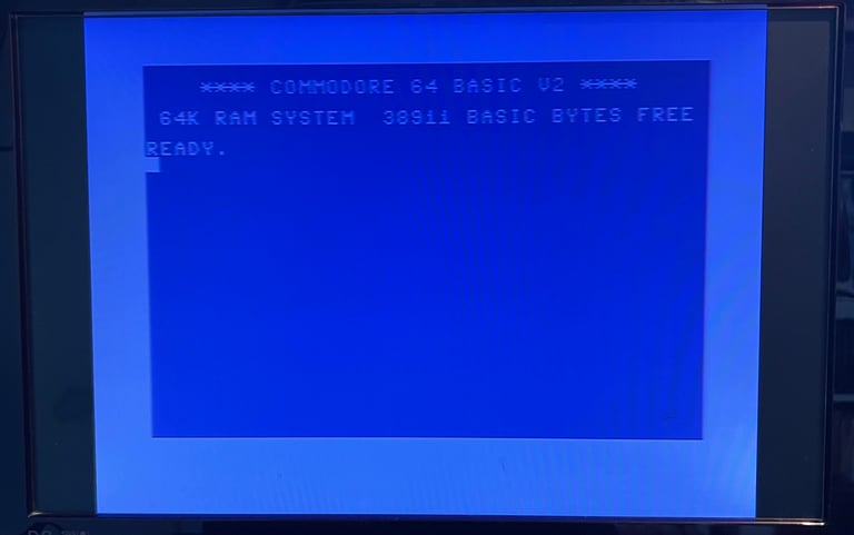
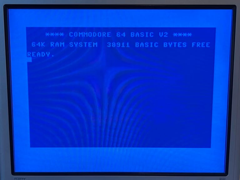
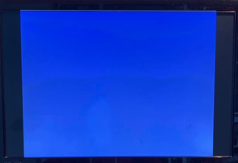
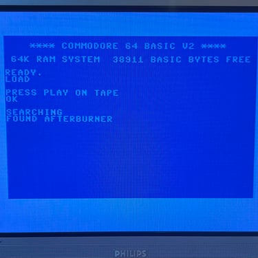
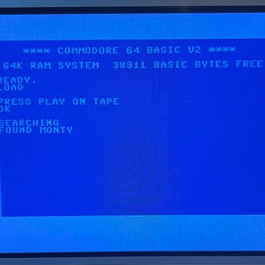
There is no short circuit as I can see so it should be safe to power on for a first test. And SUCCESS the machine boots up with the well known blue Commodore 64 38911 BASIC BYTES FREE screen.
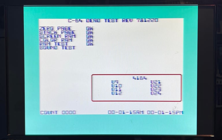
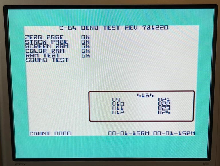
Also the Dead Test Cartridge is used for an intial testing. All checks come out OK here also - and the SID also sounds ok so far. Note; a check with the Dead Test does not imply that everything is working. But it gives a good indication that the main chips are OK.
Voltages
Voltages are measured before - and after - refurbishment. This is to make sure that all voltages are within acceptable levels. This table is updated after refurbishment is completed. All voltages are measured according to the article Checking C64 voltages. As seen in the table below all voltages are within acceptable levels, but I think they are a bit on the low side. A slightly low voltage does not need to have any impact on the machine - but they could also cause some marginal faults e.g. in CIA chips. It will be interesting to see if some (or all) of these voltages increase slightly after refurbishment.
Cleaning the power switch
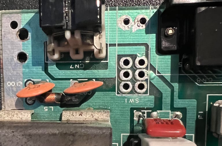
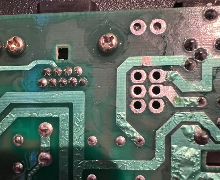
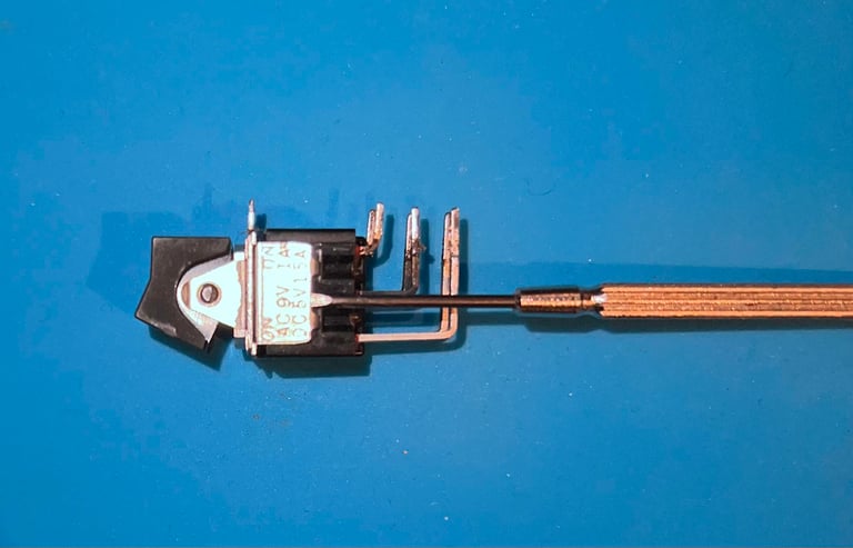
It is not unusual that a Commodore 64 is not working only because the power switch (SW1) is dirty. Over years dust and grease gathers up inside the switch preventing it from conducting either/or both the 5V DC and 9V AC. As a preventive measure it is a good idea to clean the power switch. The metal bracket on the right hand side of the mainboard is removed (there are two screws holding it in place) and then the power switch is desoldered. As can be seen in the pictures below no pads or traces were lifted during the desoldering. Note; it can be a good idea to use both a soldering iron and desoldering gun while doing this. While the soldering iron is heating from the topside of the PCB the desoldering gun is removing the solder from the backside.
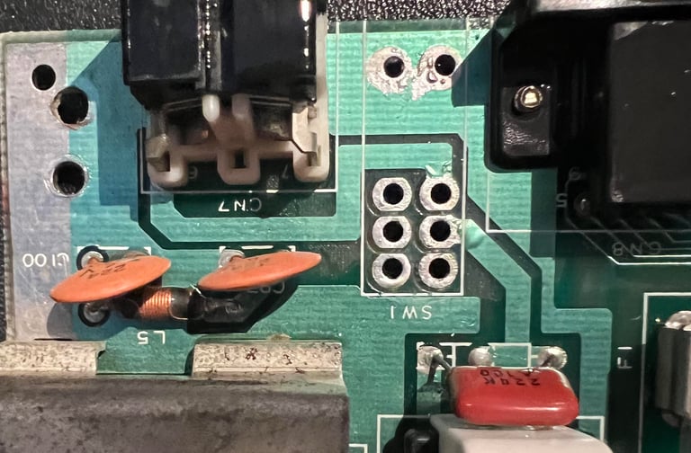

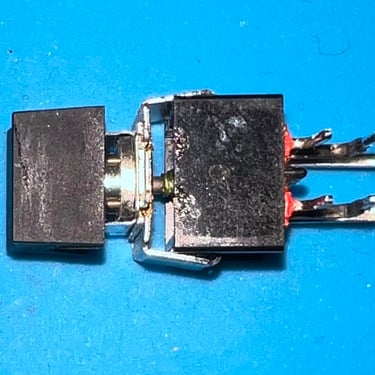
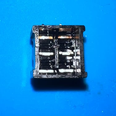
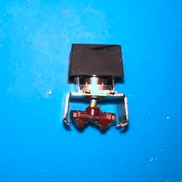
The switch is carefully opened by lifting the metal bracket on both sides with a small flat screwdriver. See picture below.
Each little part of the switch is cleaned with isopropanol. See picture gallery.
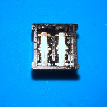
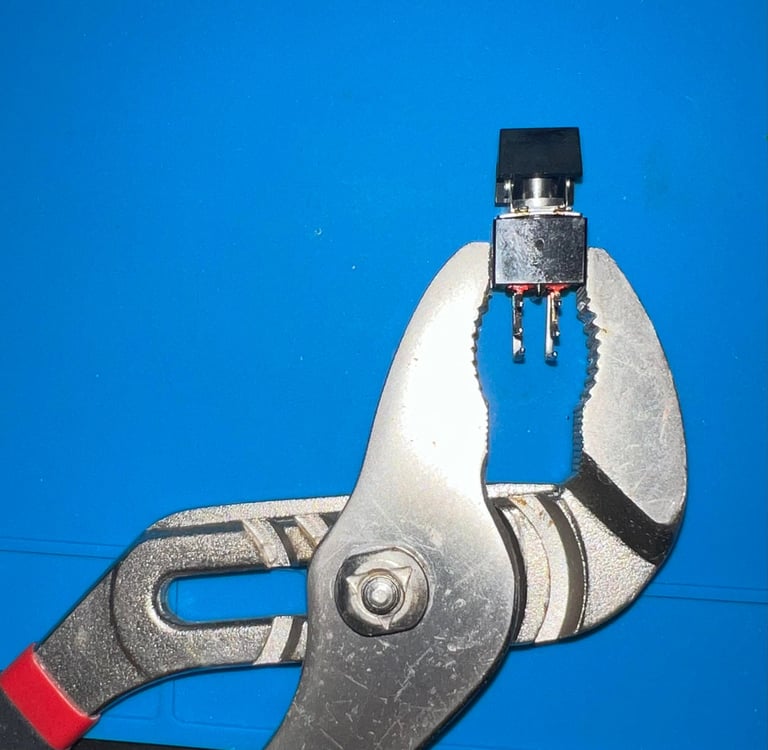
Finally all parts are assembled and I use a pipe wrench to clamp the metal bracket back in place.

A helping hand
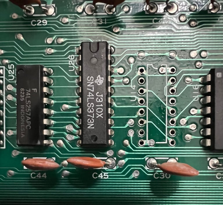
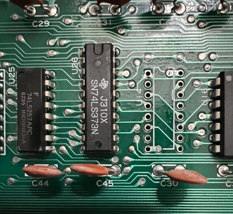
While repairing another Commodore 64 (Ser.No. 828599) I need to borrow a 74LS258 chip (U14). So, I desolder and socket the chip from this Commodore 64 and borrow this chip for a minute to see if this was faulty on the other machine. No traces or pads were lifted.
Replacing the electrolytic capacitors - Mainboard
All 18 electrolytic capacitors on the mainboard are replaced according to the capacitor list for this revision. I use only quality capacitors from Panasonic/Vishay and Wurth Electronics. Note: the 470 uF capacitors were originally rated to 50 V which is not necessary - 25 V caps are used instead. In the picture below all the new capacitors on the mainboard are in place.
Removing the VIC-II area RF-shield
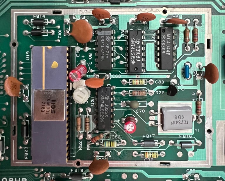
There is a RF-shield surround the VIC-II area. This RF-shield is no longer relevant in modern times. It will only encapsulate heat and is also makes it more difficult to remove the RF-modulator later (hard to get the tools passed the RF-shield). The picture below shows the VIC-II area when the RF-shield is removed.

Replacing the electrolytic capacitors - RF modulator
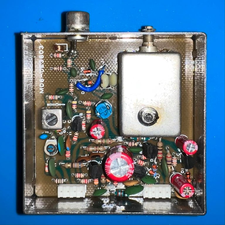
This is a RF-modulator from Mitsumi (MD6-UE3603) containing four electrolytic capacitors. But to replace the capacitors the RF-modulator first needs to be desoldered which is not a trivial operation. Use a combination of desoldering gun, soldering iron and hot air to remove the module from the mainboard. No traces or pads are lifted during the desoldering operation (see pictures below).
New electrolytic capacitors from Wurth Electronics are used; 1 x 10uF [16V], 2 x 100 uF [10V] and 1 x 470 uF [10V].

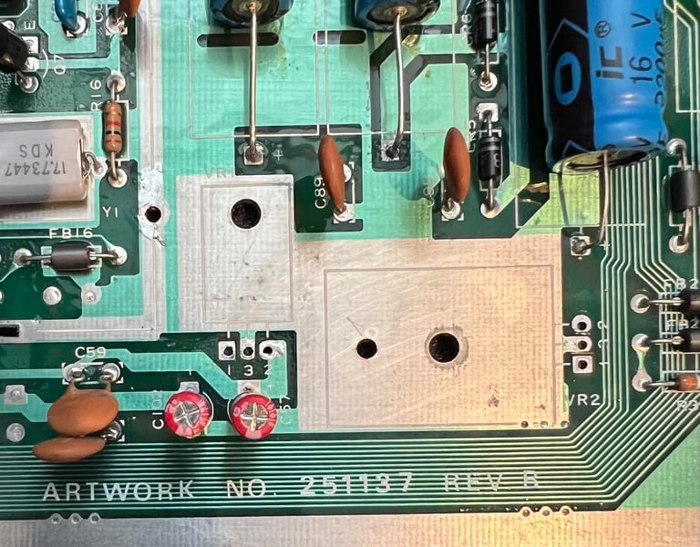
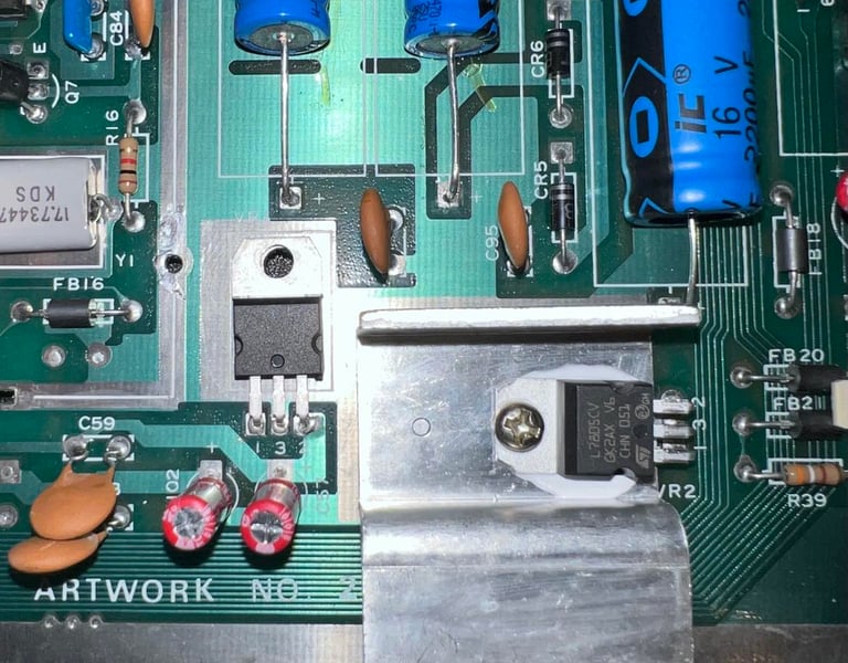
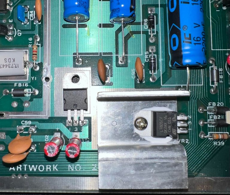
Replacing the 5 V- and 12 V voltage regulators
In addition to the 5 VDC and 9 VAC coming from the powersupply (PSU) a 5 VDC and 12 VDC are generated inside the Commodore 64. These two additional voltages are sourced from a 7805- and a 7812 voltage regulator. See the article about voltages within the Commodore 64 for further details.
Both voltage regulators are desoldered and no pads/traces were lifted. New regulators are soldered back in. Note that it is only the 7805 (5 V) regulator which is mounted on a heat sink. This is normal. Also, a small drop of heat paste is placed between the voltage regulator and the heat sink. See pictures below.
Cleaning the user- and datasette port
Both the user- and datasette port are cleaned with first with a rubber eraser and then isopropanol. It is crucial that these contacts are clean to make sure they operate as they should (e.g. loading a game from cassette).

Adding heat sinks
Some of the major ICs of the Commodore 64 can get quite hot and heat could catalyst the deterioration of a chip. Therefore heat sinks are placed on some of the most important ICs; SID, VIC-II, CPU and PLA. Even though most of the heat still is still transferred trough the IC pins soldered to the board the heat sinks will assist in the heat transfer from the IC package to the surround air.
In the pictures below the now completely refurbished mainboard is shown - both before and after heat sinks are added. All voltages are measures again and the voltage table in the beginning of this chapter is updated.

Testing
Testing is done through two main stages:
Testing the basic functionality and chips
Testing by using the machine playing demos, games etc. to verify correct operation
Basic functionality and chips
First test is done using the Dead Test Cartridge. This test doesn´t test all the functionality of the Commodore 64, but it does test the basic functionality of the major chips such as the CIA #1/2, CPU, VIC-II, PLA, RAM and SID. As the picture shows below the test is passed.

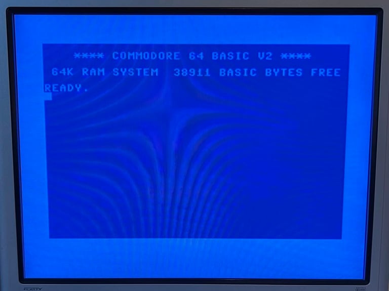
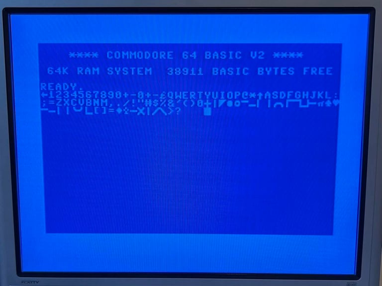
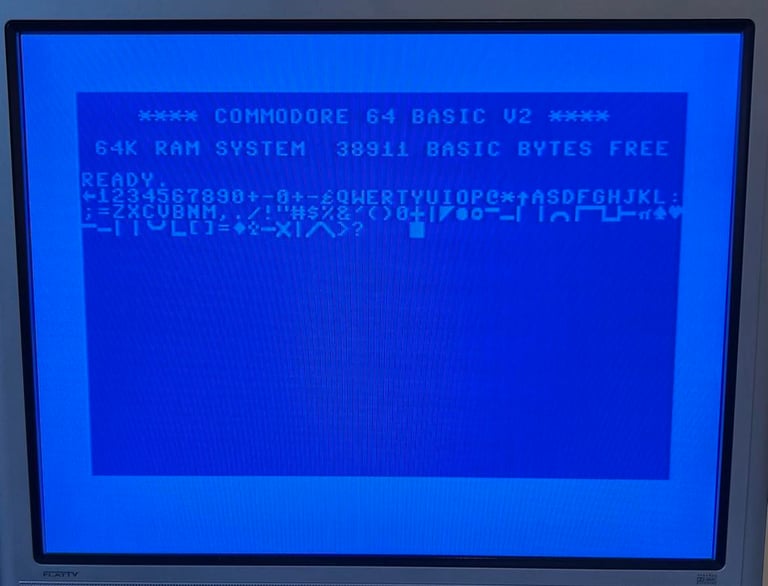
Next test is to power the Commodore 64 to the blue boot up screen and also check the keyboard to make sure all keys works as they should. The test is passed; all keys works and 38911 BASIC Bytes Free.
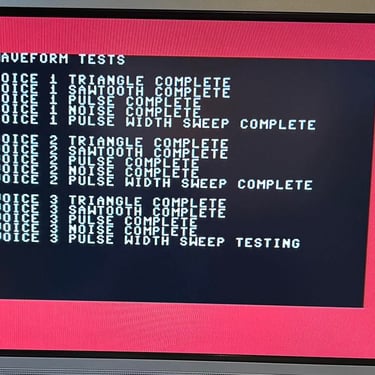
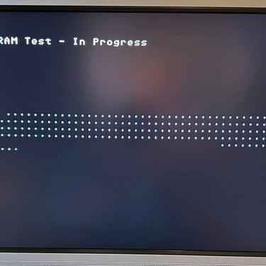
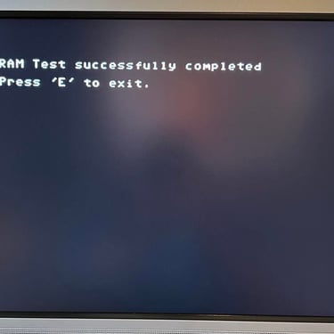
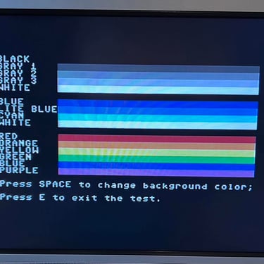
The basic functions of the VIC-II, SID and RAM is tested with 64 Doctor. Note that this is to be considered as basic functionality - more advanced (?) functionality such as sprite handling / collision detection / advanced audio will be tested later. But the basic tests pass without any detected faults (click to enlarge).
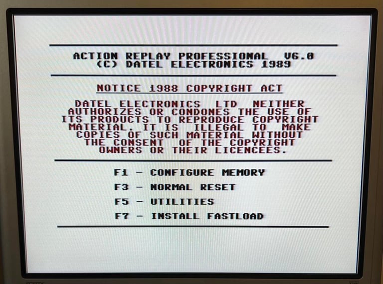
Last basic check before moving to more extensive testing is checking the cartridge. This is done by using the Action Replay VI. Result is that the test is passed.

Extended testing
SPOILER ALERT: FAULT DETECTED!
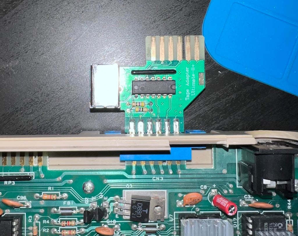
The purpose of the extended testing is to make sure that the Commodore 64 works as expected. To do this I use the Ultimate 1541 II+ which emulates both floppy drives, datasette, REU etc. I quite rapidly see that when everything is connected (that is Ultimate 1541 II+ with tape adapter) the machine gives a black screen. I quickly see that this is caused by the tape adapter.
But the strange this is that when I test with a real datasette the Commodore 64 works as it should. So is something that only happens when the Ultimate II+ tape adapter is installed. Nevertheless, this needs to be fixed!
Repair
Although it is annoying to find faults this late in the process it shows the importance of the extended testing. This fault would not be detected with only checking the basic functionalities.
First, I check that the UII+ tape adapter works with other machines. And it does. So this problem (black screen) is related to the current Commodore 64 in testing.
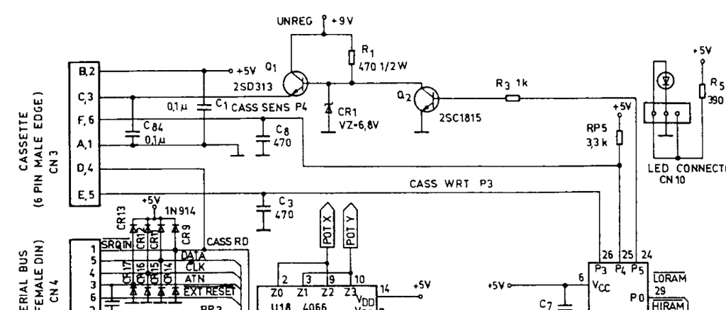
Below is a schematic of the datasette port input. As can be seen there are only six ports connecting the datasette to the machine.

The voltages on the datasette port are measured. They are measured both when the UII+ tape adapter and a normal 1531 C2N datasette are connected for comparison.
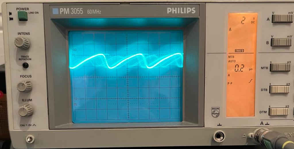
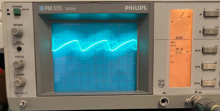
WRITE signal on PIN # 5 is really bizarre when the UII+ tape adapter is installed. As seen from the picture below the signal seems to be oscillating with a quite high frequency (about 1.4 MHz) between 1.8 V - 4.2 V. This is clearly not any normal digital signal.
As seen from the schematics above PIN#5 is connected to PIN #26 on the 6510 CPU. Only a capacitor on 470 uF (C3) connected to GND is between. I know that the tape adapter works in other Commodore 64s, so could the fault be caused by the C3 or the CPU? To test this I move the CPU to another Commodore 64 with the same PCB and try the UII+ tape adapter. Same result - black screen. So this does show that the CPU is in fact marginal - it works 99 %, but there is something odd happening when a UII+ tape adapter is connected.
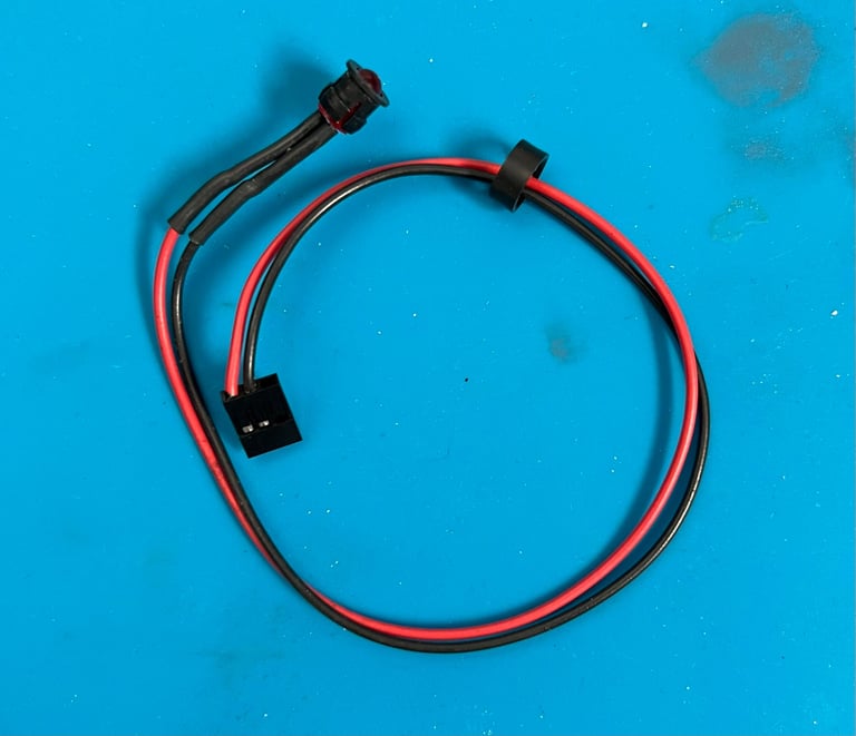
You could argue that this is not a real problem. The machine would work with ordinary 1531 C2N datasette, but I would like it to work with "all" C64 peripherals - including the Ultimate II+. So I order a new CPU from retroleum.co.uk. Below is a picture of the Ultimate II+ tape adapter when installed.

When you need advice ask for help! I am struggling understanding what is happening here so I post a message on Facebook in the Commodore/Amiga Norway group and get reply very quickly from the person behind the highly recommended YouTube channel KOJRO Retro innovations. He points me in the direction of checking further that the 1531 C2N datasette actually works in this Commodore 64 which I claim it does. The suggestion is to try to activate the WRITE function from the CPU to the datasette and see if this works. And it turns out... it doesn´t. So this problem is not only - as I first thought - relevant for the UII+ tape adapter, but it is relevant for all 1531 C2N datasette also when trying to write to this.
It could be that the CPU is broken due to static electricity which was quite common in the 80s. And I think he describes this scenario just fantastic - and it so makes me remember my own childhood:
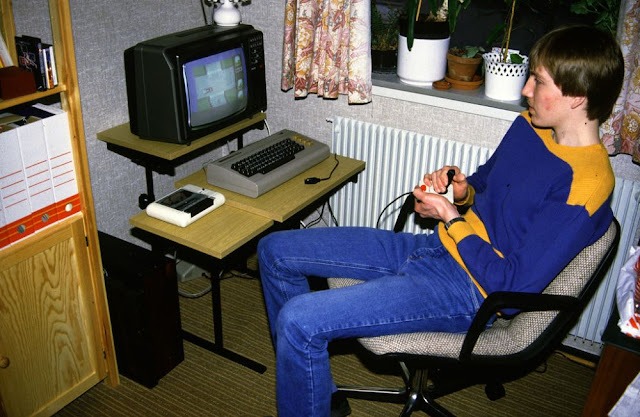
"Arne Harstad, have you tried saving something to tape on it with a normal C2N? Write is normally only active if something is written. Yes, those who remember the 80s with high-static carpet floors and C64 lying in a pile in front of the TV in the living room or basement, full of kids who rubbed themselves into the carpet with thick Ball or PocoLoco sweaters while switching between cassette players that were calibrated to exactly that the turbo tape realizes that here there was a lot of high voltage and static electricity."
To get into the 80s mood check out "20 Vintage Photographs of People With Their Commodore 64, One of the Most Beloved Home Computers of All Time" - picture below is from that collection.
So I just need to wait for a replacement CPU to arrive. The old one was not 99% marginal as I thought, but more like a 80 % since writing to a datasette is a bit more than a "nice to have" feature.
The author behind KOJRO Retro innovation made a YouTube video inspired by my post on Facebook (Commodore/Amiga Norway). I highly recommend watching this video as he is an expert on Commodore 64 service and repair. Check the video in the link below.
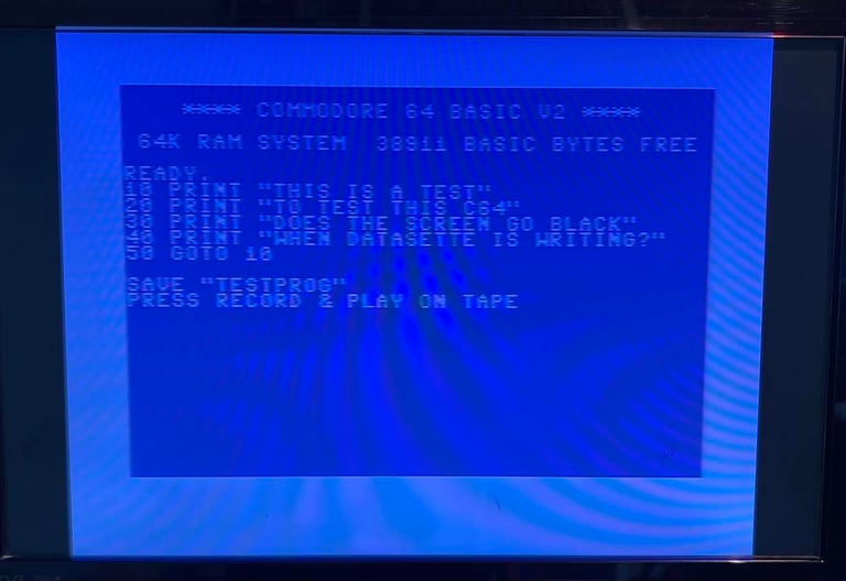
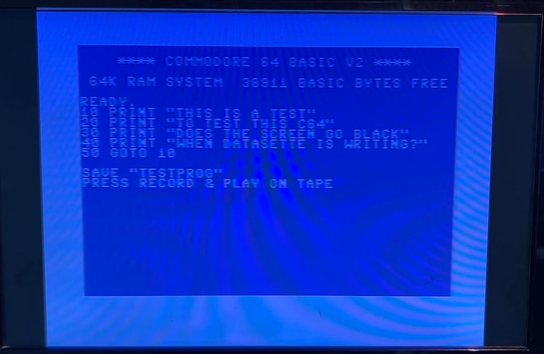
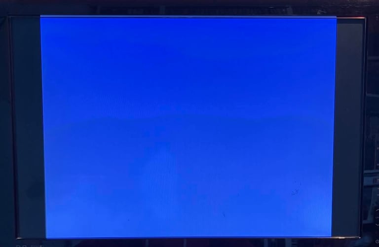
Below are pictures from the short test program which I wrote and tried to SAVE to a tape. The program, saving and tape works fine on other C64s, but on this C64 it only gets "stuck" in a blue screen. Nothing happens. It does not produce a black screen as the tape adapter, but it does not work nonetheless.

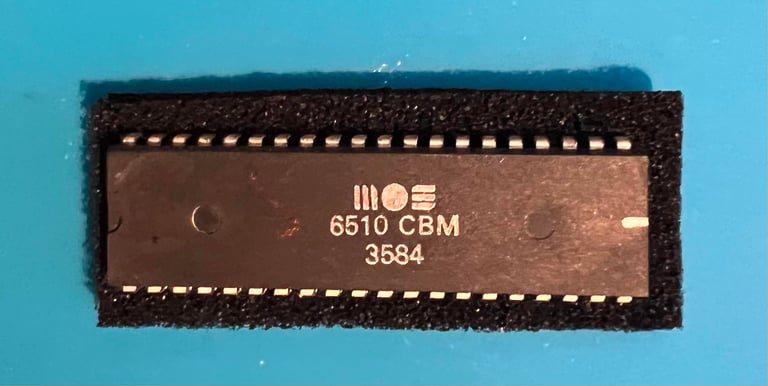
A "new" MOS 6510 CPU arrives from retroleum.co.uk - and even if this is an old chip it is still younger than the rest of the MOS chips on the mainboard. This one is from week 35 in 1984.
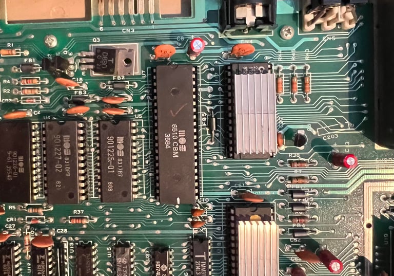
The new CPU is installed and a heat sink is placed on its top. Its time to continue with the extended testing.


Testing - continued
Extentended testing
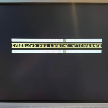
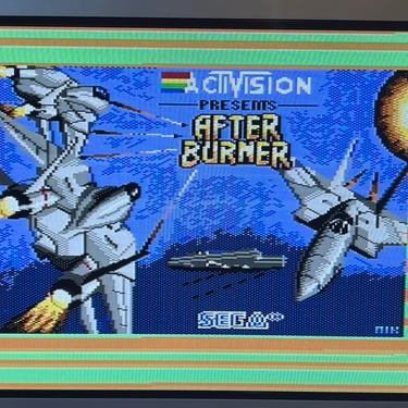
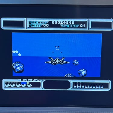
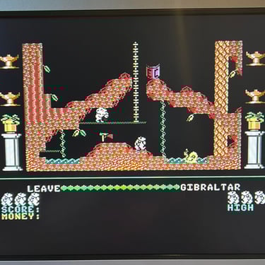
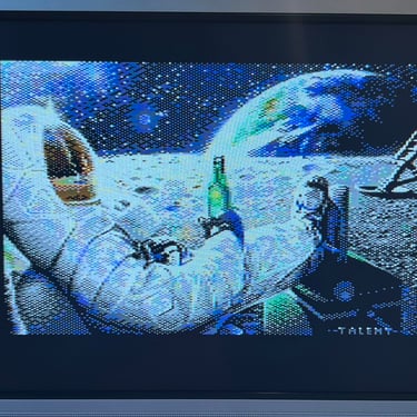
The machine is retested for basic functionality as before, but the main focus now is in the extended testing. And the result is that everything seems to work very well. I can not detect any issues in normal operation. Loading both from tape and floppy works fine, no audible problems from the SID chip and the VIC-II video chip is also working as it should.
I play several games and check a variety of demos; none of them show any sign of issue. So my conclusion is that this machine now works as it should.
Below are some pictures from the testing (click to enlarge).


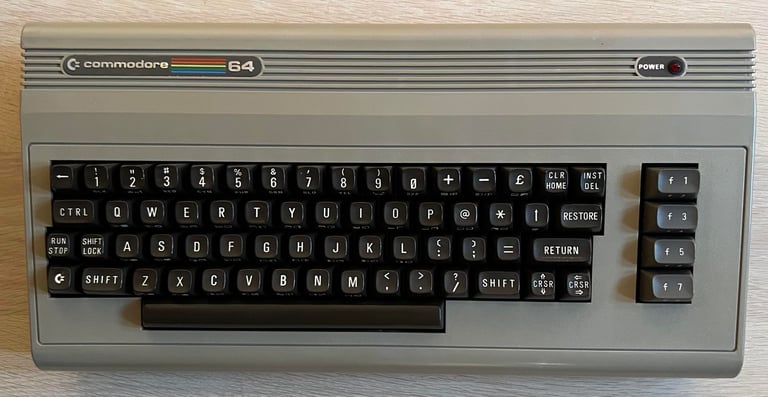
Final result
"A picture worth a thousand words"
Below is a collection of the final result from the refurbishment of this C64. Hope you like it! Click to enlarge!


Banner picture credits: Evan-Amos