

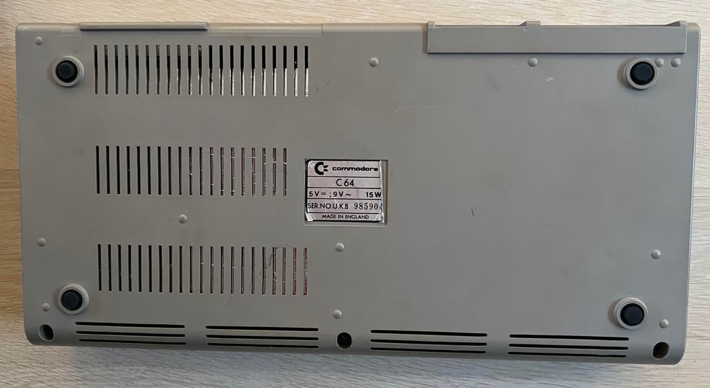
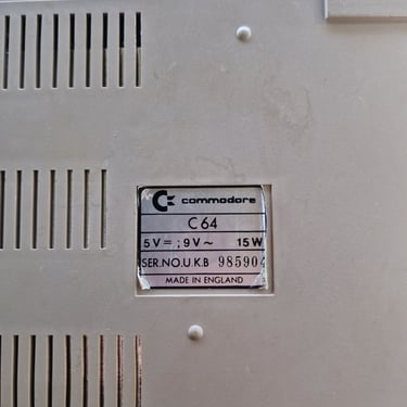
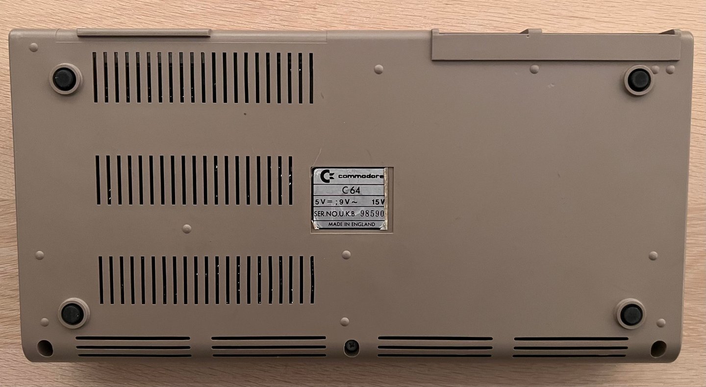
C64 Breadbin [PAL]
Ser. No. 985904
Assy 250407
Artwork 251137 (REV C)
Starting point
I was contacted the other day and asked if I would like to purchase an untested Commodore 64 for a fair price. The seller would like to see that someone interested to take care of this machine and also happy to help me on supporting the Norwegian Childhood Cancer Society (Barnekreftforeningen) So, yes, a good win-win situation there. Thanks!
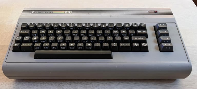
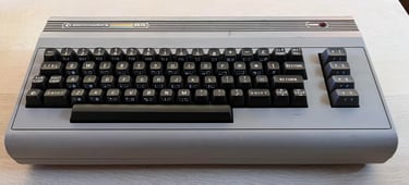
Below are the pictures I received from the seller. This could be a fun project!
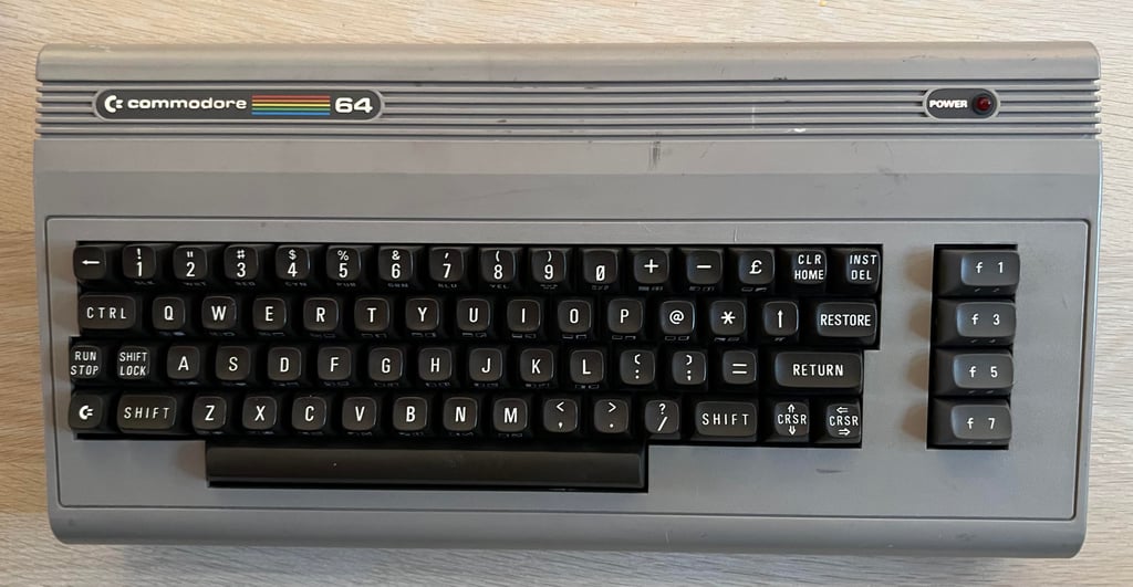
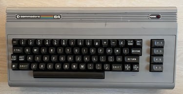
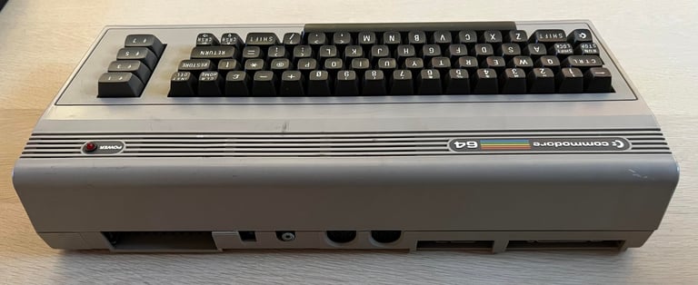
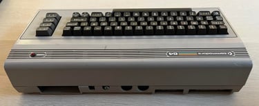

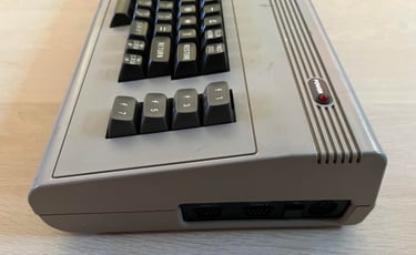
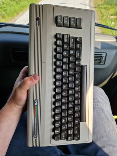
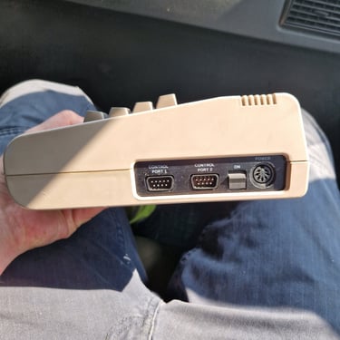
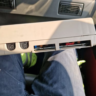
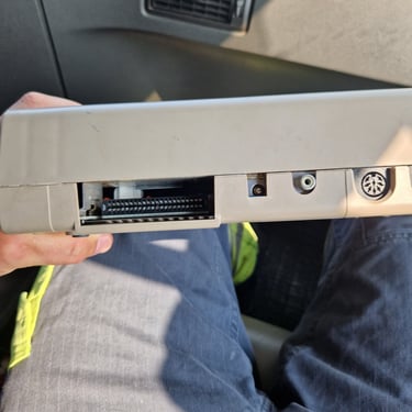
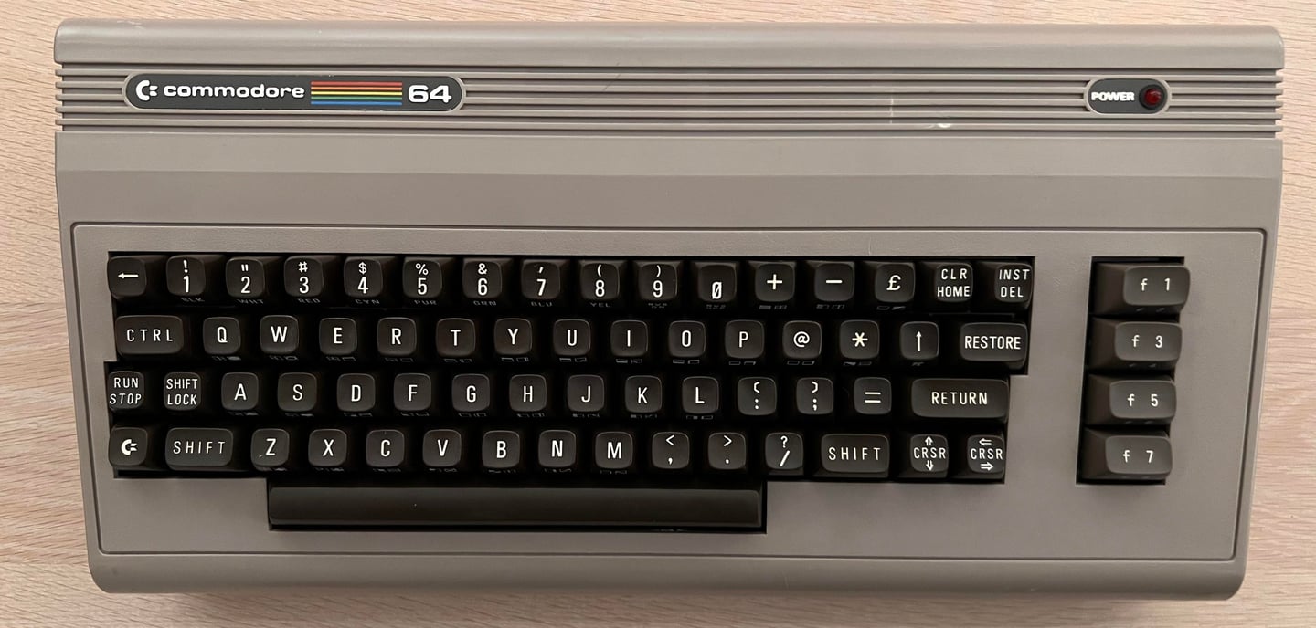
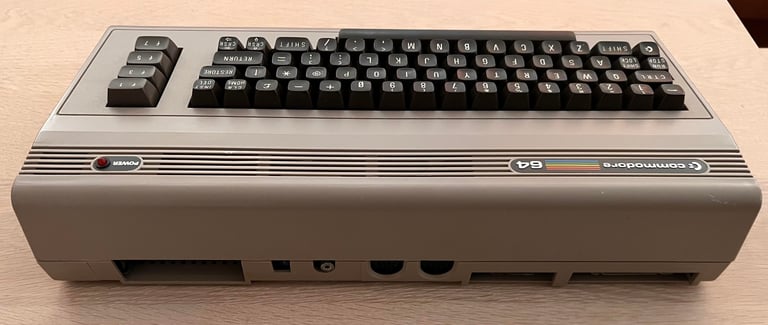
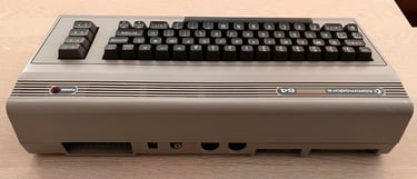
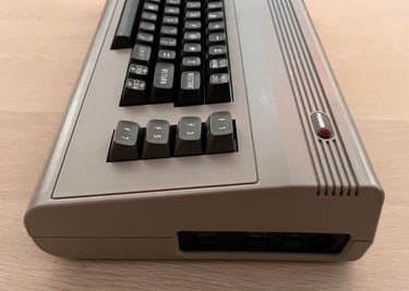
The Commodore 64 is received well packed without any damage during the shipping. Below are some pictures of the machine before refurbishment commence.
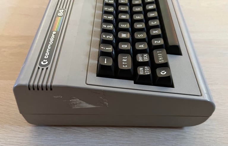
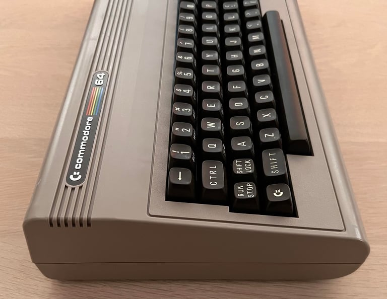
From the outside the machine looks to be in quite good condition. There are some marks from usage and stickers of the top- and bottom cover, but I belive this can be fixed with some love, car and tenderness (read: some hours of good cleaning).
The machine has been opened previously some time in the past as two of the three screws holding the covers together are missing. Again, should be easy to replace. I can not see any damage to the cover/chassis otherwise.
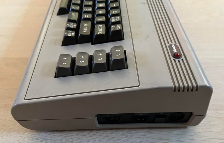
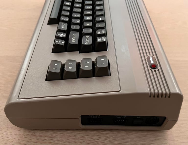
But the power switch seems to be broken. This is not uncommon for the old Commodore 64. I can toggle the switch from ON/OFF position, but I feel with my fingers that there is something wrong with this. I will probably try to service this switch myself (like I did with this C64 breadbin), otherwise I need to order a new one.

Refurbishment plan
The refurbishment plan for this C64 breadbin (order can vary and some of the tasks will be done in parallell):
- Clean and remove stains from the chassis
- Clean and restore the keyboard
- Repair power switch
- Refurbish main board (cleaning, checking, repairing, replacing capacitors and voltage regulators etc.)
- Recap RF-modulator
- Verify operation by testing
The plan can be updated during the refurbishment process. Sometimes I discover areas that needs special attention.
Exterior casing
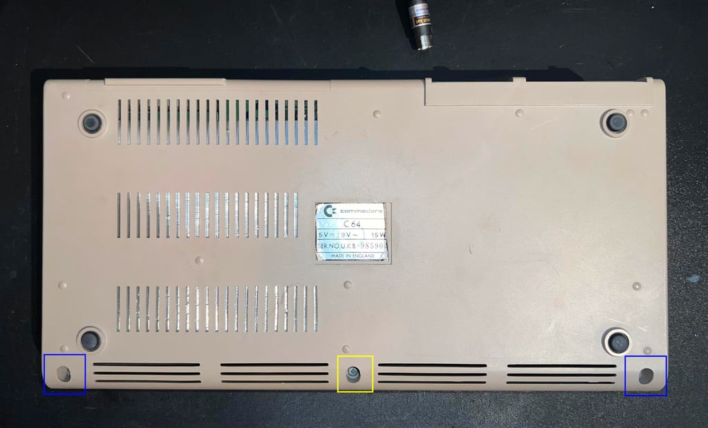
As mentioned in the "Starting point" chapter the top- and bottom cover looks to be in good condition. I will require some good cleaning to get all the dirt off, but hopefully the marks are only skin-deep. To clean the casing the two covers are separated. This is done by removing the three screws at the bottom, but since two of these are already missing this is done by just removing the last remaining screw :-) As seen in the picture below: the yellow square is where the single screw is and the two blue squares where the two missing screws should be.

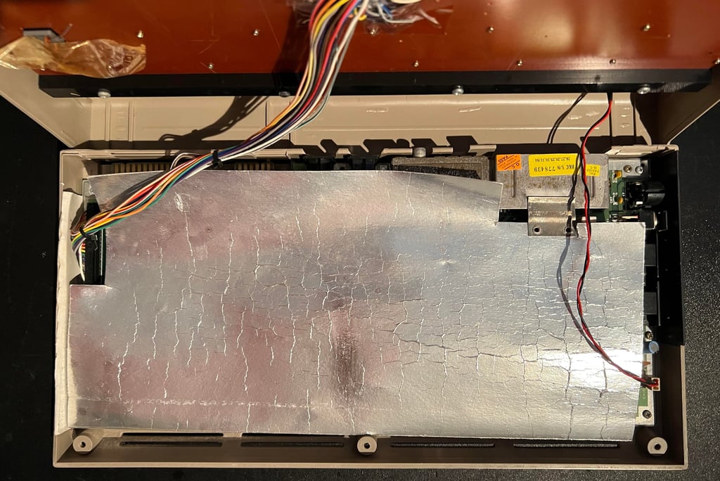
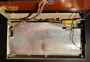
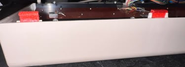
The top cover is carefully removed. When opening the top cover it is good practice to only lift this about 30 degrees and then "wiggle" the cover off. This can potentially avoid breaking the fragile brackets at the rear of the top cover. Removing the top cover reveals the inside. As the picture shows below there is a large cardboard RF-shield covering the mainboard. This shield will be removed (and thrown away) later as it serves no purpose anymore - other than heating the chips inside unnecessary. This shield was part of the old FCC regulations meant to prevent electromagnetic interference. Made sense back in the 80´s, but has no purpose in 2023.
As can be seen in the picture below there are no obvious damage to the machine. Next, the RF-shield will be lifted.
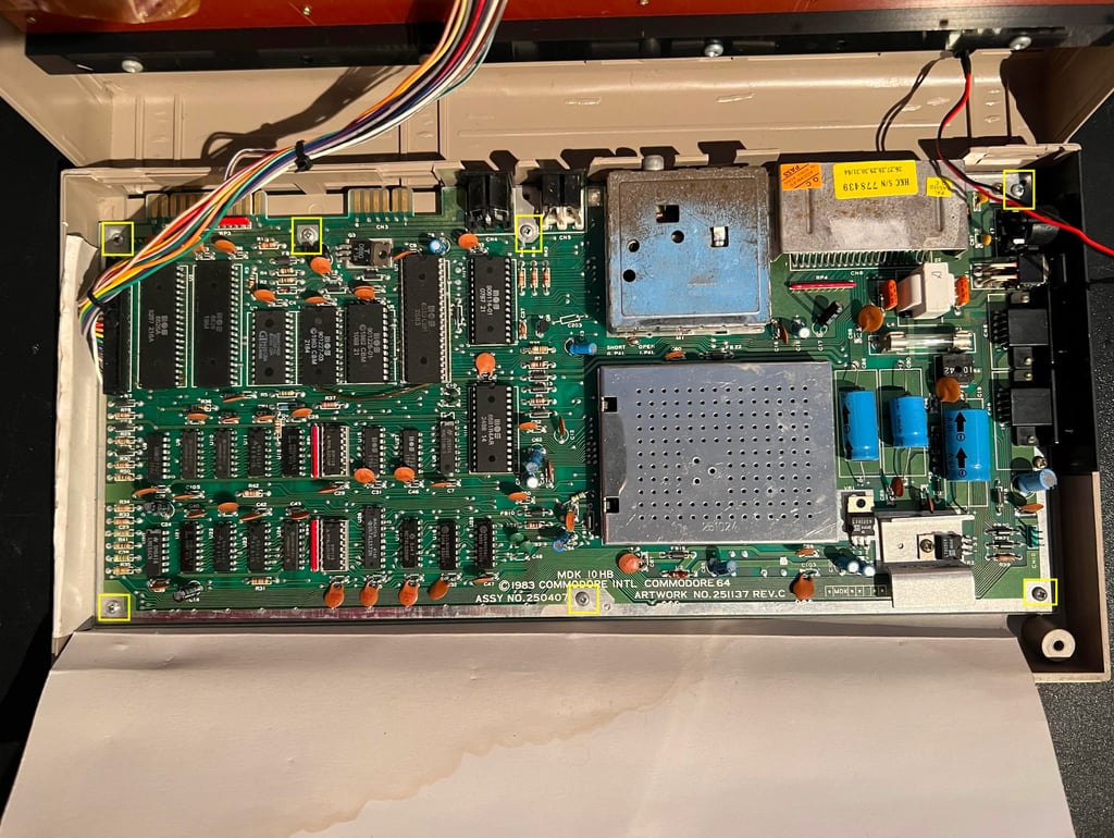
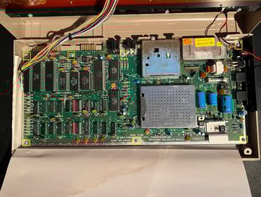
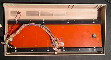
When the RF-shield is removed the mainboard is revealed - see picture below. No missing chips! That is good! And also I can not see any obvious damage to the mainboard. As seen in the picture below there are some signs of moisture in the left side of the RF-shield cardboard. But I can not see any immediate sign of corrosion - I will look closer in the "Mainboard" chapter. The mainboard is freed by first removing the connector to the LED and keyboard, and then the seven screws (yellow squares) are removed.
Although not strictly required it is good practice to remove the power LED. This is done by first removing the small circular outer clip from the backside of the top cover. Now push the LED firmly inwards from the outside of the cover until it pops out. Finally, the inner plastic clip is pushed from the inside and outwards. Below are some picture from the process.
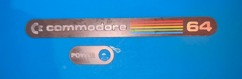
The “Commodore 64” and “Power” badge are removed before cleaning. This is done by adding some hot air from a hair dryer while carefully lifting the badges with a thin sharp knife. After removing the badges are cleaned with isopropanol.
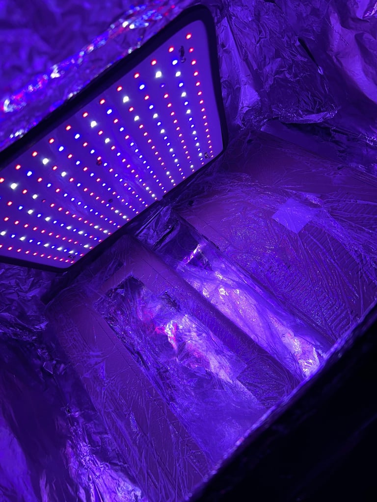
Both the top- and bottom cover are cleaned thoroughly with mild soap water and some isopropanol. All the marks from grease, dirt and stickers are gone after cleaning. The covers are a bit yellowed (but not much) so they are retrobrighted for about 10 hours using 12 % hydroperoxide cream and UV-light.

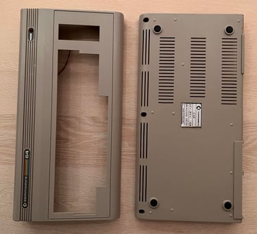
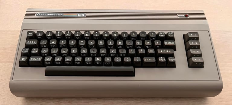
The result of the cleaning and retrobrighting is quite good I think! There are some marks on the top- and bottom cover which are impossible to remove, but other than that it looks very nice.

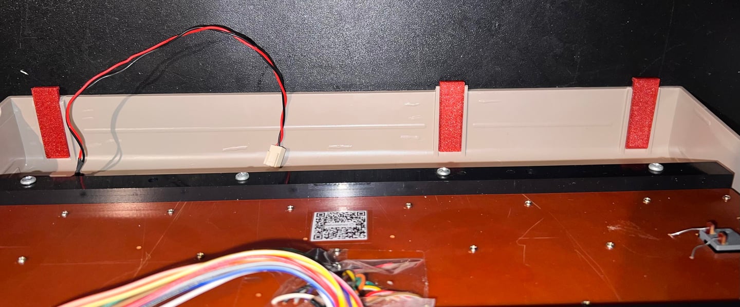
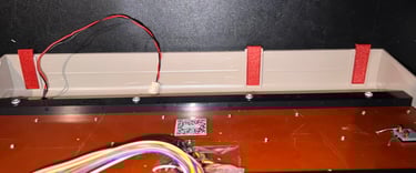
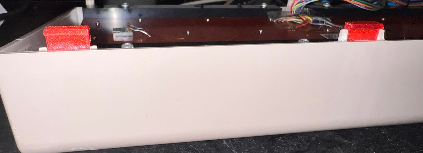
Unfortunately, the rear plastic clips are broken. This is very common on these machines. These plastic clips are old and brittle and break easily. Luckily, it is possible to 3D print new clips which are actually better than the original. New clips can be found at Thingiverse: https://www.thingiverse.com/thing:5916458. Three new clips are 3D printed (in the picture below two of them are shown).
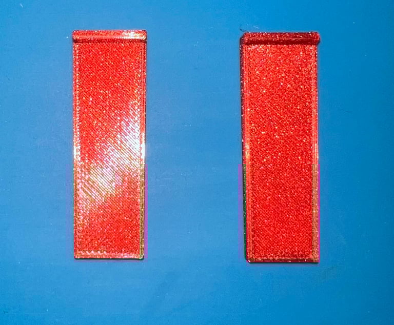

The new clips are measured in place and then glued to the rear of the top cover (and left to dry for about 24 hours).
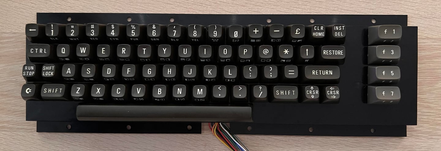
Keyboard
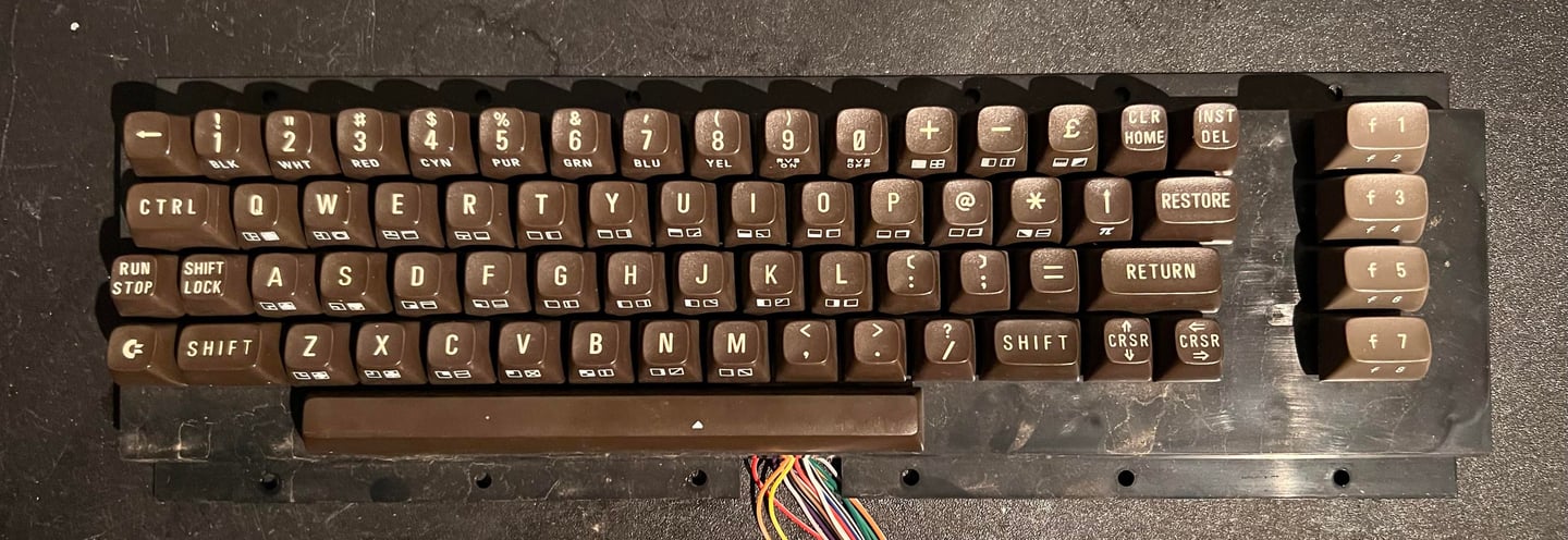
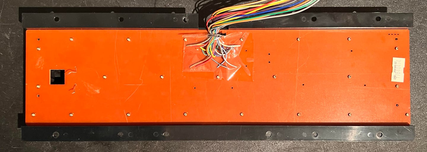
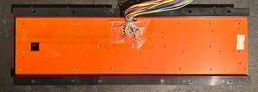
The keyboard is loosened from the top cover by removing the eight screws on the backside. See picture below.

The keyboard looks visually to be in good condition, and all the keys feels ok. I can not see any immediate damage to it. It is quite dirty beneath the keys, but nothing that can´t be cleaned hopefully.
Each keycap is carefully removed using a keycap puller. I highly recommend using this kind of tool to reduce the risk of damaging both the key and the plunger. Note that the spring beneath the spacebar is larger than the rest of the springs. So it is a good idea to place this spring in a separate bag.
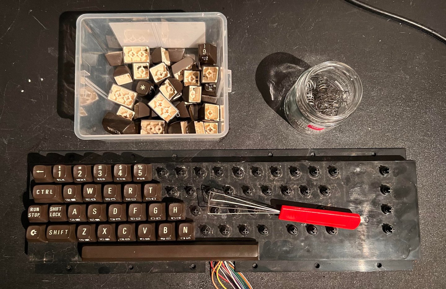
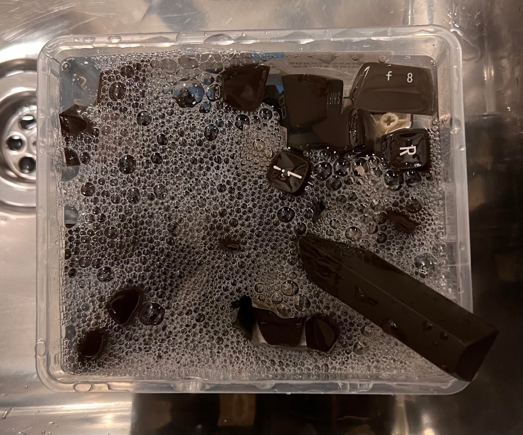
All the keycaps are placed in mild soap water for about 24 hours. This dissolves most of the grease and dirt, and the keycaps looks very nice afterwards.
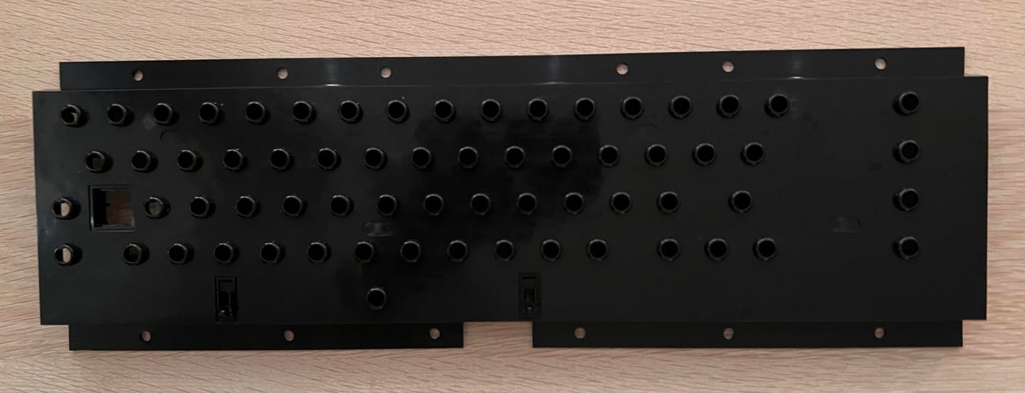
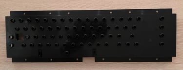
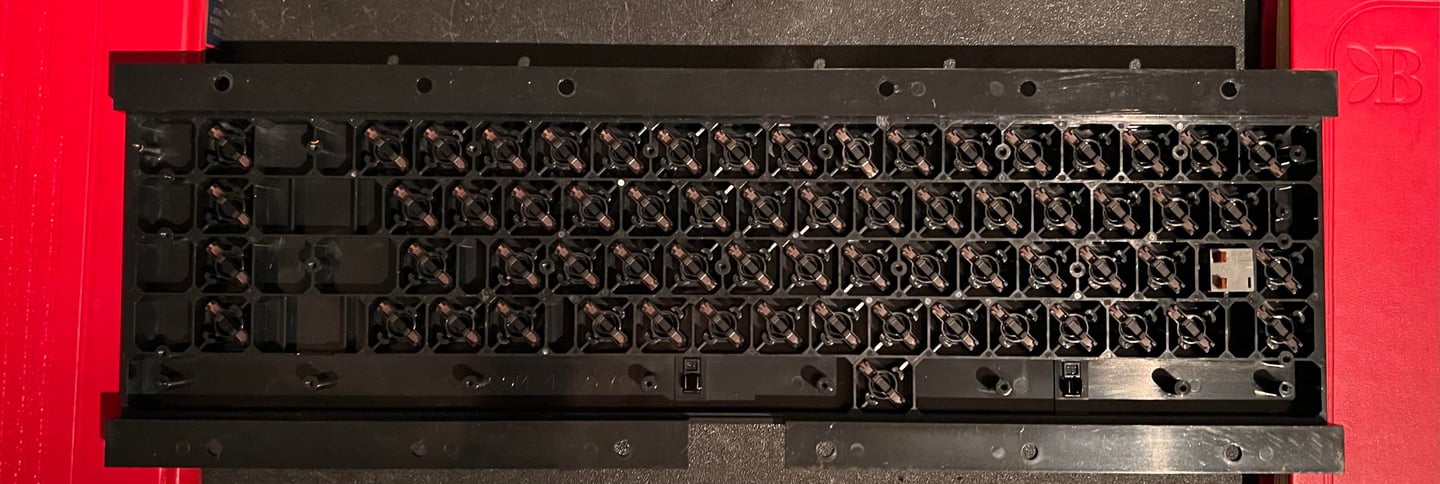
The PCB is removed from the plastic casing (by unscrewing a million small screws). The PCB is cleaned with isopropanol (I forgot to take a picture unfortunately). And the plastic casing is cleaned properly with mild soap water. I looks like new! See pictures below from the process.
Each of the plungers are cleaned with some isopropanol on a Q-tip. And some of the plungers are also carefully rubbed over a clean sheet of paper.
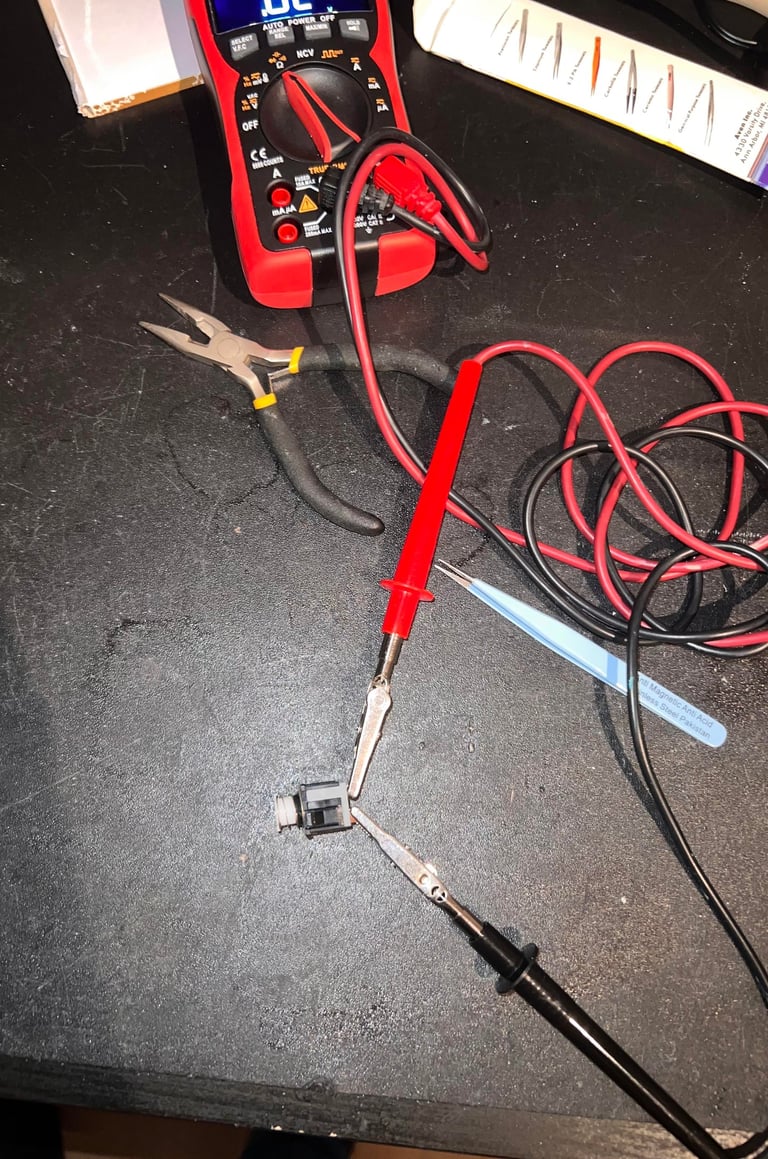
Repairing the SHIFT-LOCK key
It turns out that the SHIFT-LOCK key is not working properly. To repair this the key is disassembled and cleaned with isopropanol. After the repair the SHIFT-LOCK key is tested with a multimeter to verify that it works as it should.


The result of the keyboard refurbish is very promising. See pictures below.
Mainboard
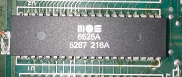
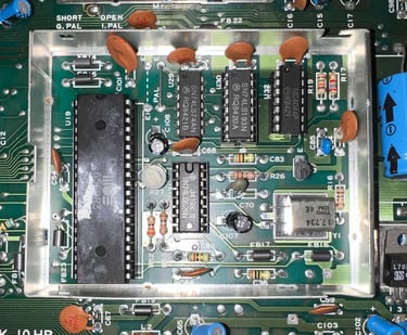
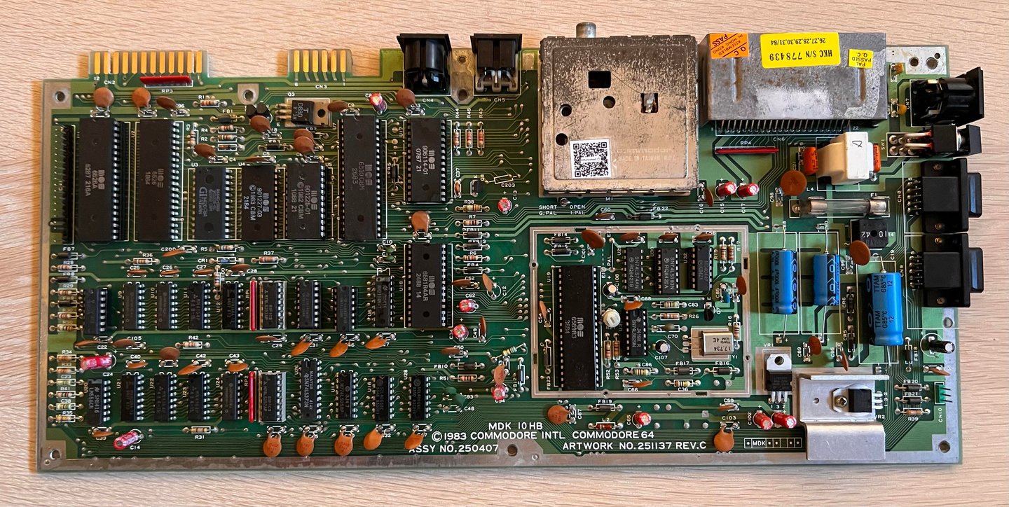
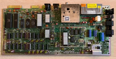
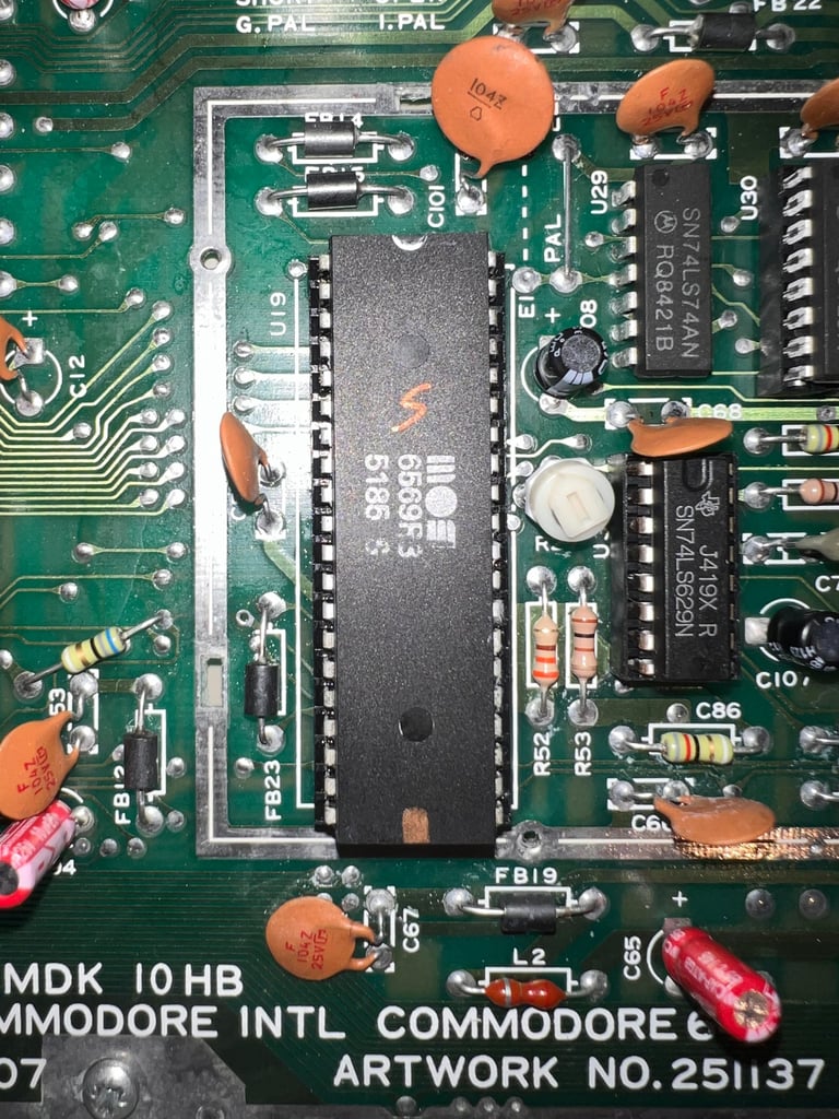
This mainboard is of type ASSY 250407 / Artwork 251137 (Rev C) - MDK 10HB. See picture below (note that the SID chip is removed in this picture).

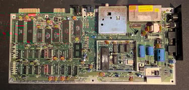
Visual inspection
The mainboard looks to be without any corrosion, and it is not very dirty. Some observations before refurbishment:
The power switch is not working as it should – at the moment it is stuck in “ON” position.
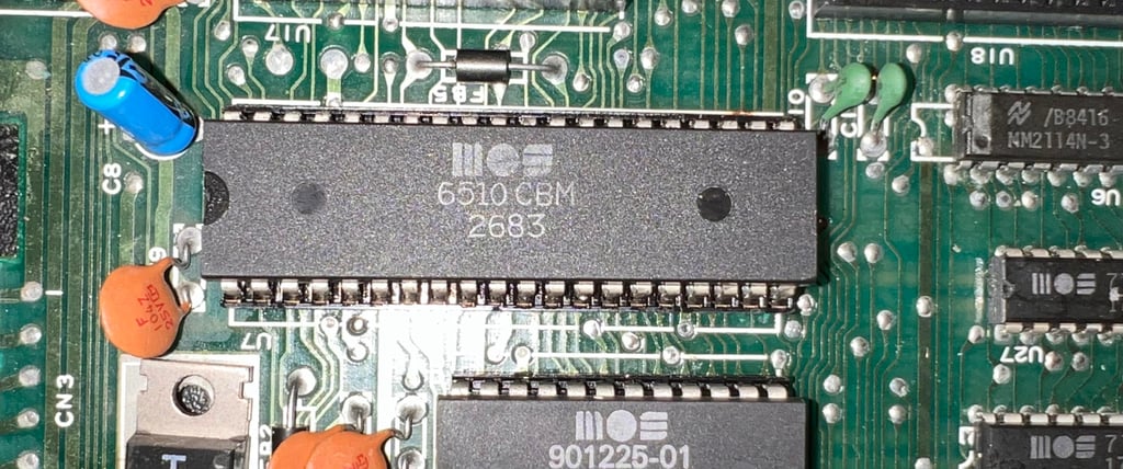
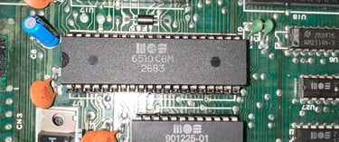
The MOS 6510 CPU is socketed and a bodge wire is protruding from the socket. I can also see a small uninsulated wire from one of the copper traces to the socket. It appears to me that this is from a previous repair.
The MOS 901225-01 Character ROM is socketed. My guess is that is from a fault finding process in a previously repair.
The MOS 906114-01 PLA is socketed. Same as above: my guess is that is from a fault finding process in a previously repair.
Both 74LS257 chips are socketed. Same as above: my guess is that is from a fault finding process in a previously repair.
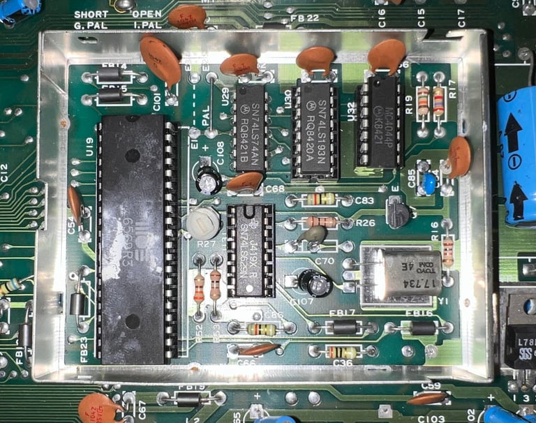
U30, U31 and U32 in the clock circuitry are socketed. Same as above: my guess is that is from a fault finding process in a previously repair.
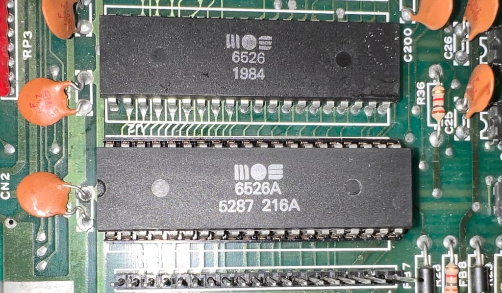
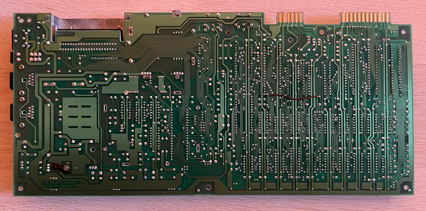
U1 MOS 6526 CIA #1 is not socketed but it is obvious that this chip has been desoldered during a fault-finding process. There are signs of solder on the IC legs and flux residue on the back of the PCB.
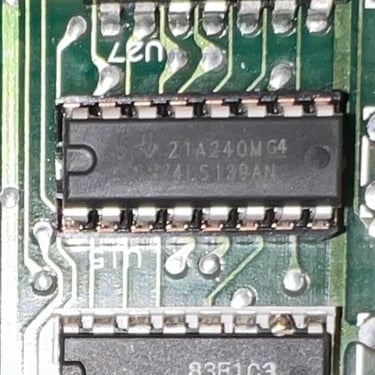
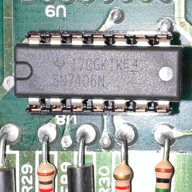
Three MOS glue logic chips; U27 (7712), U15 (7711) and U8 (7707). These are notorious for failing and should be replaced with modern 74xx series ICs.
The SID chip is a MOS 6581R4AR (!). This is known as “the best” version of the old SID chips. Fingers crossed that it works…
In the table below the main chips are listed (before refurbishment - some may be changed during repair if required).
Studying the table below you can assume that the machine was manufactured sometime in the middle of 1984. The reason for this is that several of the soldered chips (RAM, CIA #2, ROMs etc) are from this period. Other chips such as the CIA #1, PLA, Character ROM and SID are obviously from other periods up to 1988. This machine has probably lived a good life with a lot of use and joy!
Initial testing
Before the machine is powered on for the first time it is good practice to remove the SID chip and to check for a short circuit on the +5V DC and 9 V AC power rail. This is easy to check at the user port – see the article of Checking the C64 voltages for the position of these. Luckily, there are no short circuit so it should be safe to power on. And since the power switch is stuck in “ON” position it is just a matter of connecting the power supply (PSU).
Result of the power on is <DRUMROLL> BLACK SCREEN </DRUMROLL>. Ah, the classic, black screen… so this is going to be both a repair and refurbish.
Checking the voltages
For the Commodore 64 to operate flawlessly the voltages needs to be within range. To see what voltages are relevant, and where they can be measured, can be found in the article Checking the C64 voltages.
In the table below the measured voltages are listed. Note that this table will be updated after repair/refurbish also.
All voltages are within acceptable range. The +5 V DC for the VIC-II is a bit low, but nothing alarming. It could be that this voltage will be improved when a new modern 7805 voltage is installed.
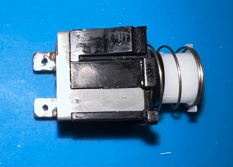
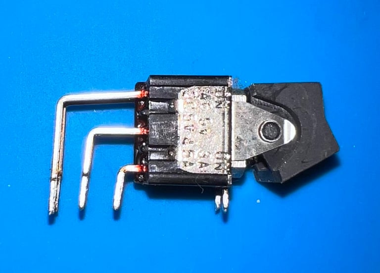
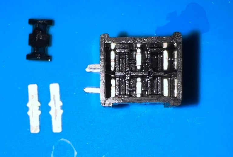
Repairing the power switch (SW1)
It is not uncommon that the power switch on these machines fails. I must admit that I have not encountered a switch is really stuck in the “ON” position, but I think this can be fixed.
The power switch is desoldered from the mainboard. This is a quite straightforward task, but it is important to make sure that all the eight pins are completely desoldered before you start wiggling it off the PCB to prevent damage.
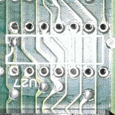
Below is a picture of the mainboard after desoldering. No traces or pads were lifted.

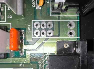
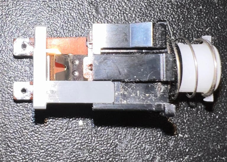
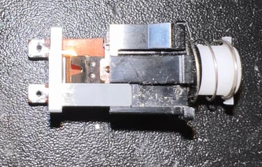
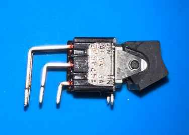
The switch is disassembled by carefully using a small thin flat screwdriver to pry it open. All the small parts are cleaned with a Q-tip and isopropanol. After cleaning the switch is assembled and soldered back into the board. The switch is now able to turn ON/OFF without any issues. There is still a black screen, but that is expected.

Refurbishing the CIA #1 area
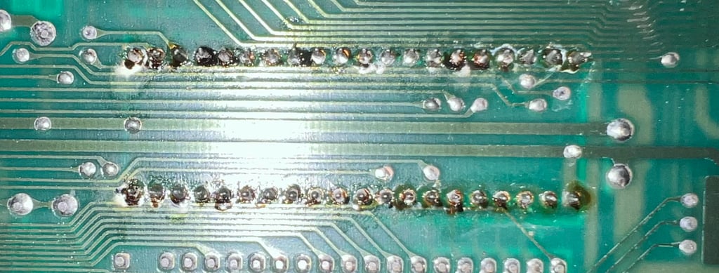
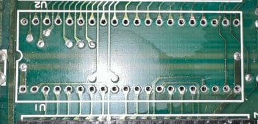
I do not claim to be an expert on soldering, but the work done on MOS 6526 CIA#1 (U1) is not good. It might work ok, but it looks terrible. There is massive flux residue on the backside, several of the points seems to be only half way soldered and there are even solder on the top of the IC legs.
The CIA#1 has obviously been removed during a previous repair. Its not that I expect the CIA#1 to be the culprit of the black screen, but I will remove and refurbish this area anyhow. I just can´t have it like this.
Also, there is some additional value removing the CIA#1. The Commodore 64 is not relying on this IC in order to boot from the Dead Test Cartridge. So by removing this IC I also can rule out that the CIA#1 is the cause of the black screen.
Below is a picture of the CIA#1 area before refurbish.


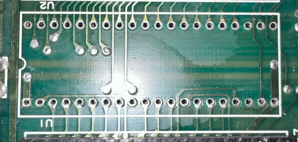
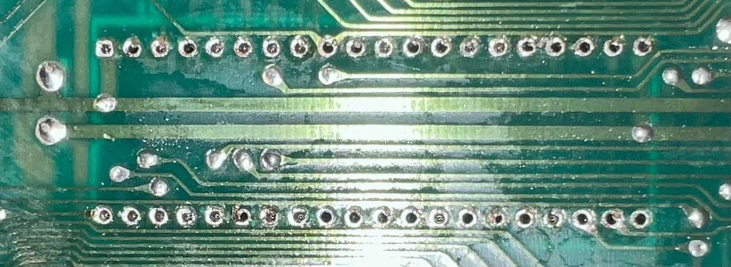
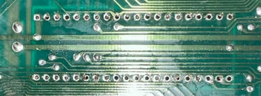
The CIA#1 is carefully desoldered using a desoldering gun and hot air. Luckily it seems that no pads are damaged. Also, I check traces for continuity with a multimeter and I can not find any damaged traces. The desoldered area doesn´t look perfect, but I think its way better than before. See pictures below.
A new socket is installed in U1, and the CIA chip is inserted. To no surprise there are no change: still a black screen. In the picture below the CIA chip is installed in the new socket.

Refurbishing the CPU area
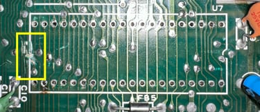
As mentioned the CPU (U7) is socketed after a previous repair. Also, there is a bodge wire from protruding from the underside of the socket and an uninsulated wire is also visible. It also turns out the uninsulated wire is loose (?).
To make sure that there are no damaged traces or pads I choose to desolder the socket. The old bodge wire and uninsulated wire are removed. Below is a picture of the area after desoldering and some initial cleaning. Note that there is an area where someone has actually cut a trace intentionally and then replaced with the bodge wire. Even if the area looks a bit messy it turns out that the rest of the traces are working fine (they are checked for continuity).

A new 40 pin socket is installed and soldered in place.
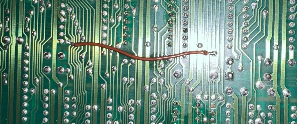
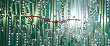
I think its better to have the bodge wire on the backside of the PCB. It is easier to do maintenance this way instead of the wire stuck under the socket. Below is a picture of the bodge wire connected on the backside.
The CPU is put back into the socket and the machine is tested again with the Dead Test Cartridge. And now something happens! There is no black screen any more while running the Dead Test, now some graphical garbage is shown. So something was probably wrong with the socket as this is somewhat an improvement. See pictures below.
Checking the VIC-II and refurbishing the VIC-II area
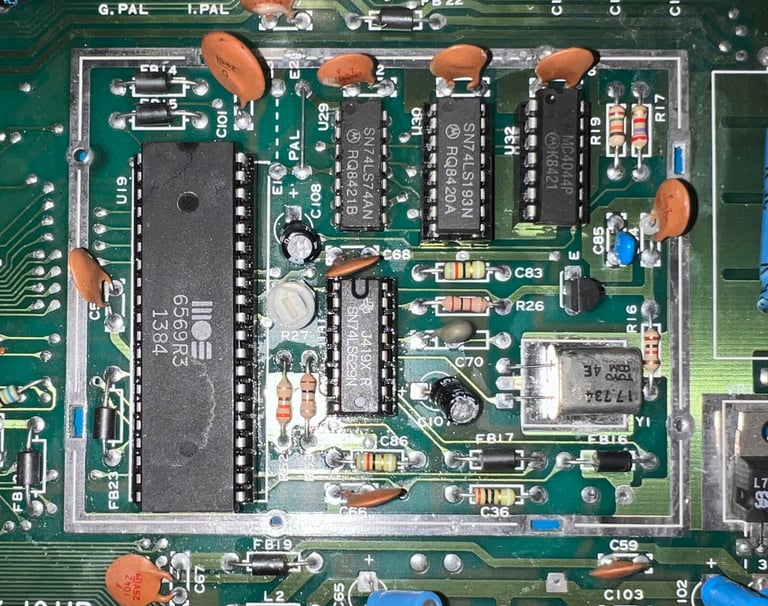
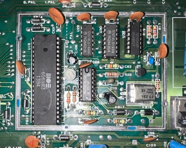
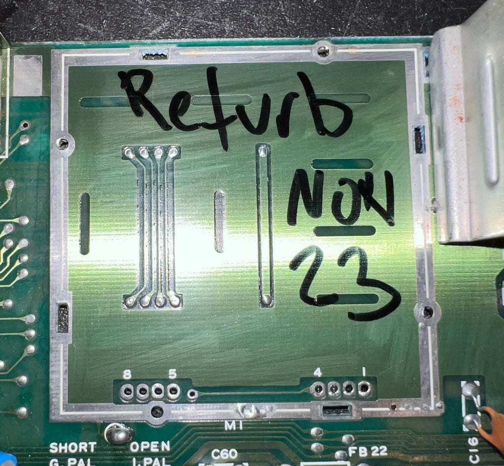
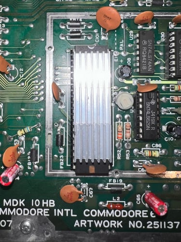
Since there is some sign of life now I choose to check if the VIC-II is actually working. This is easy to do by replacing the chip with a known working VIC-II and see if anything changes. But before I do that I remove the RF-shield bracket surround the VIC-II area. The RF-shield is obsolete in modern times – it only encapsulates the heat which can deteriorate the VIC-II. Also, it is much easier to remove the VIC-II chip after the shield is removed. When it is removed you can use a chip lifter on both side of the chip to reduce the risk of damaging it.
It is trivial to desolder the RF-shield, and no real damage can be done. For the ease of removing the shield some hot air is used in combination with the desoldering gun. Below are pictures of the VIC-II area before and after the shield bracket is removed.
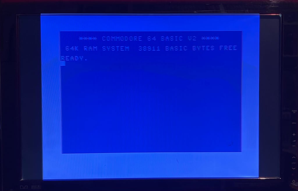
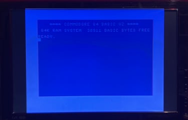
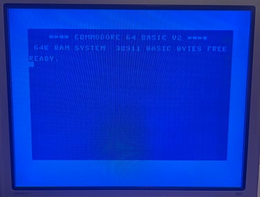
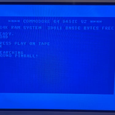
A known working VIC-II is borrowed from Commodore 64 breadbin ser. no. 828599. And… the well known Commodore 64 BLUE SCREEN appears! 38911 BASIC BYTES FREE! So the VIC-II was bad (these are very expensive so this is going to be a costly repair). There could of course be other faults, but so far we had a bad CPU socket and a bad VIC-II.
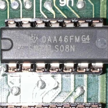
Replacing the MOS glue logic
Some Commodore 64 mainboard has “glue logic” made up of MOS ICs. Unfortunately, these are notorious for failing. But luckily there are modern replacements and therefore it is good practice to replace these old MOS glue logic chips – even if they work at the moment. They will fail eventually.
Below is a table of the MOS chips and their modern replacements which will be installed.
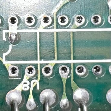
All MOS glue logic chips are desoldered without any any damage to traces or pads. Sockets are installed and new modern chips are installed. Below are some pictures from the process.
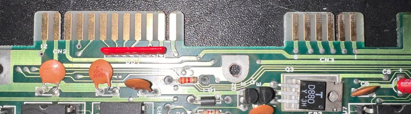
Replacing the electrolytic capacitors – RF modulator
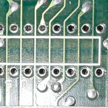
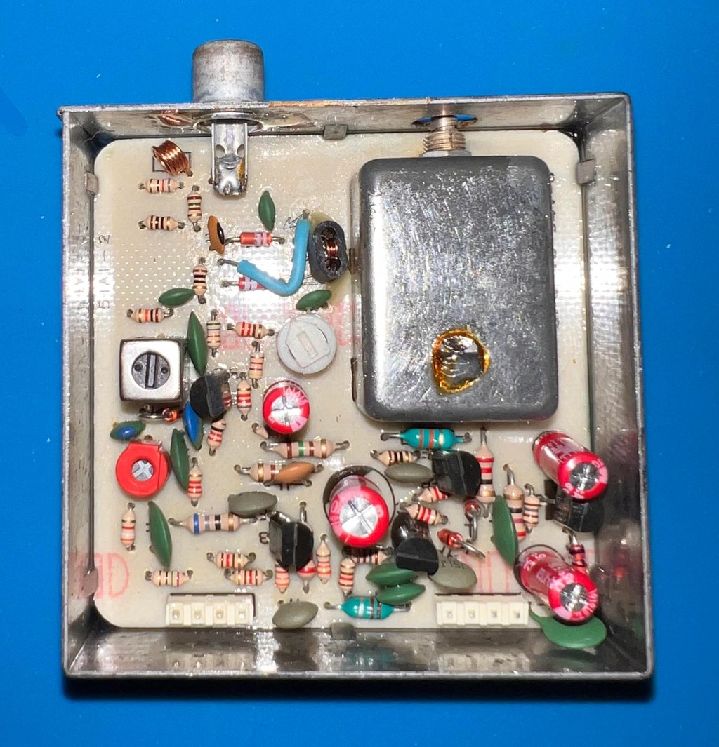
It is good practice to replace the electrolytic capacitors in the RF modulator. But it is not trivial to desolder the RF modulator from the mainboard without damaging traces or pads. In the HOWTO article “Desolder the RF-modulator” I explain how I do this using a combination of soldering iron, desoldering gun and hot air.
Below is a picture of the mainboard after desoldering the RF-modulator. No traces or pads were damaged during the operation.

This is a Commodore P/N 251025-01 RF-modulator which contains the following electrolytic capacitors:
1 x 10 uF [16 V]
2 x 100 uF [10 V]
1 x 470 uF [7.5 V]
Note that the 470 uF is replaced with a capacitor with slightly higher voltage rate: 10 V. As long as the voltage rating is higher this is perfectly fine. Below is a picture with the new electrolytic capacitors in place.

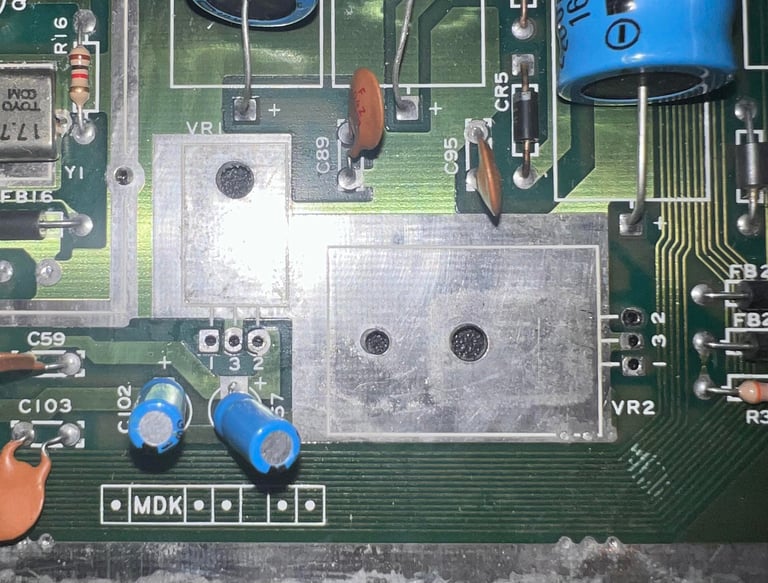
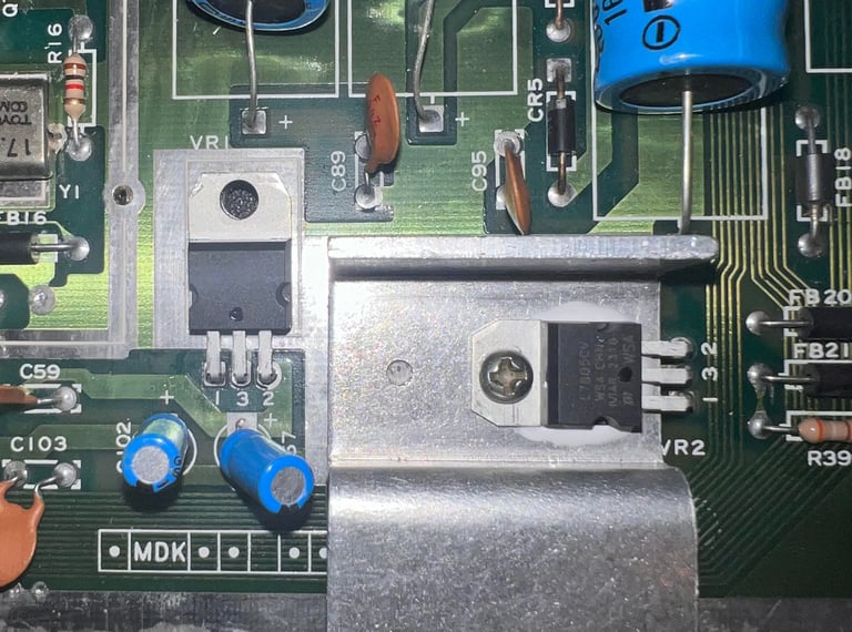
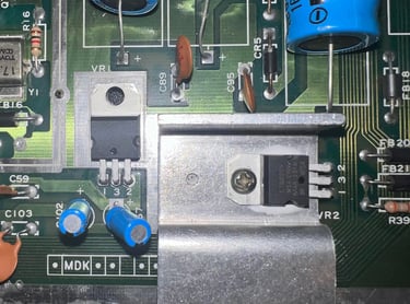
Replacing the voltage regulators
In the breadbin version of the Commodore 64 there are two voltage regulators on the mainboard. The full story of the purpose of these two can be found in the HOWTO article “Checking the C64 voltages” – but in short these are used to supply the VIC-II circuitry and SID with +5V and +12 V DC.
Since it is crucial that these voltages are both within acceptable tolerances and that the regulators don´t give too high output it is good practice to replace these. The Commodore 64 is pushing 40 years so these old voltage regulators are old – and can fail.
Below are some pictures from the desoldering and replacement of new 7805 and 7812 voltage regulators. Note that the 7805 voltage regulator is placed on a heatsink (with some heat paste) and the 7812 is free floating.

Replacing the electrolytic capacitors – mainboard
The electrolytic capacitors are old. Almost 40 years. Old electrolytic capacitors tend to change their capacitanze or ESR value due to old age. Normally, this is not a big problem for the Commodore 64 to function, but it is good practice to replace these as part of refurbishment to make sure that old capacitors don´t make the Commodore 64 behave odd. A complete list of all the replaced capacitors can be found in the Capacitor List library.
Below are some pictures after the new electrolytic capacitors are installed.
Cleaning the user- and datasette port
For the Commodore 64 peripherals (modem, datasette) the interfacing ports needs to be clean and undamaged. After years, the copper is often dirty and oxidized. Therefore these needs to be cleaned properly. To do that a rubber eraser is used to carefully clean and revive the connectors. Finally the connectors are cleaned with isopropanol and a Q-tip.
Adding heat sinks to custom (MOS) chips
As a means of extending the life of the most valuable custom MOS chips heat sinks are added. Even though most of the heat is transferred from the IC pins to the mainboard some heat is also radiated to the surrounding air. To make this transfer IC to surrounding as efficient as possible heat sinks are installed on the MOS 6510 CPU, MOS 6581 SID, MOS 6569 VIC-II and MOS 906114-01 PLA.
Below is a picture of the mainboard with the heat sinks added.

Testing
Proof is in the pudding - does it work?
Testing is done through two main stages:
Testing the basic functionality and chips
Testing by using the machine playing demos, games etc. accessed by both floppy and datasette to verify correct operation
Basic functionality and chips
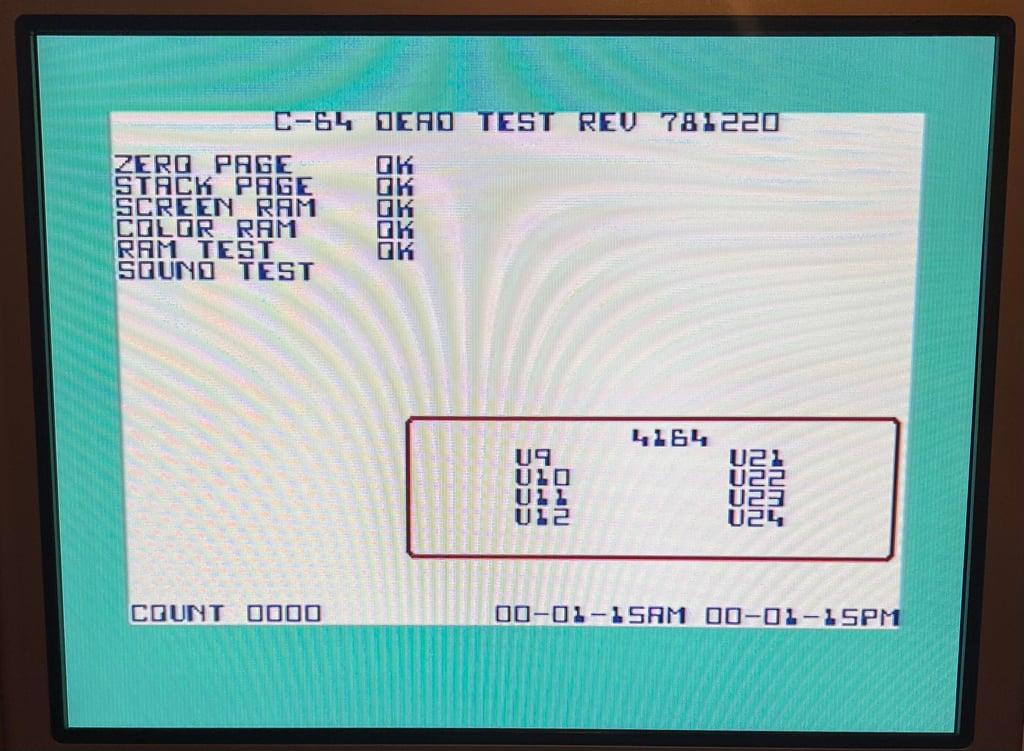
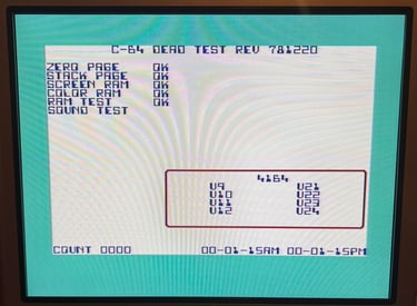
First test is done using the Dead Test Cartridge. This test doesn´t test all the functionality of the Commodore 64, but it does test the basic functionality of the major chips such as the CIA #1/2, CPU, VIC-II, PLA, RAM and SID. As the picture shows below the test is passed.
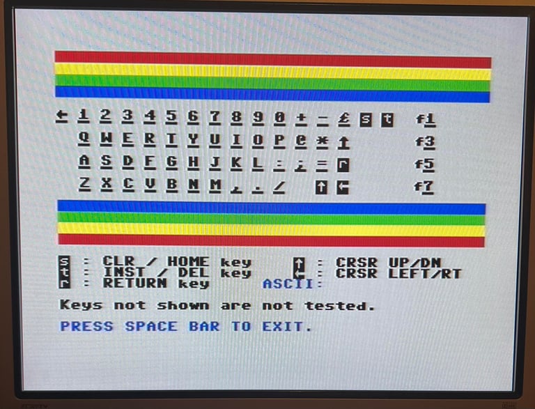
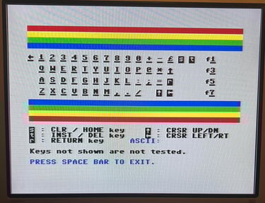
Next test is to power the Commodore 64 to the blue boot up screen and also check the keyboard to make sure all keys works as they should. The test is passed; all keys works and 38911 BASIC Bytes Free.

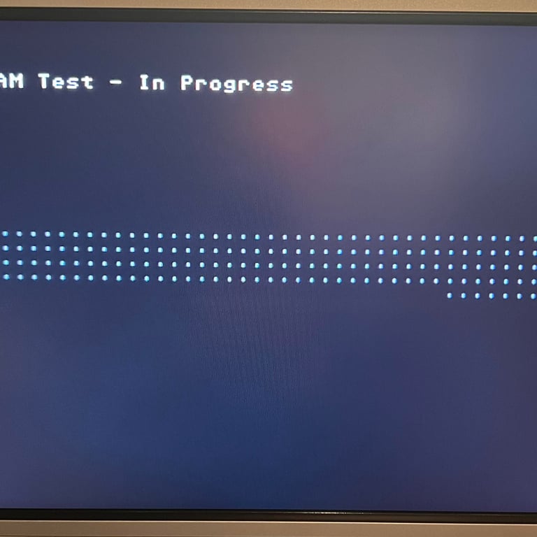
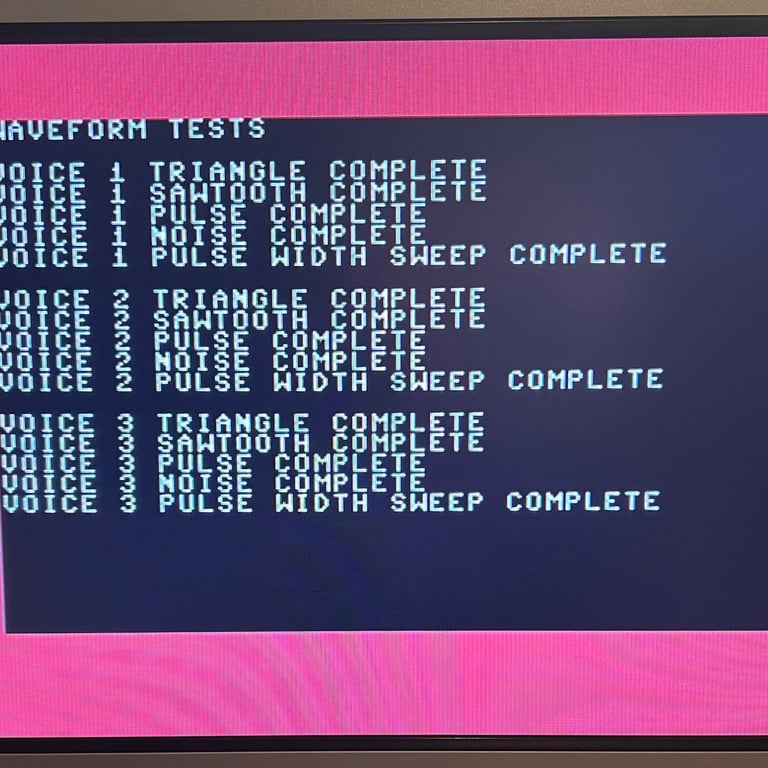
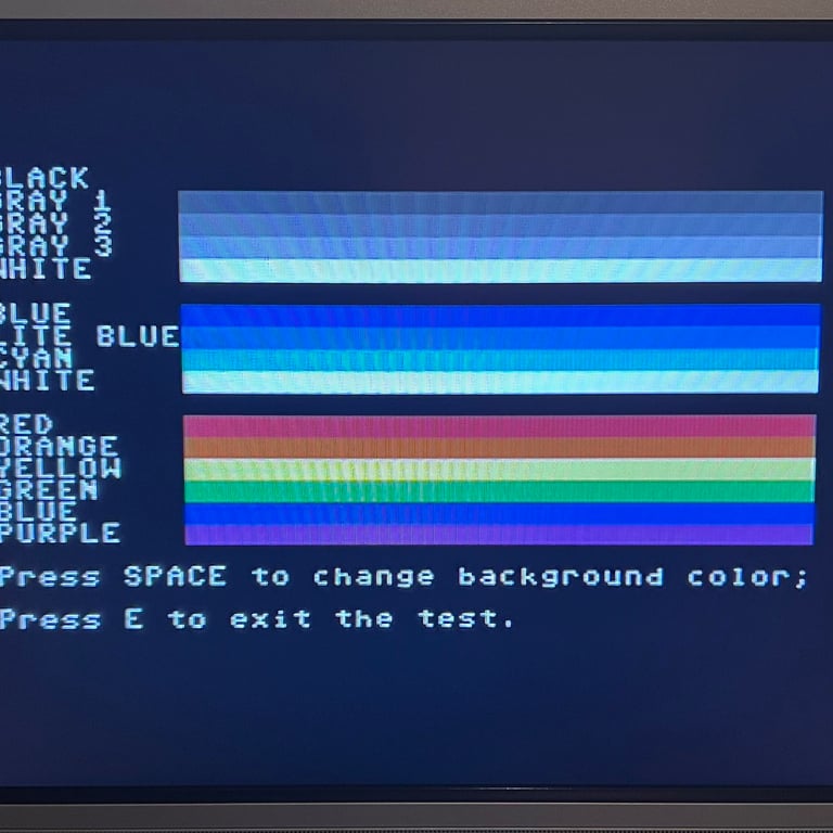
The basic functions of the VIC-II, SID and RAM is tested with 64 Doctor. Note that this is to be considered as basic functionality - more advanced (?) functionality such as sprite handling / collision detection / advanced audio will be tested later. But the basic tests pass without any detected faults (click to enlarge).
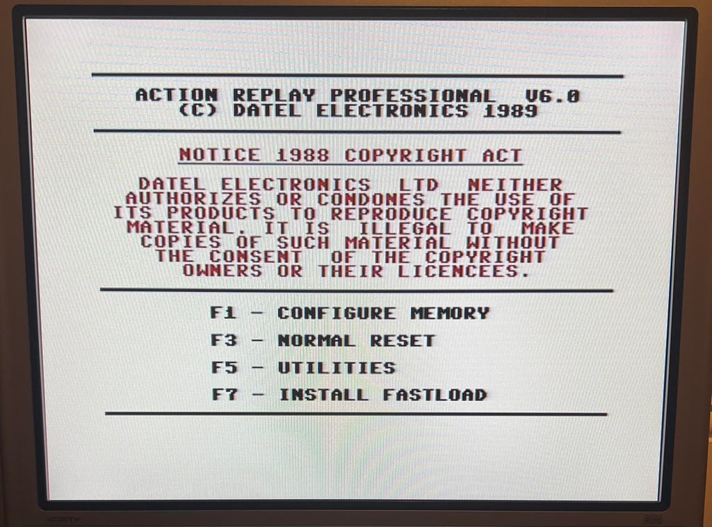
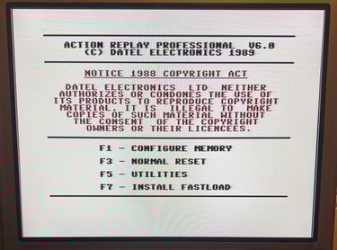
Last basic check before moving to more extensive testing is checking the cartridge. This is done by using the Action Replay VI. Result is that the test is passed.
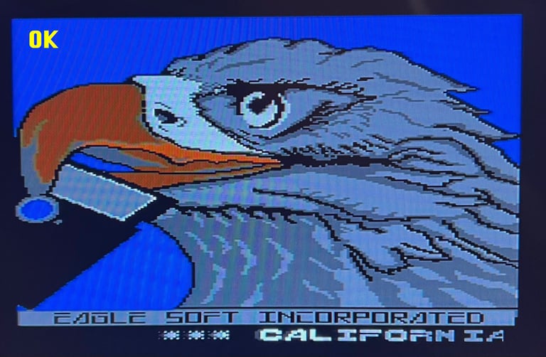
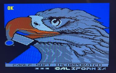
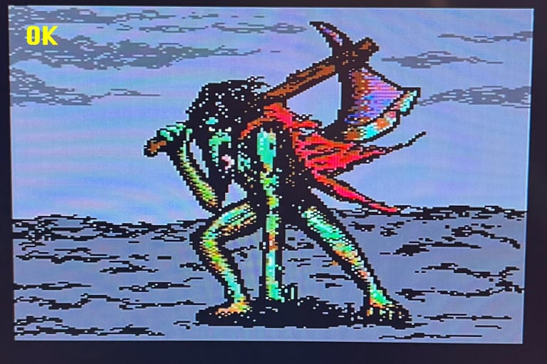
Extended testing
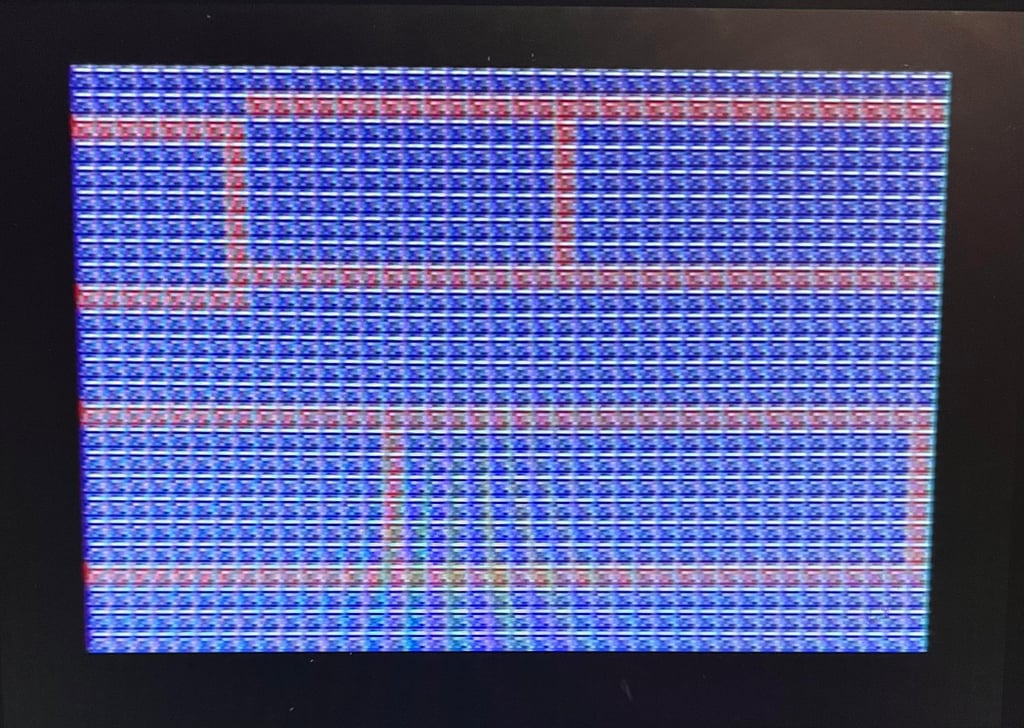
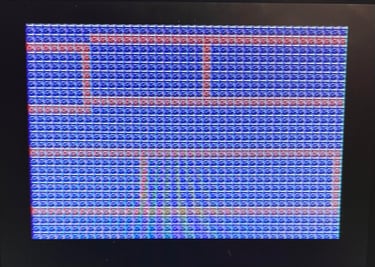
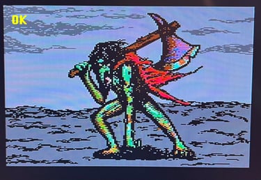
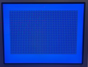
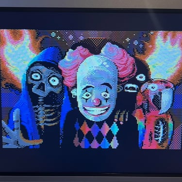
Knowing that the basic functionality of the machine works I continue the testing by using the Commodore 64 for normal operations; playing some games, watching demos, loading from datasette and floppy and using a cartridge. And this is the real value of the extended testing... I now detect a serious fault. When the machine operates in bitmap multicolor mode some 8 x 8 pixel areas are not displayed correctly. See pictures below.


Repair
Checking the color RAM
The fault is probably caused by a marginal VIC-II chip or bad color RAM. I do not really think it´s bad color RAM since the fault is only visible in bitmap mode. Nevertheless, I write some short assembly programs checking the color RAM in normal character mode (the color RAM has not knowledge if the stored data are used in bitmap mode og character mode). Below is a picture of the short program and the result -> all colors are stored in color RAM.
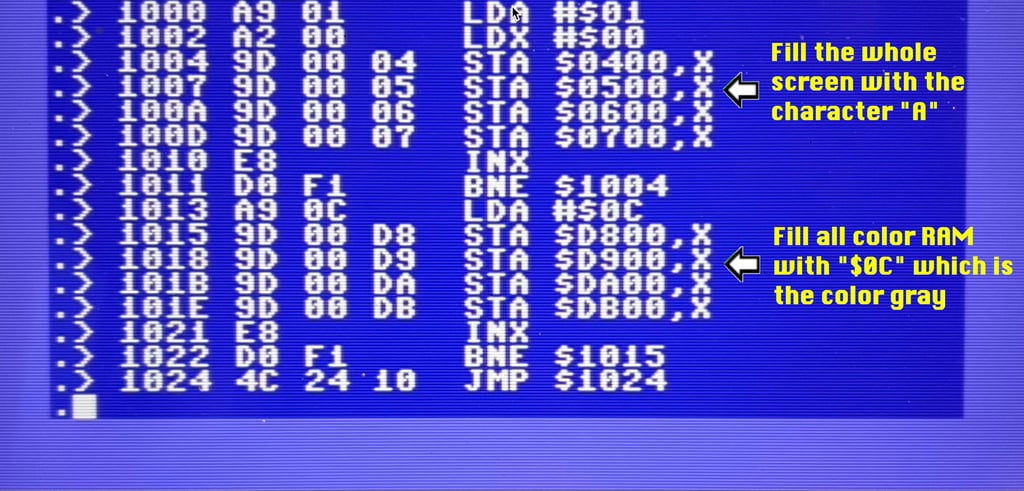
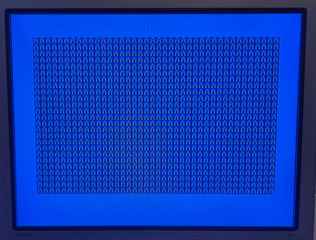
With SYS 4096 the short program is executed with the result shown below. As can be seen all "A" as coloured grey -> indicating the color RAM is ok.
Checking the VIC-II
Another candidate for the fault is the VIC-II. Even if the VIC-II seems to work ok most of the time, it can be marginal - meaning that some functions is not completely working. Luckily, the VIC-II is easy to remove and replace since it is already in socket. And result... SUCCESS! With a "new" VIC-II chip the graphics now looks as it should. Nevertheless, it´s sad that the VIC-II was broken since replacements have become very expensive.
A VIC-II is ordered from retroleum.co.uk and installed in the machine. I can highly recommend retroleum - always fast and excellent service!


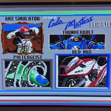
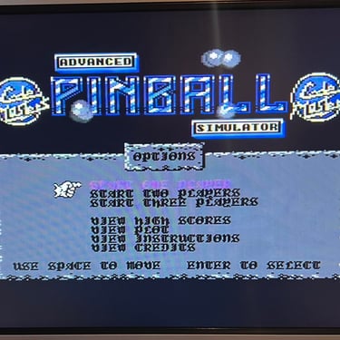
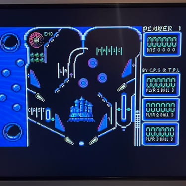
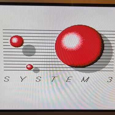
Testing - cont.
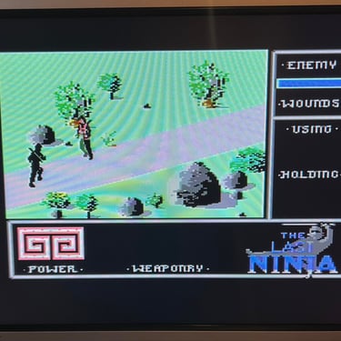
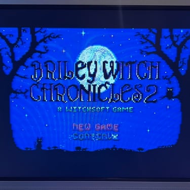
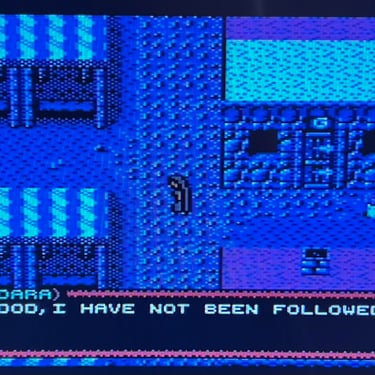
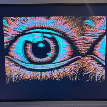
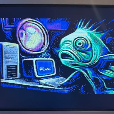
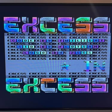
The extended testing is continued with the new VIC-II chip. Testing the Commodore 64 in various ways; playing games, watching demos, loading from datasette and floppy and using a cartridges. I can not find any issues with this machine. I also pay special attention to the video to make sure that there are no glitches in the graphics - I can´t see any abnormalities. Below is a gallery with pictures from the testing.
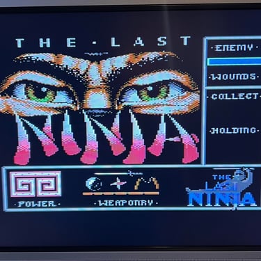
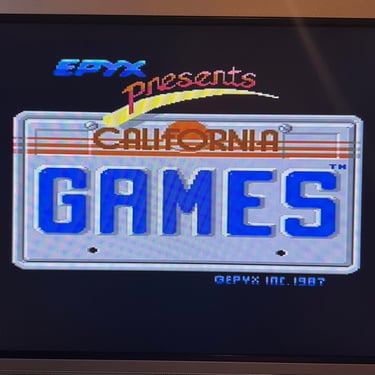


Final result
"A picture worth a thousand words"
Below is a collection of the final result from the refurbishment of this C64 breadbin. Hope you like it! Click to enlarge!


Banner picture credits: Evan-Amos