

Competition Pro
Starting point
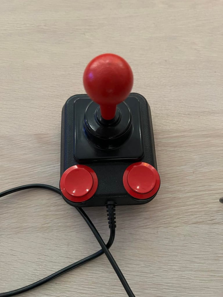
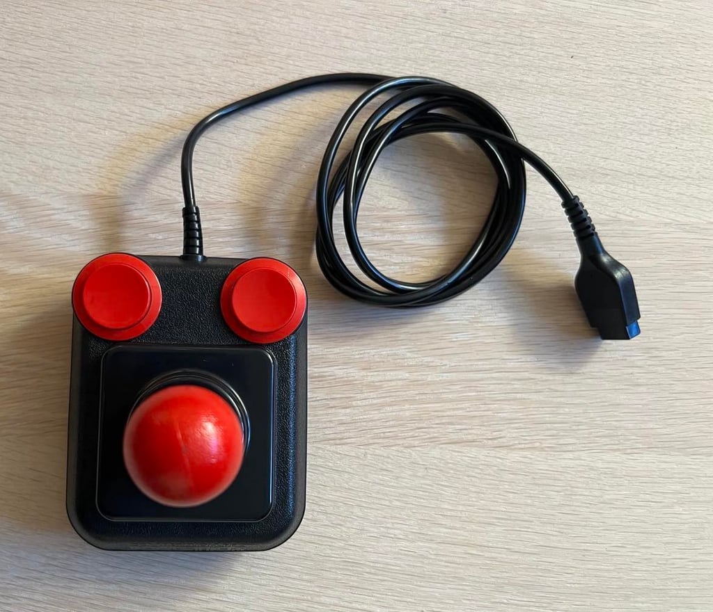
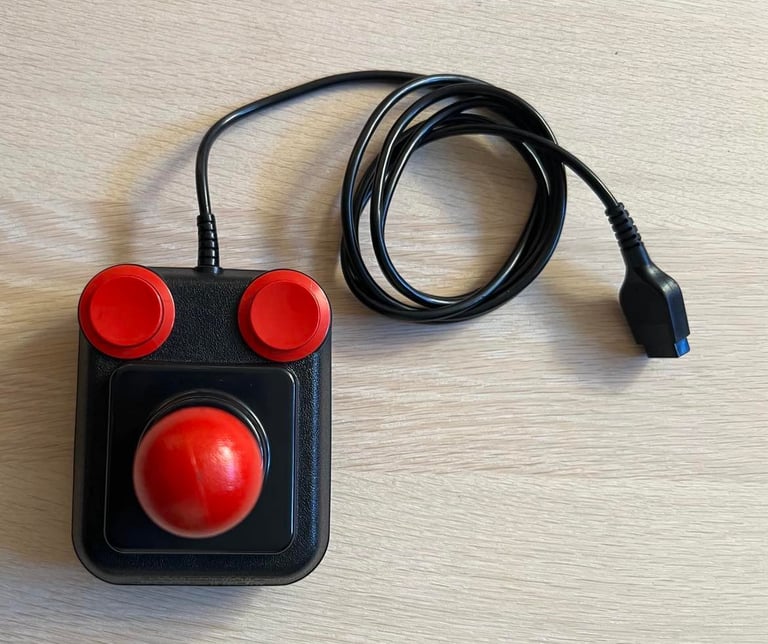
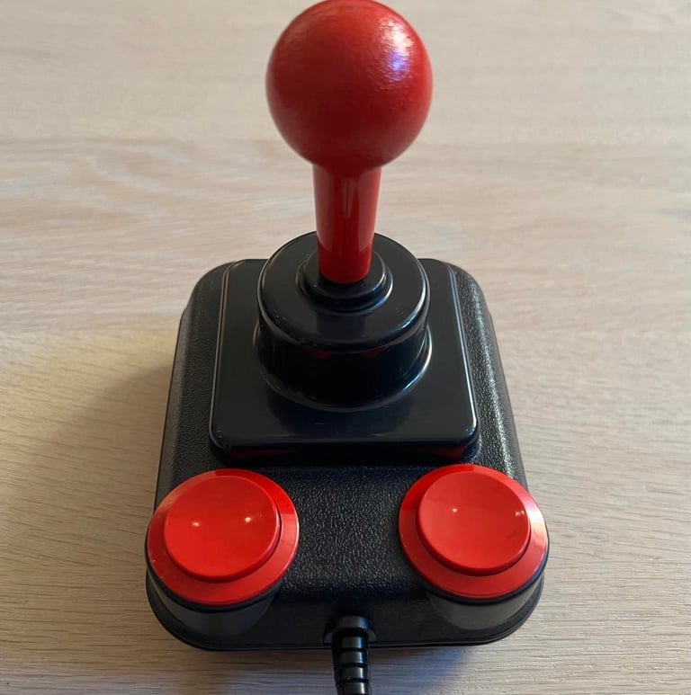
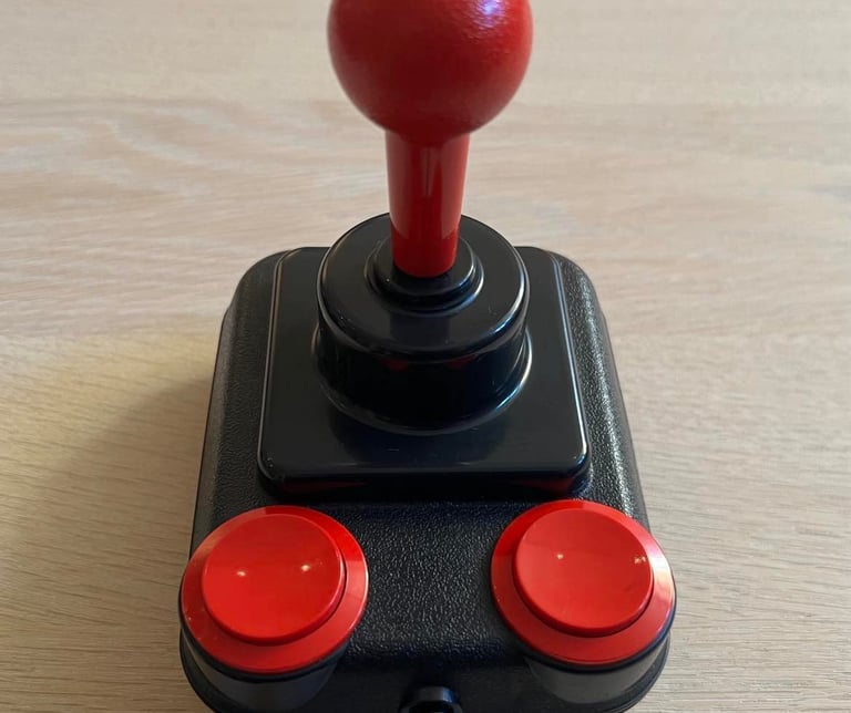
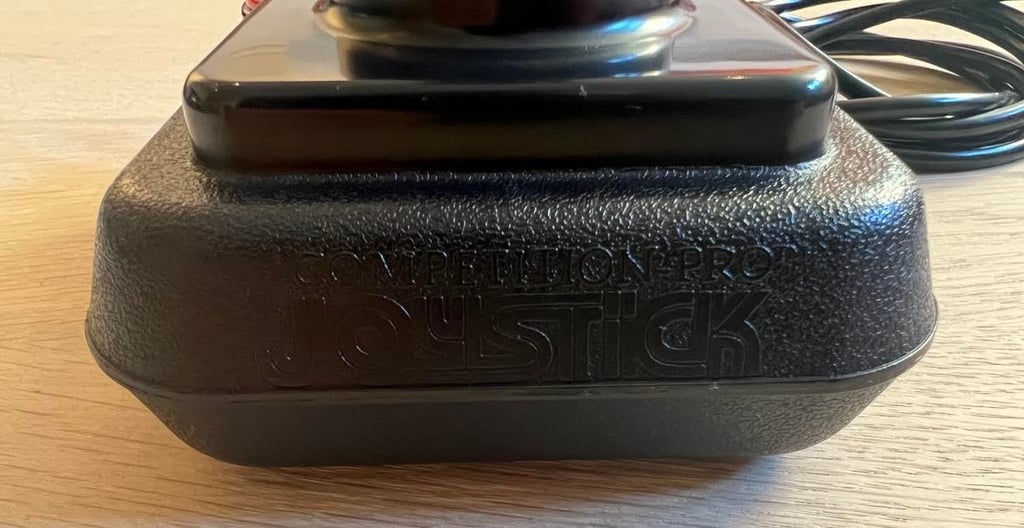
Competition Pro is a high quality joystick and seems to have stood the test of time. From the outside it looks undamaged. Somewhat dirty, and makes a "squeaky" sound when moving the shaft. But I think that this joystick will both work and look good after refurbishment!

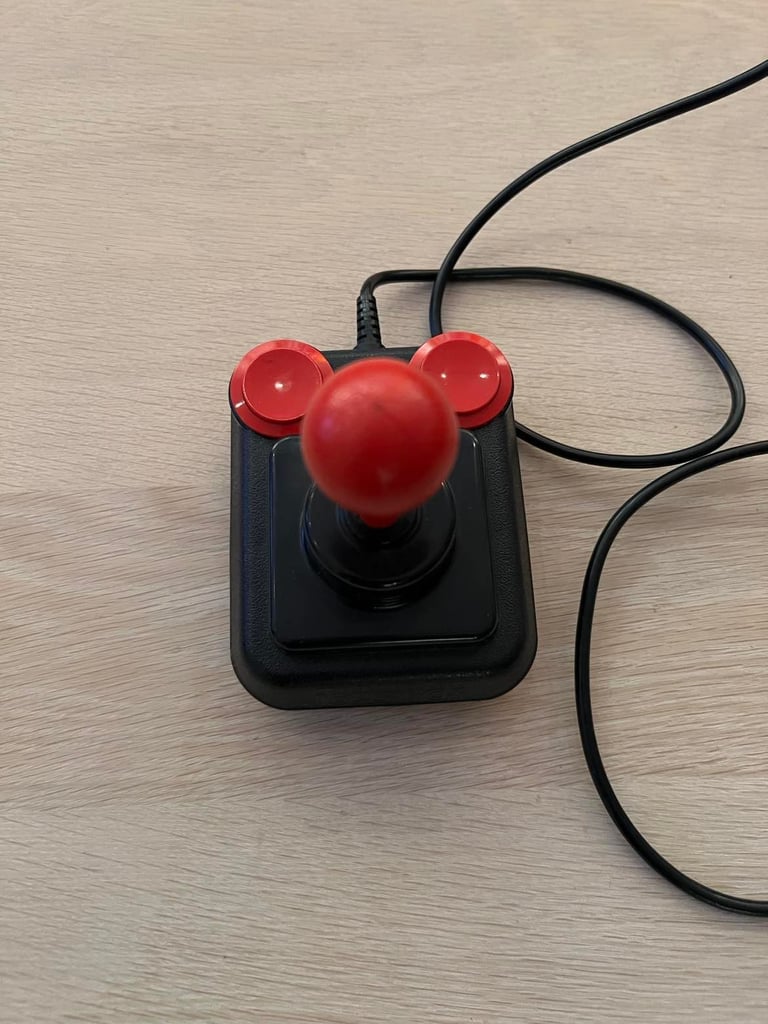
Funny thing is that this joystick also have the same "bald" effect: there is a small dark spot at the top of the ball. I´ve seen this before with Competition Pro joysticks.
Refurbishment plan
To refurbish this Competition Pro joystick the plan is to do this by:
Cleaning the exterior casing
Check (and potentially repair) the interior electronics, switches and mechanics
Check cable connectivity
Verify operation by testing
Exterior casing
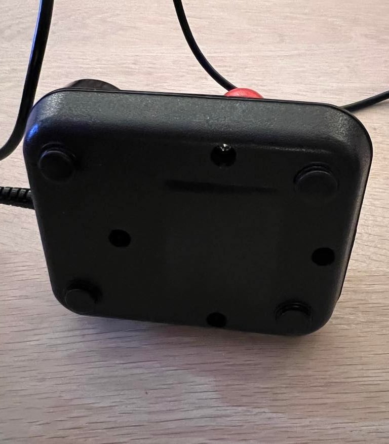
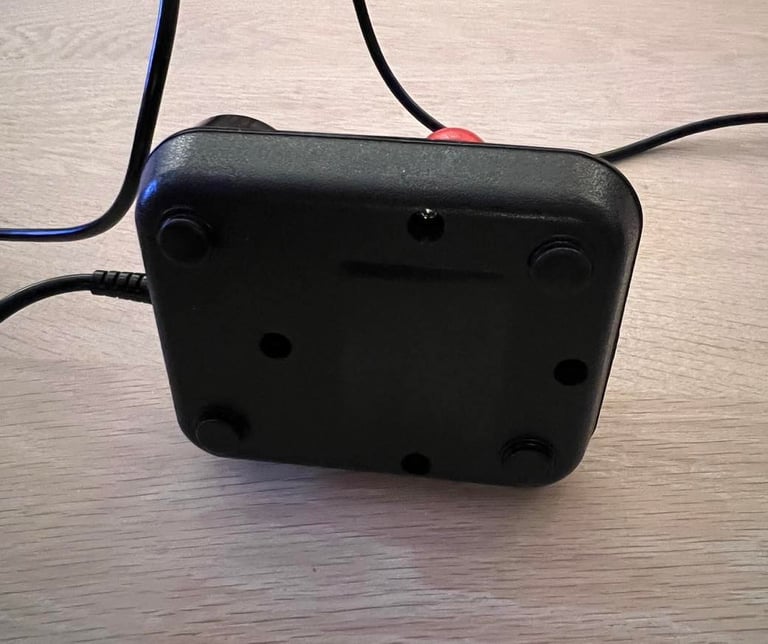
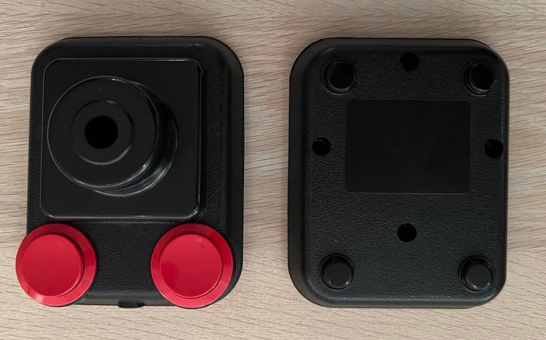
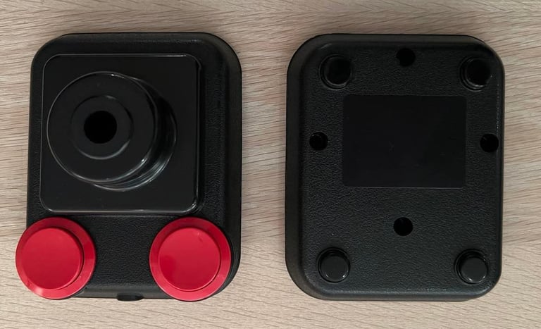
The joystick casing consists of a top- and bottom cover which are fixed by four screws at the bottom.
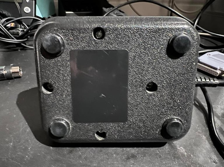
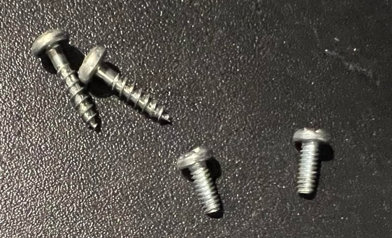
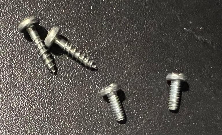
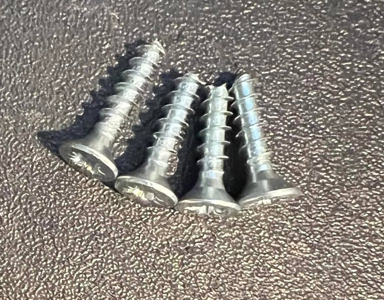
When removing the screws I notice that someone has probably been here before; there are two kind of screws? Is this from production? I´m not sure, but I doubt it. There are two wood/plate screws and two machine screws.
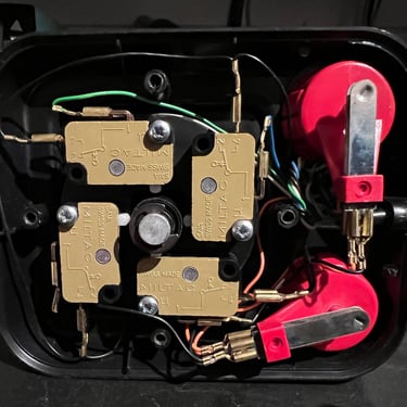
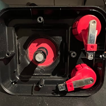
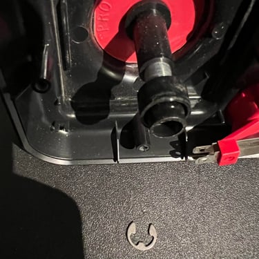
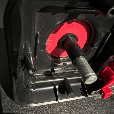
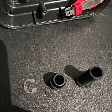
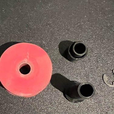
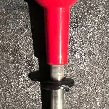
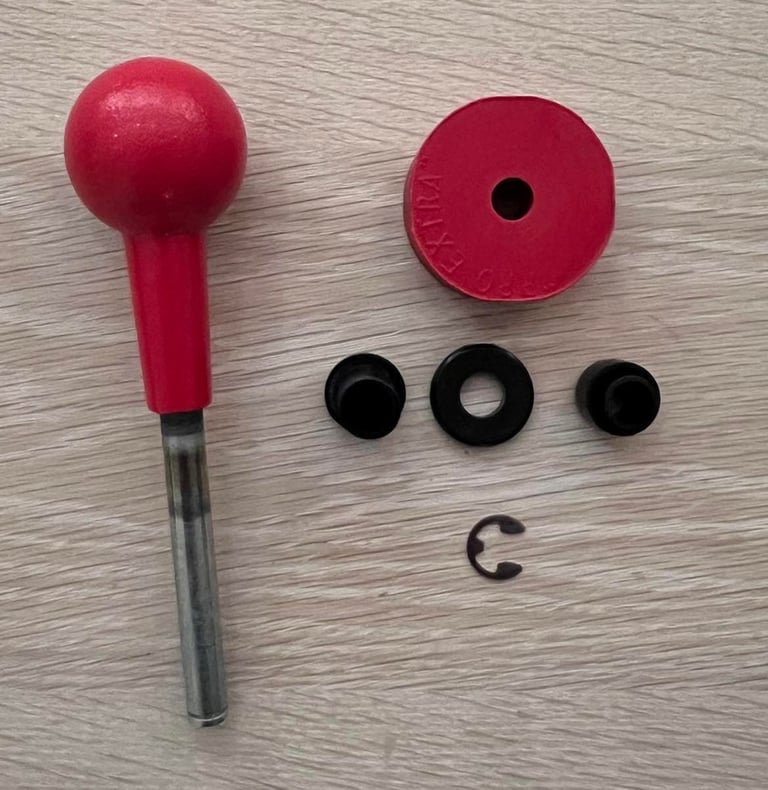
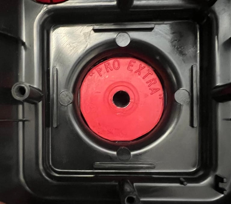
To get a good clean the shaft has to be disassembled from the casing. This is done by first removing the plastic bracket holding the four microswitches and disconnecting the fire button connectors. Then the metal clip from the bottom of the shaft is removed with a small screw driver. Further on the two plastic "tubes" are removed from the shaft. And at last the large rubber ring is removed by pushing it from the top side. Below are some pictures from this process.
The all plastic parts are carefully cleaned with mild soap water. And all parts, except the rubber ring, is cleaned with glass cleaning spray.

Now I notice that in addition to the top of the shaft ball there is also a small dark spot on the left fire button. Not a big deal, but it´s there.
I use some MoS2 grease with a Q-tip to lubricate the rubber ring - but just on the inside and edges of the ring so that no grease will get to the microswitches.
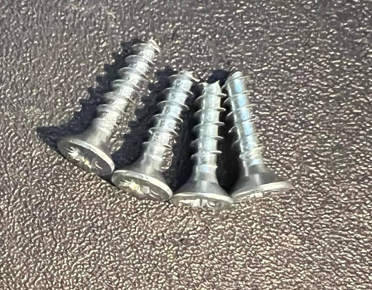
To replace the screws I choose to make four new ones. I go for the cone shaped wood screws, but cut them a bit shorter than the original (?) ones. The reason for cutting them a bit short is that the plastic is brittle due to old age, and it is not really necessary to have such long screws I think.
Interior
There are no PCB in this joystick - only four microswitches attached to a plastic bracket. The two fire buttons are made from two leaf switches. As a matter of fact, there are also Competition Pro joystick which use microswitches for these buttons (and also a spring instead of a rubber ring).
All microswitches are cleaned with isopropanol, and sprayed with contact cleaner. I can´t see or detect any damage on these switches.
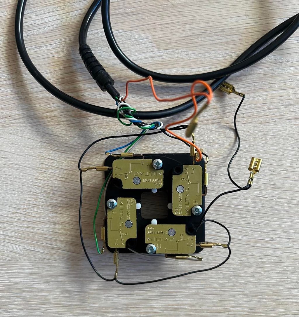

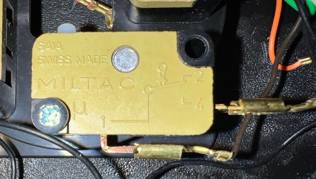
The microswitches are all of the brand "MILTAC" - Swiss made!

Connectivity
To make sure the joystick operates as it should all wires are controlled for connectivity. This is done by using the multimeter in "connectivity mode" (beep) and controlling each wire from the connector to the switches inside the joystick. Also while the multimeter is "beeping" the wire is wriggled to see that it doesn´t loose connection during e.g. gameplay.
This joystick only use six wires: UP/DOWN/RIGHT/LEFT/FIRE/GND. In the schematics below the pin configuration used while testing is shown. Note that the pinout shown below is seen from the C64 side. So when checking directly on the joystick the pinout is mirrored. Note that JOYx0=UP, JOYx1=DOWN, JOYx2=LEFT and JOYx2=RIGHT.

To make sure the joystick operates as it should all wires are controlled for connectivity. This is done by using the multimeter in "connectivity mode" (beep) and controlling each wire from the connector to the switches inside the joystick. Also while the multimeter is "beeping" the wire is wriggled to see that it doesn´t loose connection during e.g. gameplay.
This joystick only use six wires: UP/DOWN/RIGHT/LEFT/FIRE/GND. In the schematics below the pin configuration used while testing is shown. Note that the pinout shown below is seen from the C64 side. So when checking directly on the joystick the pinout is mirrored. Below is a picture from the testing.
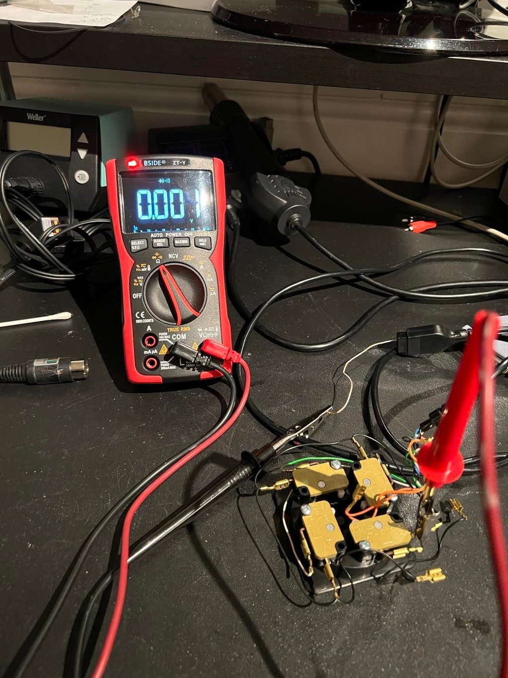
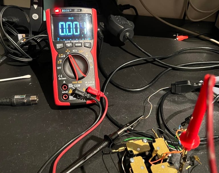
Result from testing is that all wires are ok, and that connectivity is fine. I can´t find any issues with the either the switches or the wires/connector.
Testing
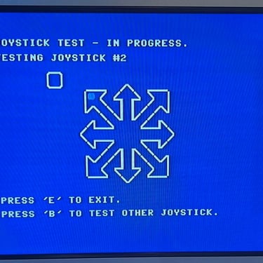
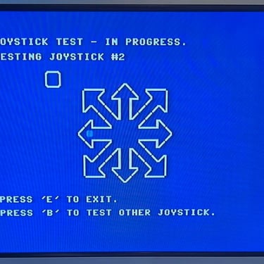
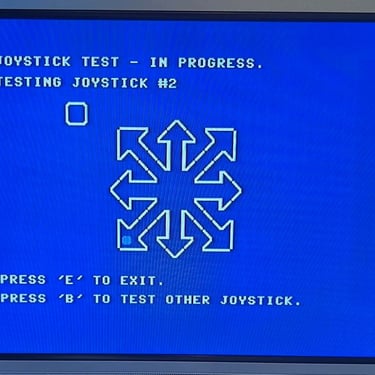
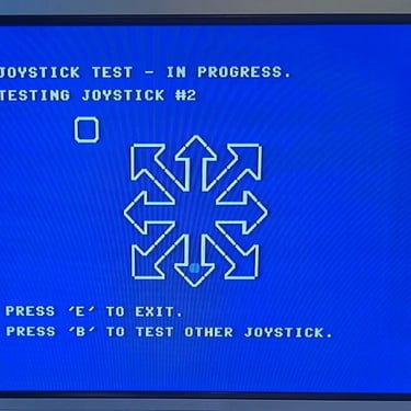
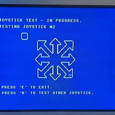
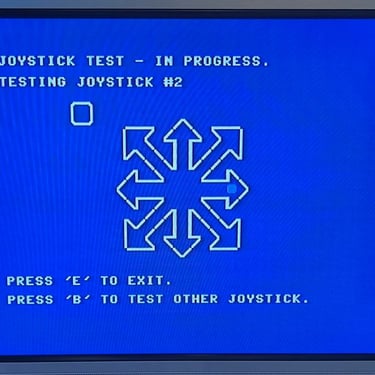
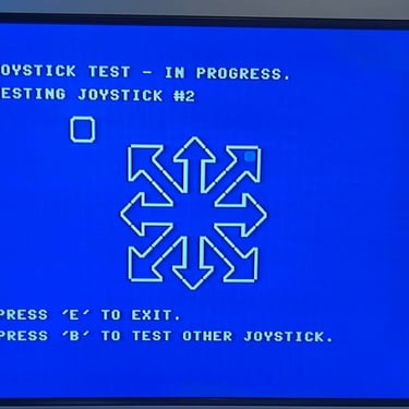
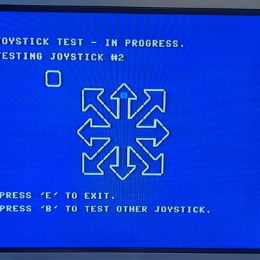
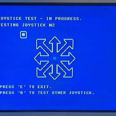
Testing is done by connecting the joystick to a known working Commodore 64. And using the 64 Doctor software to verify all directions and fire buttons. Also, verifying the direction also means checking combined directions such as UP+LEFT.
Pictures below shows the result from testing; all directions and fire buttons works fine. And the squeaky noise is also gone.
Final result
"A picture worth a thousand words"
Below is a collection of the final result from the refurbishment of this Competition Pro joystick. Hope you like it! Click to enlarge!

Banner picture credits: Kshade