

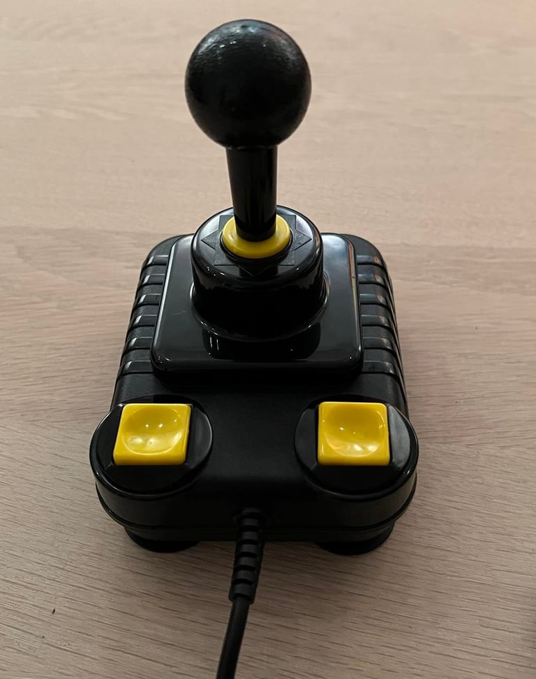
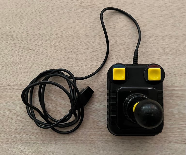
ZipStik
Starting point
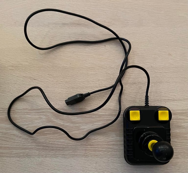
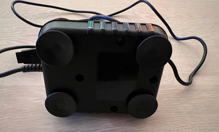
This should be an enjoyable refurbishment! It looks very nice from the outside - yes, it´s somewhat dirty - but it looks to be undamaged otherwise. I don´t yet know if it works yet, but from the looks of it I would guess the chances are good. This one also have a autofire feature - I´ve seen from time to time that the switch controlling the autofire is broken, but I think this will not be the case with this one. Time will show...
Also, the four suction cups looks also to be undamaged.
Refurbishment plan
To refurbish this joystick the plan is to do this trough the following steps:
- Clean, and remove stains from, chassis and all parts
- Clean the PCB
- Check connectivity
- Verify joystick operation by testing
Exterior chassis
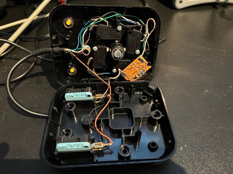
The plastic chassis consists of a top- and bottom cover. These are separated by removing the five screws at the bottom. This will expose the interior of the joystick.
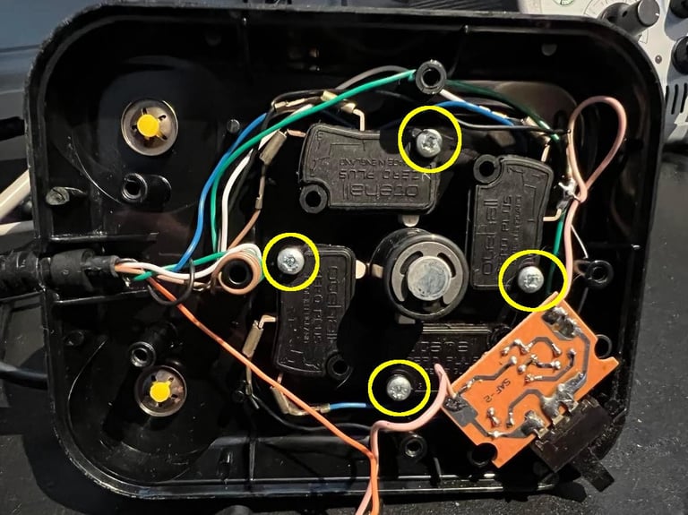
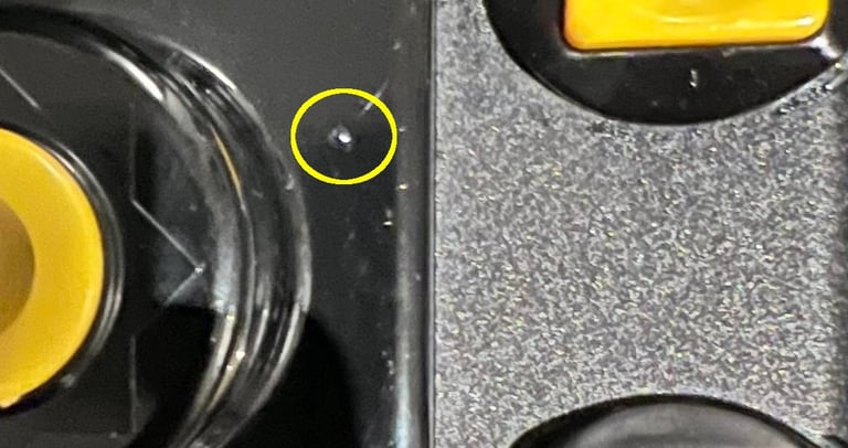
Next step is to remove the screws from the four microswitches. See picture below (circled areas).
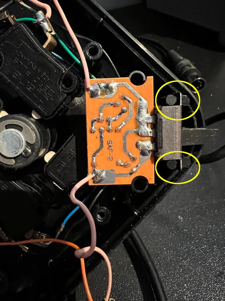
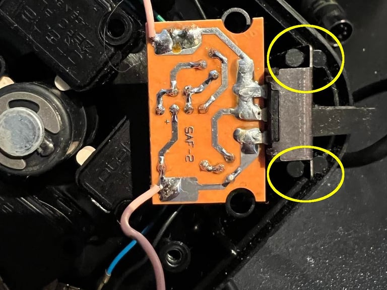
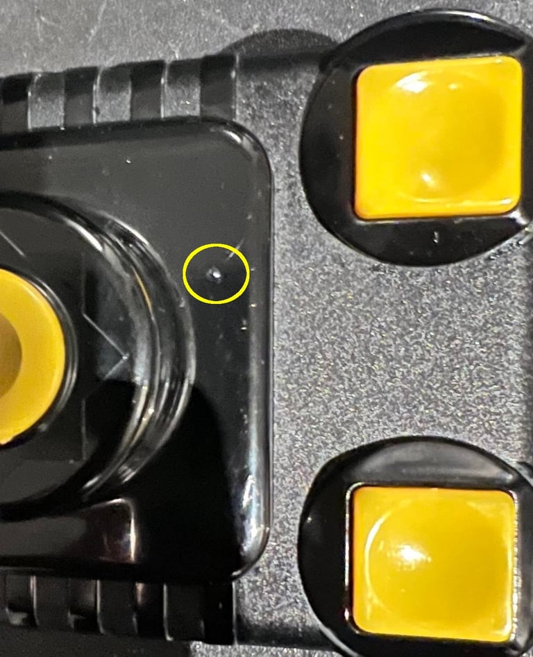
Then the little autofire PCB is removed. Note that the small clips holding this PCB can be brittle, so it is good to be careful when removing this (circled areas).
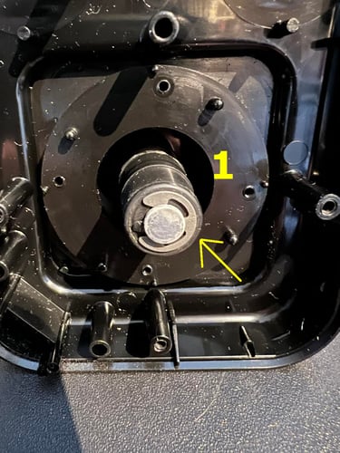
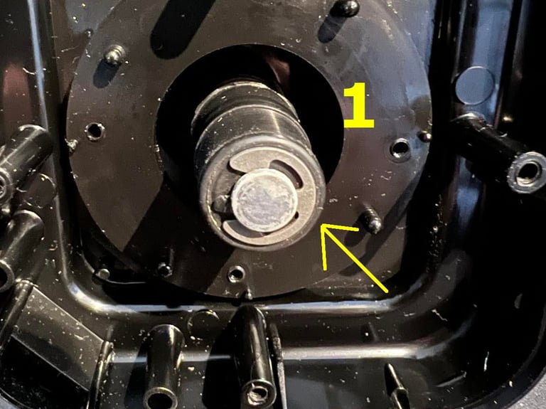
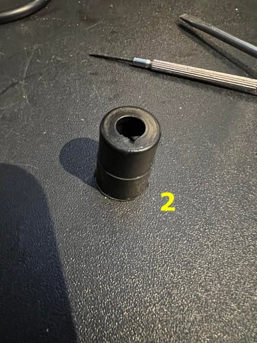
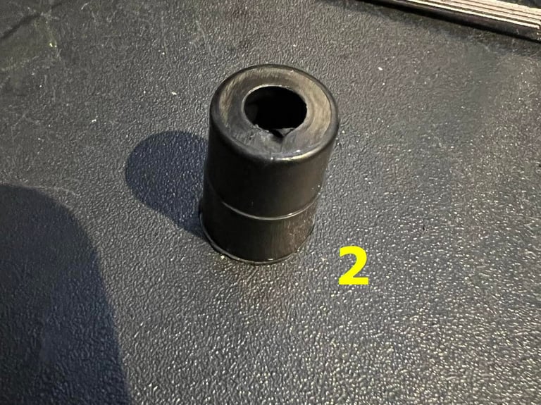
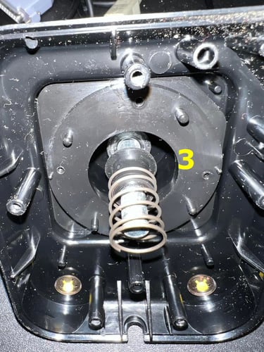
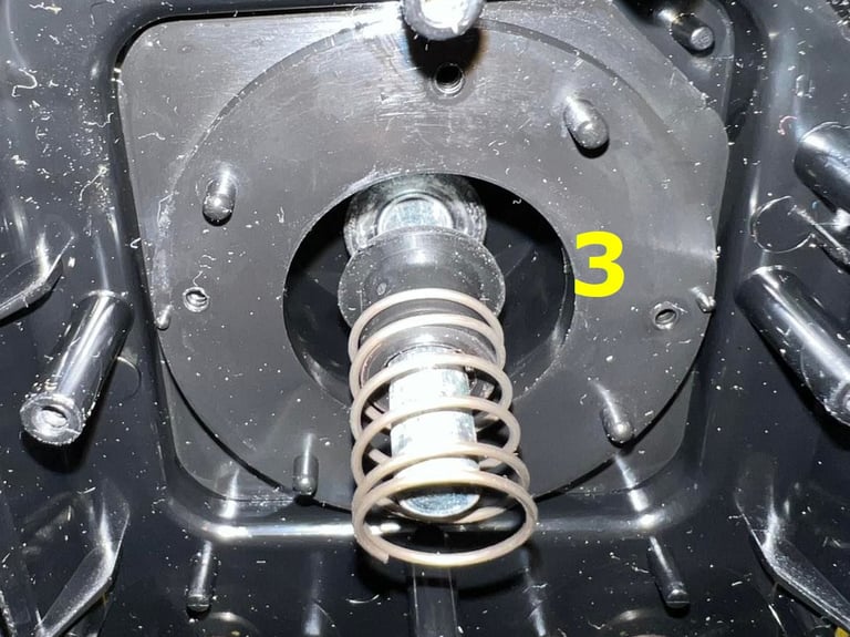
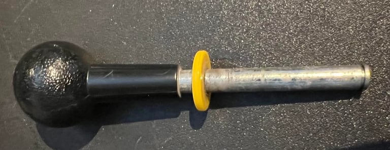
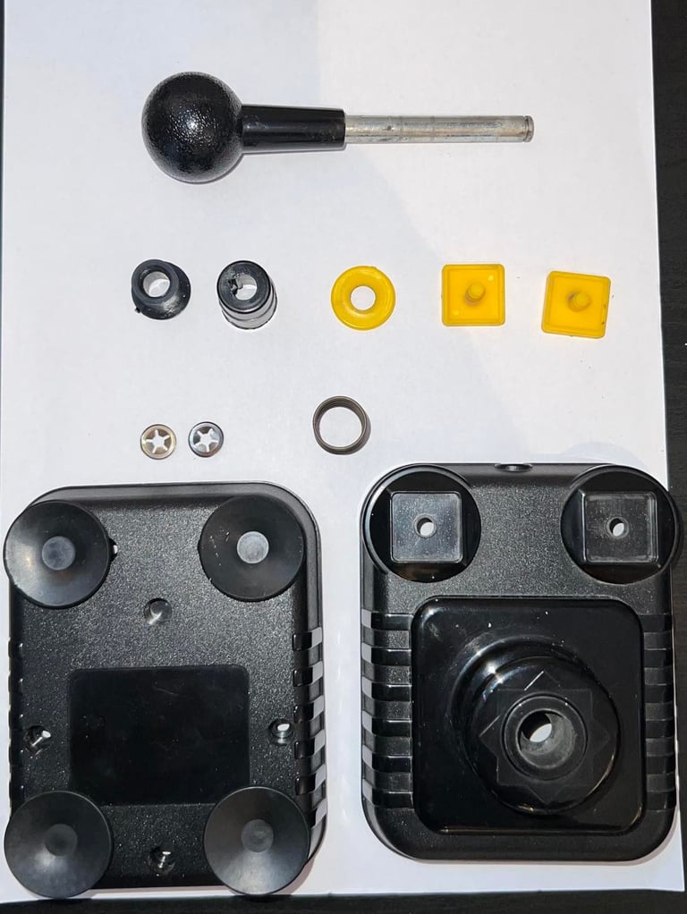
The joystick shaft is now ready to be removed for cleaning. To do this I first remove the small metal clip at the end of the shaft. This clip is shown marked as "1" in the picture below. I can now remove the first plastic cylinder - marked as "2". Last thing to do is to remove the spring and the last plastic cylinder - marked as "3".
The joystick is now completely disassembled - and all parts will be cleaned with some mild soap and water. Below is a picture of all the parts (ok, well, almost - the little metal clip at the end of the joystick shaft didn´t make it to the picture...).

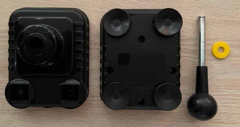
Below is a picture of some of the parts after cleaning.
I notice a tiny small white dot on the top cover. Not a big deal, but it´s there. Maybe it could be disguised with a black pen, but I think I´ll leave it.
Interior electronics and cable
Interior electronics are checked for corrosion and damage. And as far as I can see everything looks fine. The six microswitches seems to be functioning as they should. Nevertheless, all contacts and switches are sprayed and cleaned with contact cleaner.
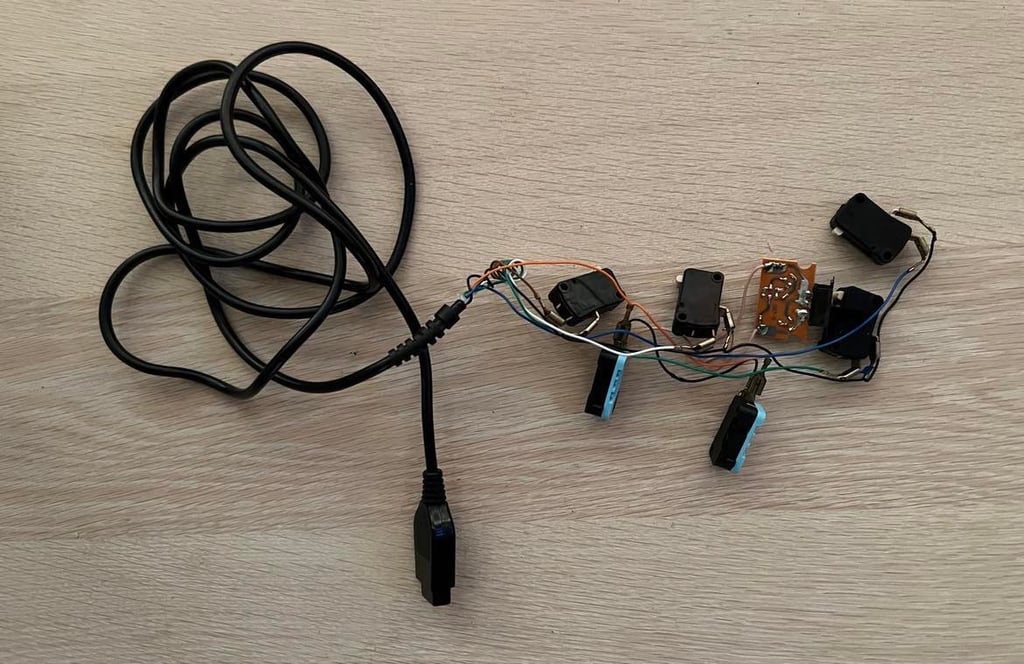

The cable and connectivity is checked with multimeter. All six wires (UP/DOWN/LEFT/RIGHT/FIRE/GND) show good connection also while I rotate and twist the cable. Note that there is no +5V wire directly connected to this joystick even if there is an autofire.
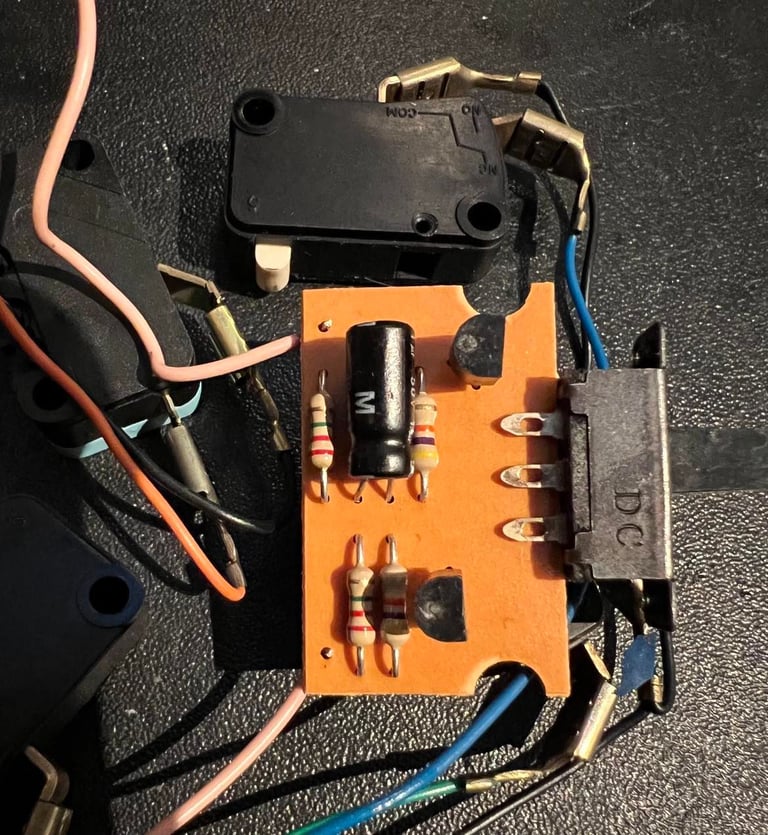
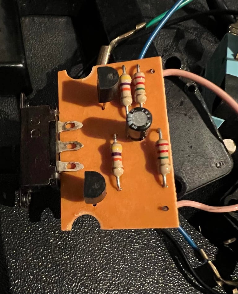
The autofire PCB is cleaned with isopropanol and checked for corrosion. The switch is also cleaned with contact spray, and the switch is checked. This autofire is somewhat different from other ZipSticks I´ve refurbished (e.g. this one). Insted of using a small IC such as a 555 timer, this one only use the combination of two transistors, some resistors and an electrolytic capacitors. The electrolytic capacitor is a 1 uF / 50 V - and this one is replaced with a new quality brand capacitor with the same capacitance and voltage rating. This is because this capacitor is almost 40 years and is likely to dry up which could cause the autofire to either malfunction or supply a wrong autofire frequency. The picture to the left shows the PCB with the old capacitor and to the right is the new capacitor installed.
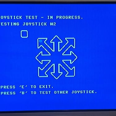
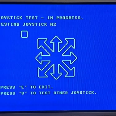
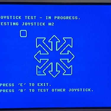
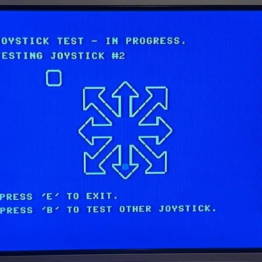
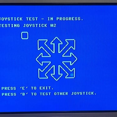
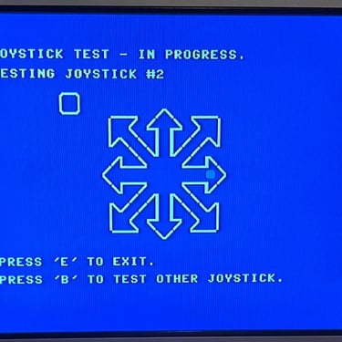
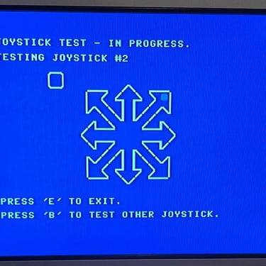
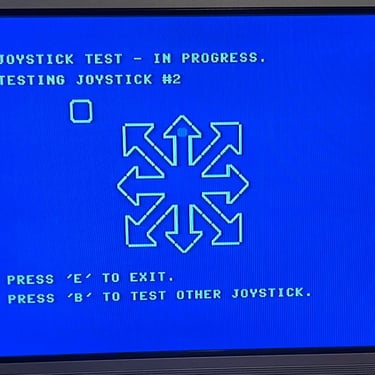
Testing
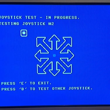
The joystick is tested using the 64 doctor software running on a real Commodore 64. All directions, fire button and autofire works as it should. Below are some pictures from the testing process.
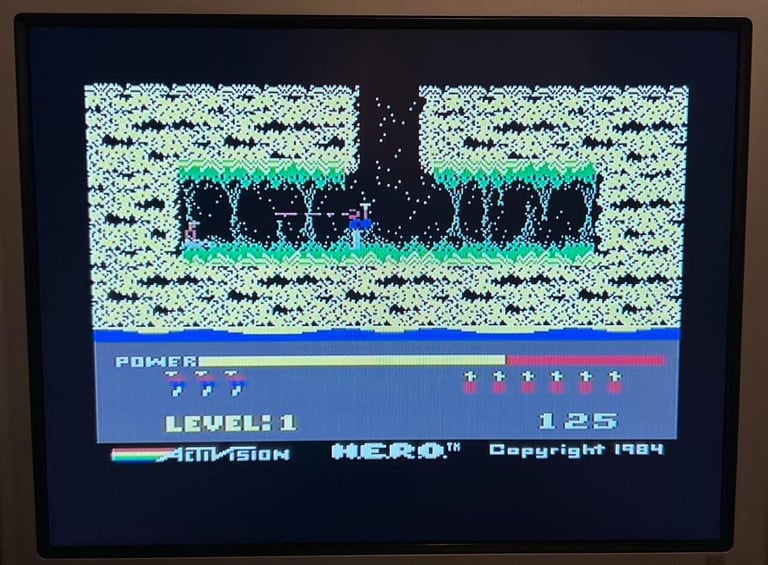
And of course the joystick is tested with some proper C64 games! Who doesn´t love H.E.R.O.?

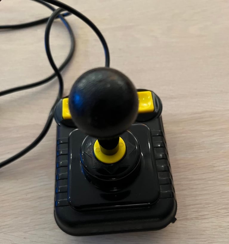
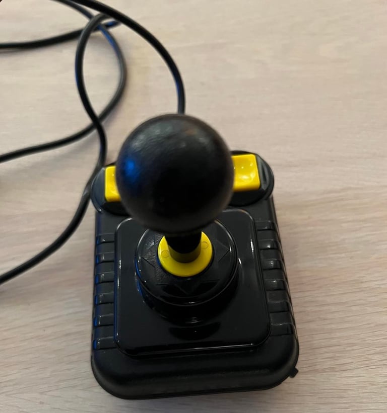
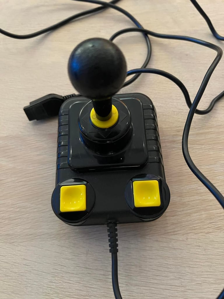
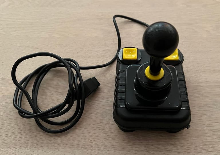
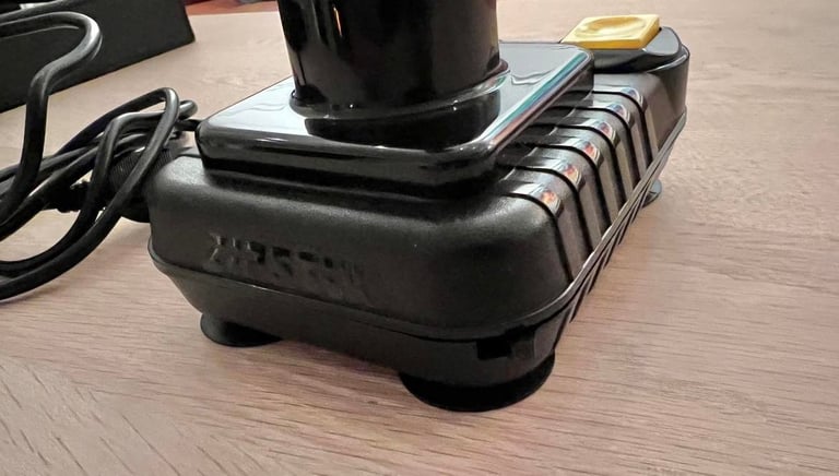
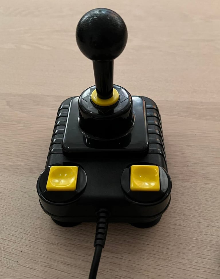
Final result
"A picture worth a thousand words"
Below is a collection of the final result from the refurbishment of this joystick. Hope you like it! Click to enlarge!

Banner picture credits: unknown