

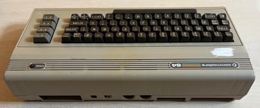
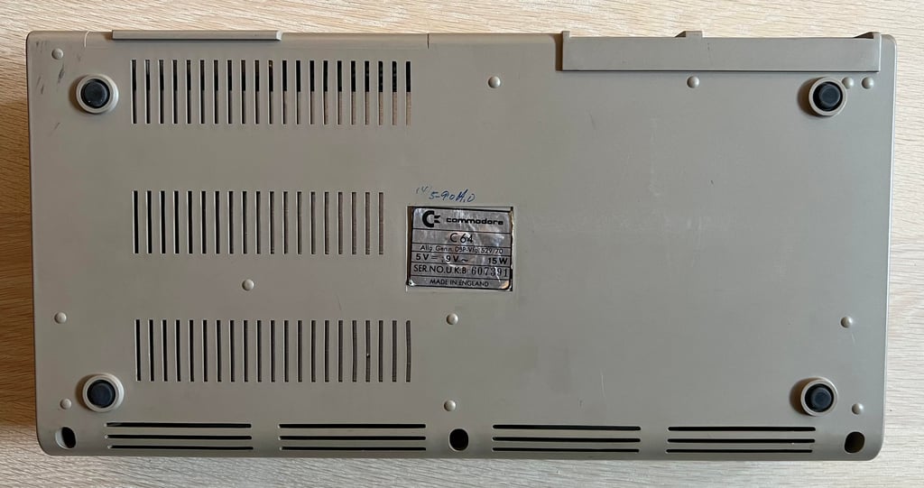
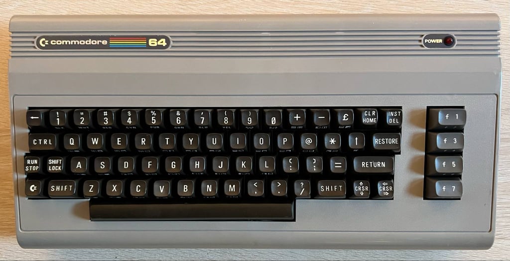
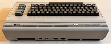
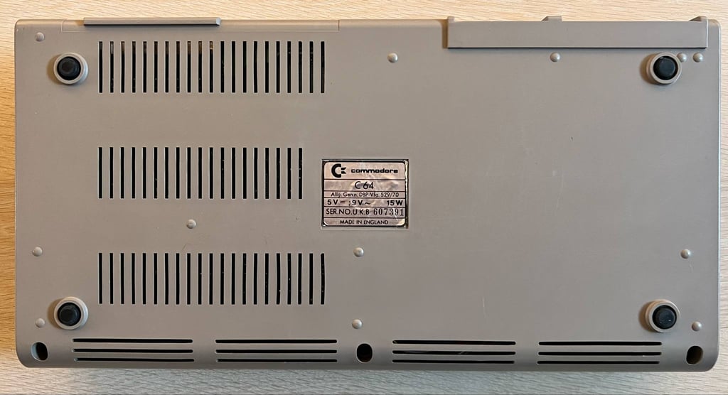
C64 Breadbin [PAL]
Ser. No. 607391
Assy 250407
Artwork 251137 (REV B)
Starting point
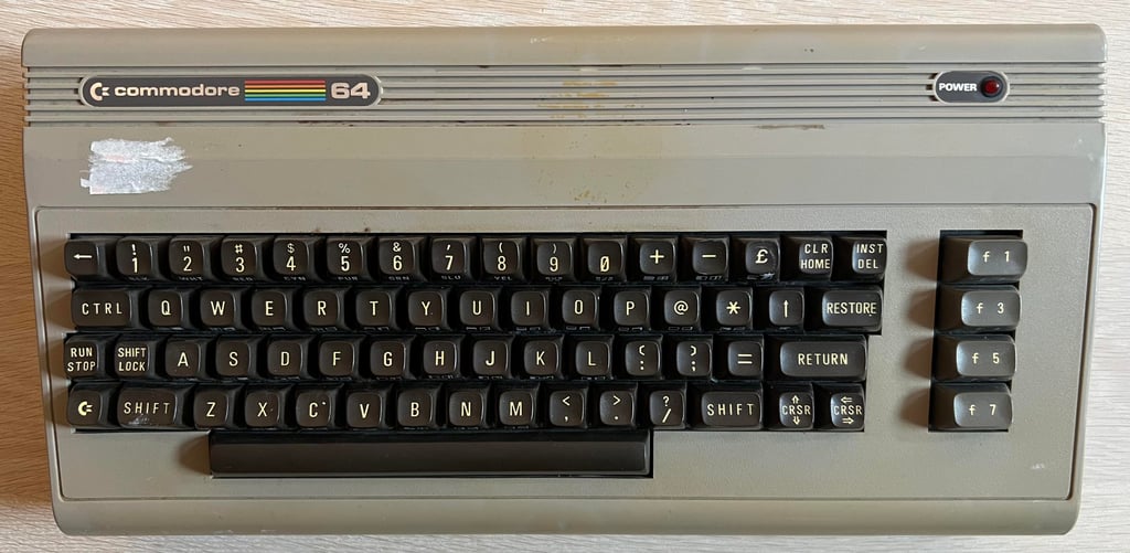
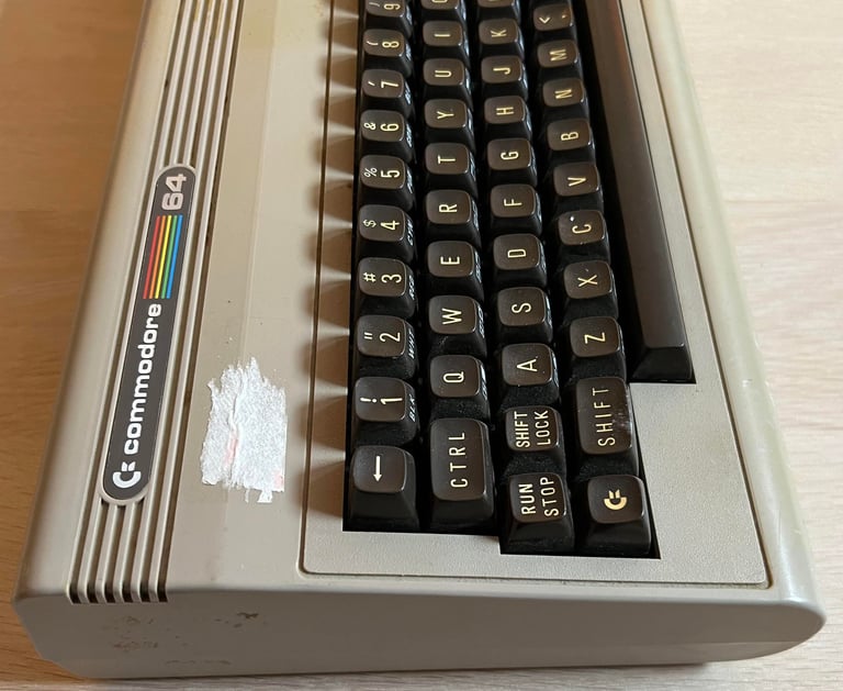
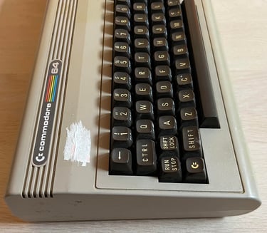
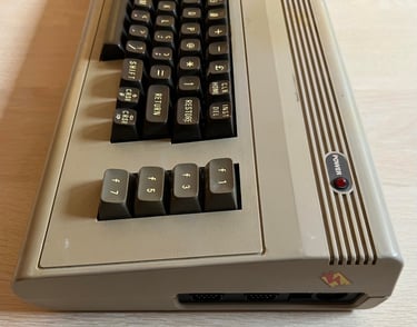
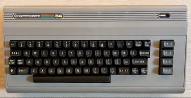
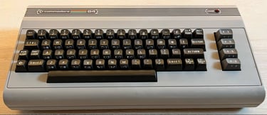
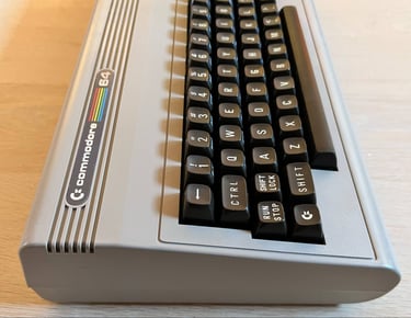
From the outside this machine appears to be in quite good condition. Yes, there is a lot of dirt, grease, stickers and residue of previously removed stickers. But when trying to see past these cosmetic issues the Commodore 64 breadbin looks ok. The keycaps, spring and plungers appear intact and I can not see any visual damage. There are some signs of use, but nothing serious I think.
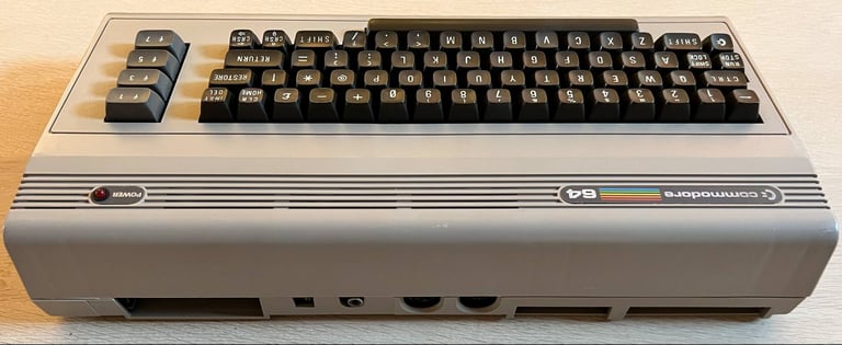
There is written something with a pen on the bottom cover: "14/5-90 A.O". Could this mean that a person with the initials A.O. repaired this machine the 14th May in 1990? Which is 34 years ago quite exactly since it is the 18th May when I write this.

Refurbishment plan
The refurbishment plan for this C64 breadbin (several of them in parallell):
- Refurbish the casing (cleaning, repairing and retrobrighting)
- Refurbish the keyboard (cleaning, reviving the plungers and retrobrighting)
- Refurbish main board (cleaning, checking, repairing, replacing capacitors and voltage regulators, adding heat sinks etc.)
- Recap RF-modulator
- Verify operation by testing
The plan can be updated during the refurbishment process. Sometimes I discover areas that needs special attention.
Disassembly
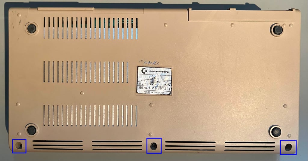
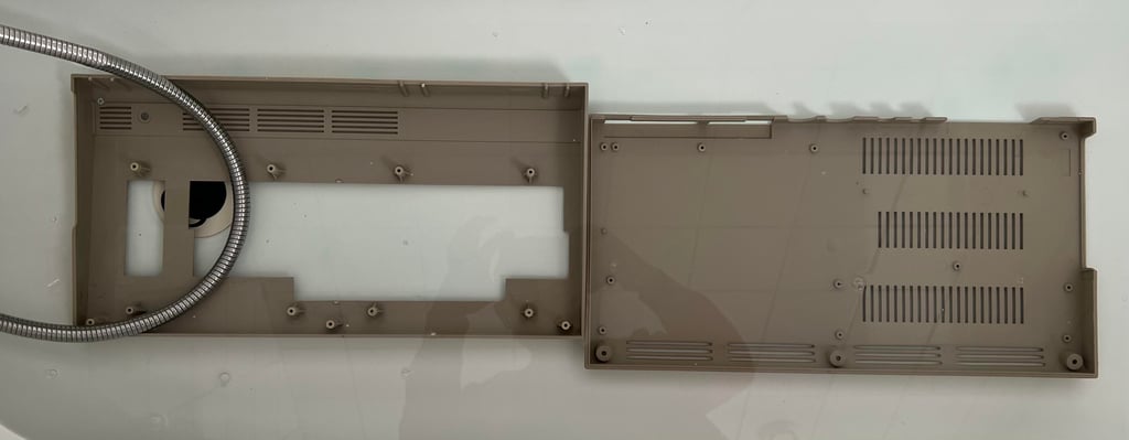
The Commodore 64 breadbin consists of a top- and a bottom cover which are held together by three screws and rear clips. First, the three screws are removed.

The top cover is lifted about 30 degrees and then carefully wiggled until the cover is loosened. This reveals the inside of the machine: there is some dirt and grease which is expected. There is also a quite large spot on the cardboard RF-shield which looks like some kind of liquid residue. But all-in-all the inside looks very good so far.
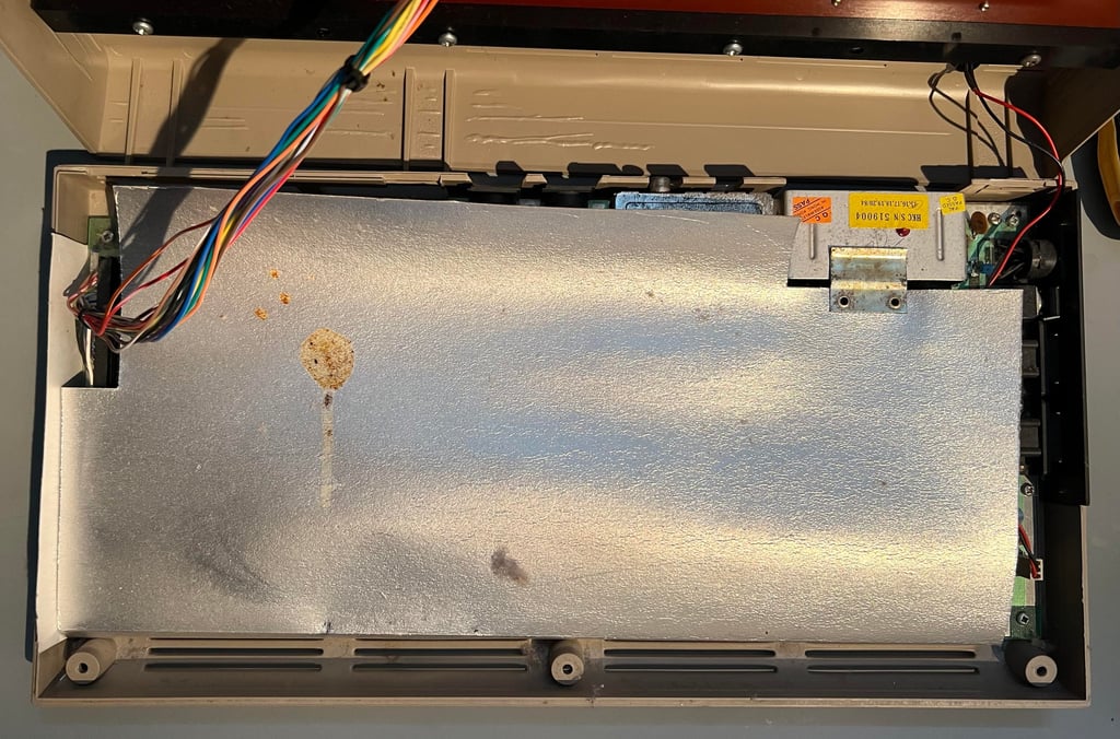
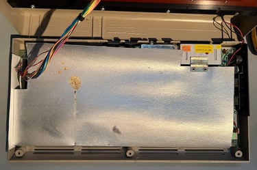
The RF-shield is lifted away and the mainboard is exposed. It looks to be in good condition by first glance. There is a significant amount of dust and grease, but otherwise no sign of any damage or missing ICs.
To remove the keyboard the eight screws are removed from the top cover. This will separate the keyboard from the top cover.
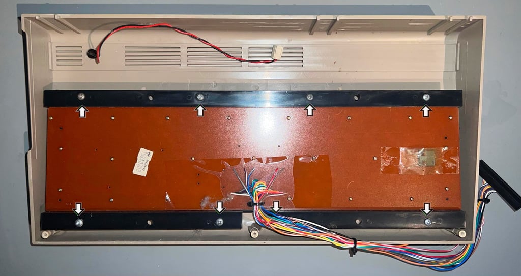

Exterior casing
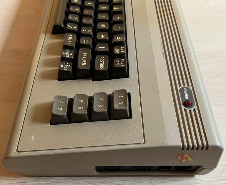
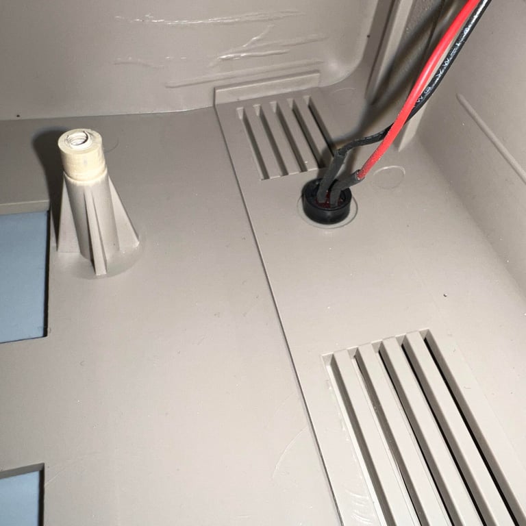
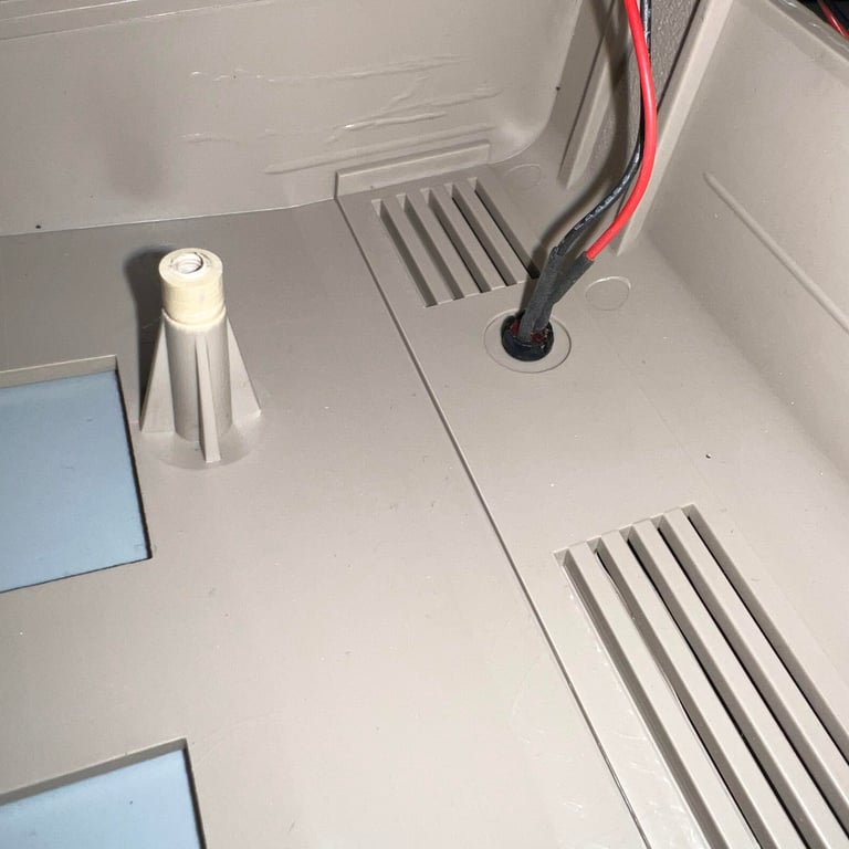
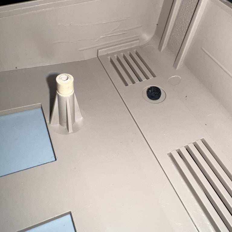
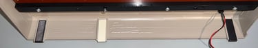
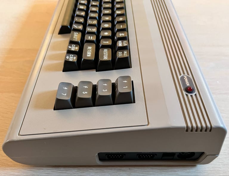
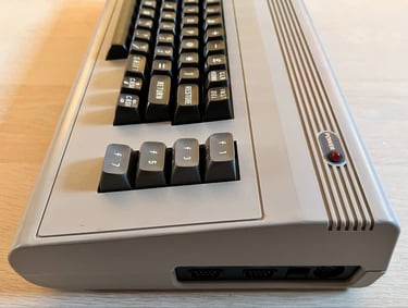
The covers are very dirty with stickers, grease and dust. Also, the covers appear slightly discoloured. But before cleaning the LED is removed. This is not a complicated operation, but it needs to be done in the right order: first remove the inner circular plastic ring, then firmly push the LED from the outside towards the inside and finally push and squeeze the plastic clip from the inside towards the outside. Below are some pictures from the process.
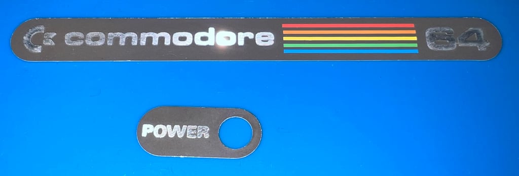
It is not strictly required, but I think it is good practice to remove the metal badges on the top cover before cleaning. This is to avoid any damage due to cleaning and retrobrighting later. To remove the metal badges some hot air from a hair dryer is used while the badges are carefully removed with a thin sharp knife.
Both the top- and bottom covers are placed in mild soap water for about 48 hours. This will remove most of the dust and grease.
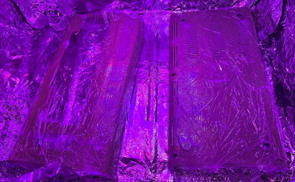
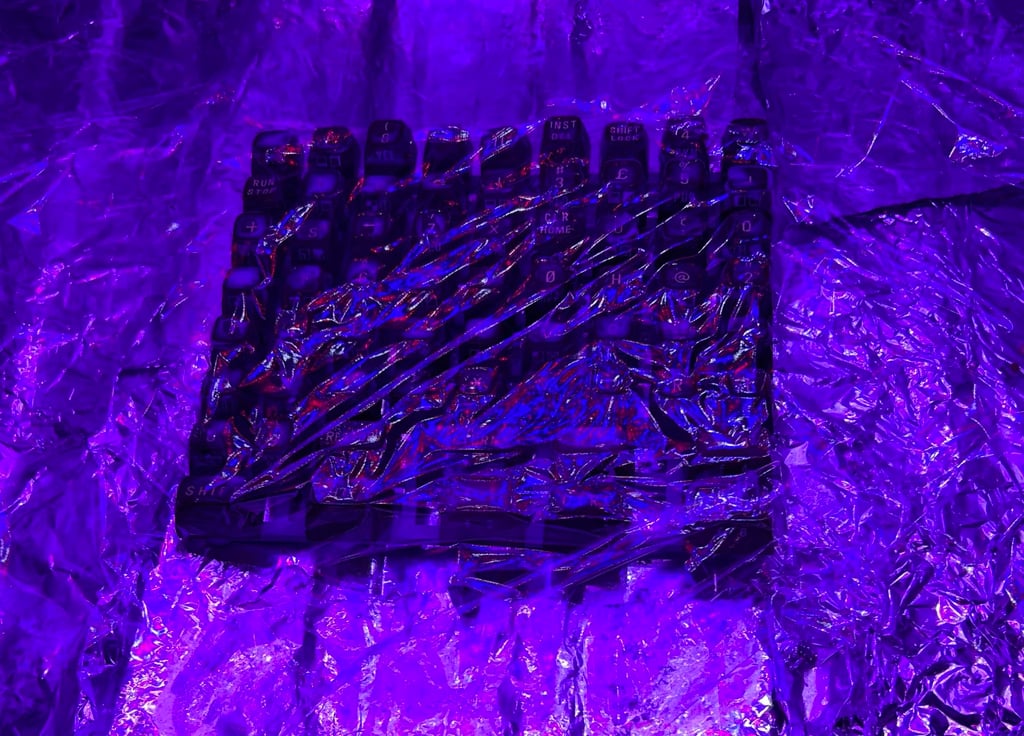
The covers are retrobrighted using 12 % hydrogen peroxide cream (smells really good! Hair salon!). During the retrobrighting, which is about 12 hours, more of the hydrogen peroxide cream is smeared on the covers. I am not sure if this is strictly required, but so far it seems to give a good result. The covers are wrapped in cling film and exposed to UV light during the retrobrighting.
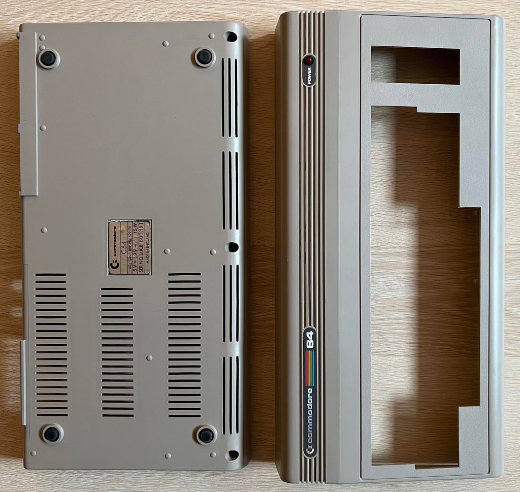
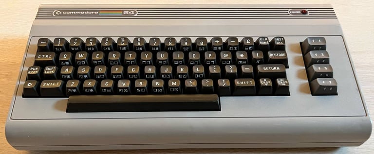
After a final cleaning and putting the metal badges back with some double sided tape, the covers looks very good. Almost as good as new (?).

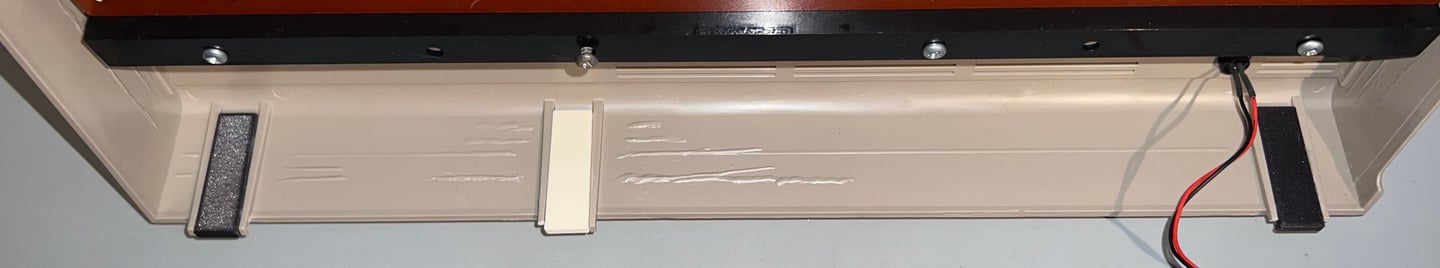
Some of the rear clips were partly broken. Luckily, these can be fixed by replacing them with some new 3D printed parts. I use some great parts designed by maralb1970. The new 3D printed parts are glued with super-glue.
Keyboard
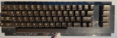
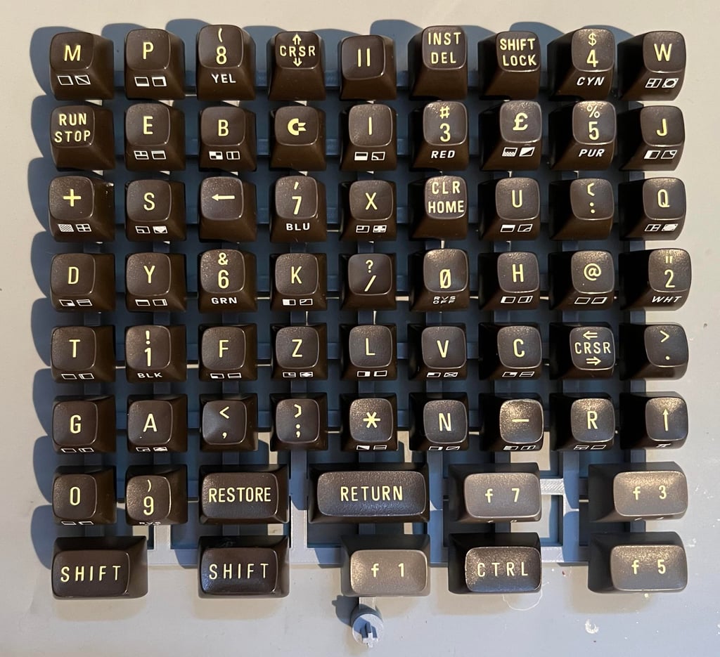
A working keyboard is essential for a great Commodore 64 experience. But in addition to be functioning, the keyboard also should be inviting to be used. And this keyboard does not. The picture does not give justice to how dirty this keyboard is. It is literally full of dirt and grease... yikes!

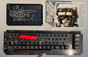
The first thing to do is to remove all the keycaps. This is done by using a keycap puller. It is highly recommended to use a keycap puller, first and foremost to prevent the plunger and keycap to be damaged, but also to avoid hurting your fingers. You can pull the keycaps off with your fingers, but it will hurt... Note that the spring beneath the space bar is slightly larger than the rest. So it is good practice to keep this spring in a separate plastic bag to avoid mix up.

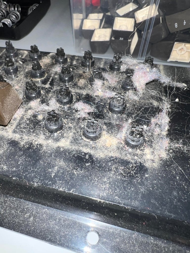
Just to show how REALLY dirty this keyboard is a close-up picture is taken with blitz. Oh my...

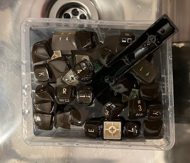
All the keycaps are placed in a box filled with mild soap water for about 48 hours. This is to make sure that all the grease and fat are removed from the keycaps. Having properly cleaned keycaps is essential for a successful retrobright.

The SHIFT-LOCK key needs to be removed also. This is very easy (when you know how to do it). First the two uninsulated wires are desoldered. Note that also the back of the keyboard is very dirty - this will be cleaned later. Then the SHIFT-LOCK key is pushed firmly from the back side towards the front. This will make the SHIFT-LOCK key pop out of the keyboard holder.

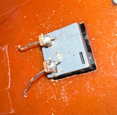
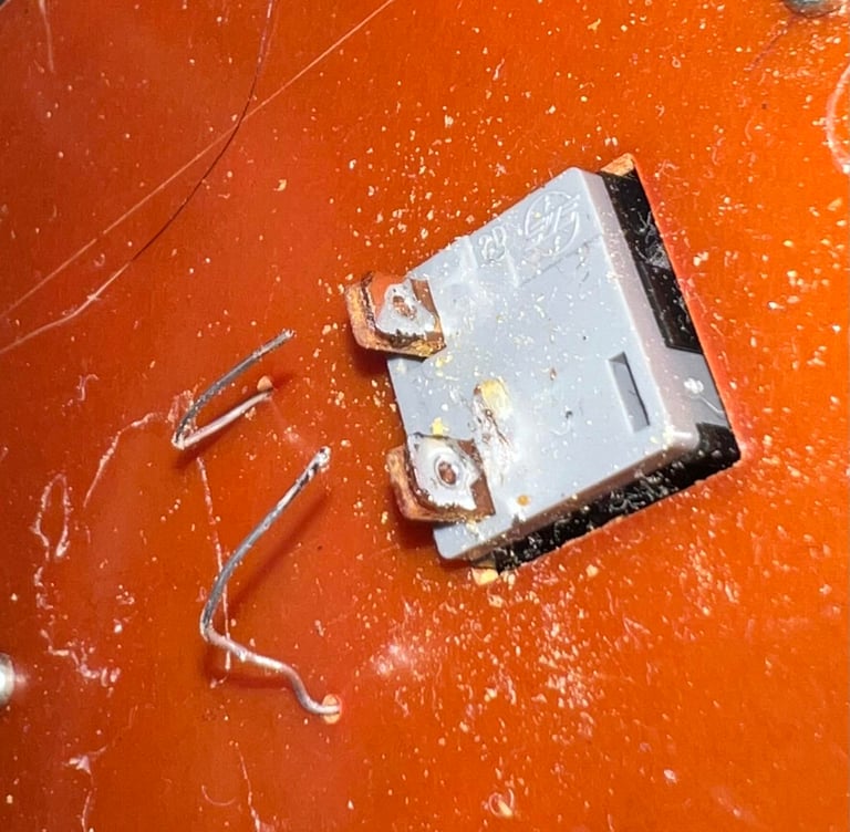
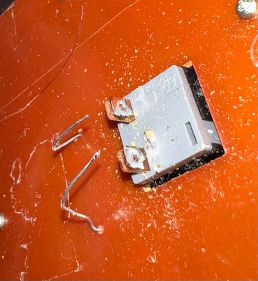
Since the SHIFT-LOCK key is also covered with dust and grease it is properly cleaned with isopropanol. After the cleaning the SHIFT-LOCK looks as good as new!

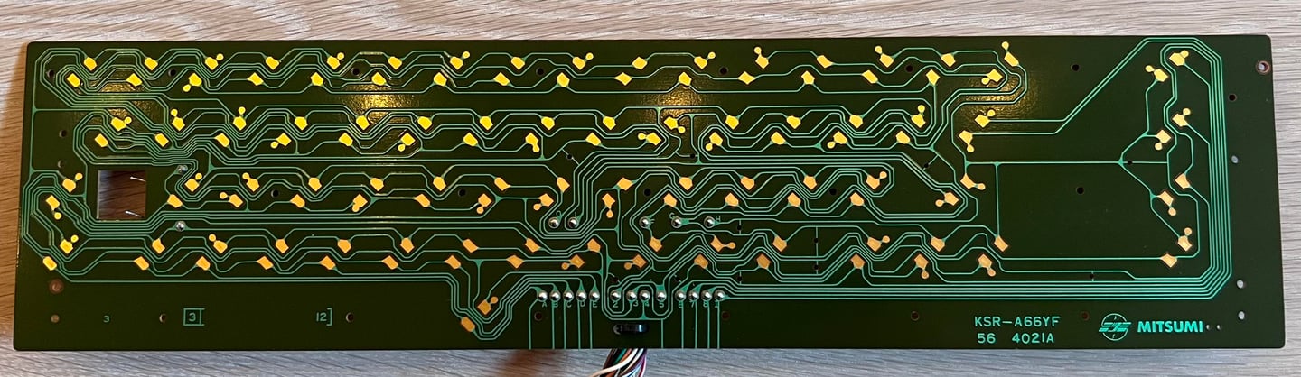
The backside of the keyboard, which is the keyboard PCB, is a Mitsumi KSR-A66YF (56 4021 A). This PCB is the version with the gold plated contacts (compared to the 4021B which has the carbon pads). Since there are no carbon pads on this one, the PCB is properly cleaned with some isopropanol. It looks very good after cleaning, and there are no sign of any damage or corrosion.
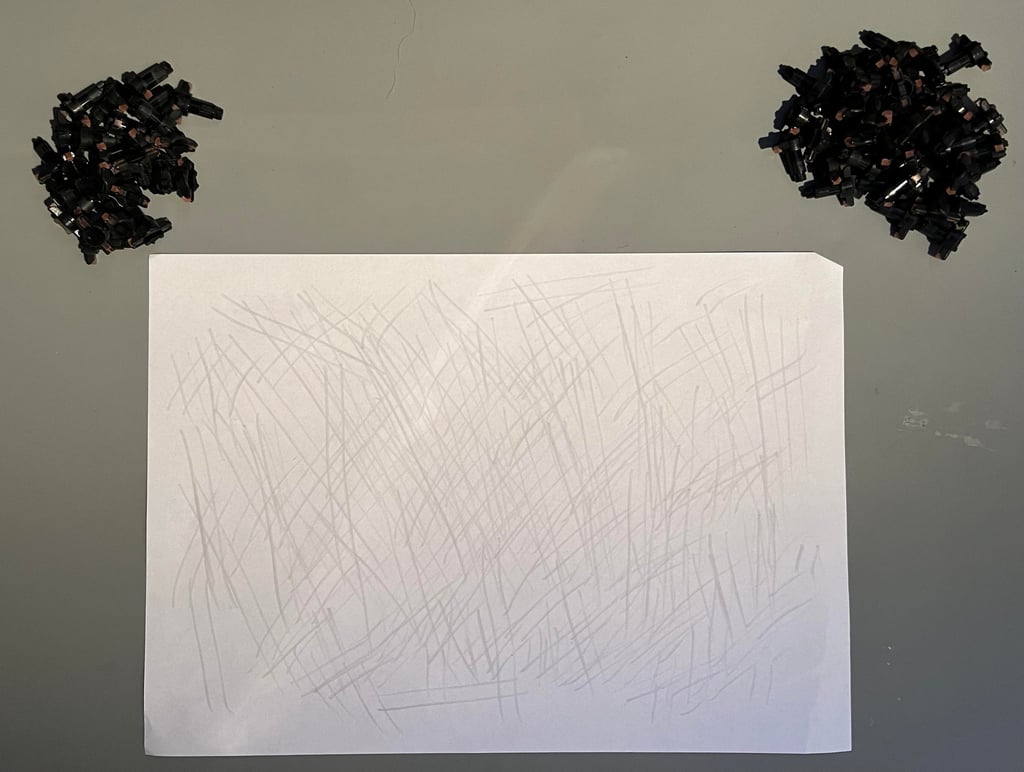
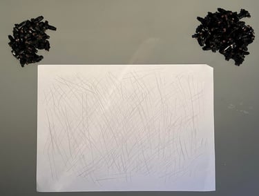
We all know the feeling of of keys need working. Or working, but you need to hammer the keys to get any kind of response on the screen. Luckily, this can often be fixed by reviving the key plungers. The plungers have a small conductive rubber at the end, and this rubber can get contaminated after years of use and storage. By carefully dragging them over a clean sheet of paper most of the fat and grease can be removed - and most of the time the plungers are brought back to glory. If this method does not work it is also possible to try with some isopropanpol, but this can damage the rubber so it best to try without first. Note also that this keyboard use plungers with the ~3mm tip.
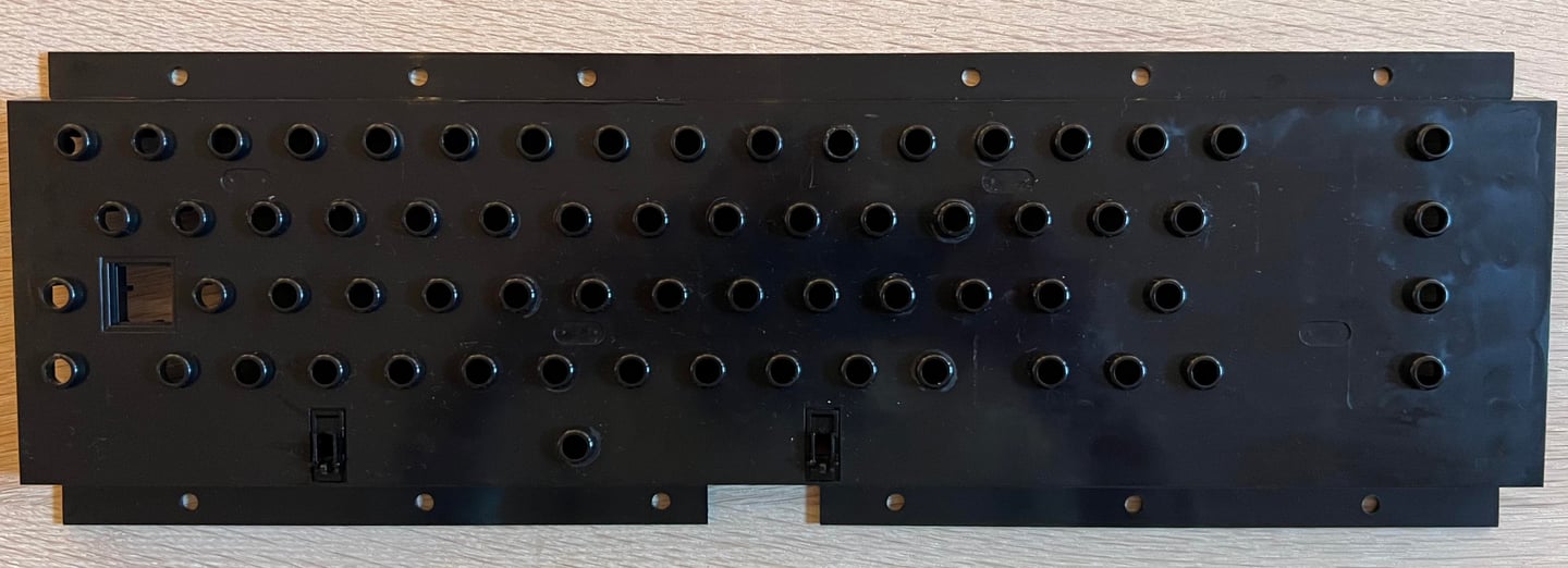
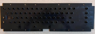
The plastic holder for all the plungers are cleaned properly with mild soap water - and then some isopropanol. It is really filthy, but after cleaning it looks as new! Magnificent!
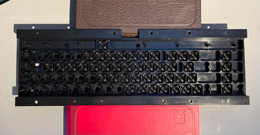
A little trick when re-installing the revived plungers is to lift the plastic holder with a few books. This will make it easier to drop all the plungers back in place.

The letter on the top of the keycaps are quite yellowed so some retrobrighting is required. All the keycaps are placed on a 3D printed bracket, and then 12 % hydrogen peroxide cream is applied on the keycaps. The keycaps are exposed to UV light for about 14 hours while fresh hydrogen peroxide cream is applied regularly.


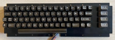
After retrobrighting and a final cleaning the keyboard is re-assembled. And the result is very good I think!

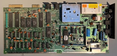
Mainboard
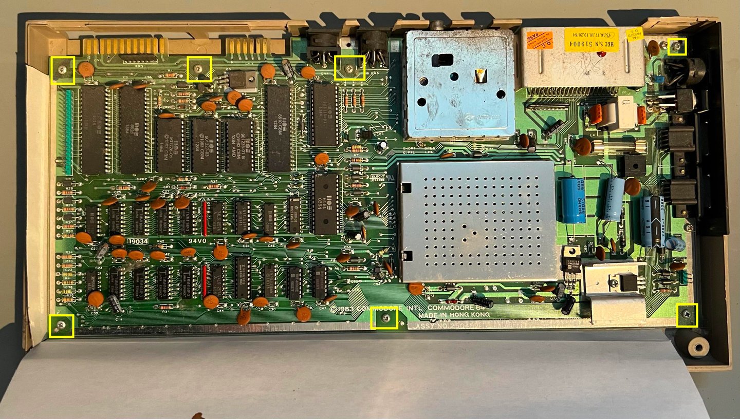
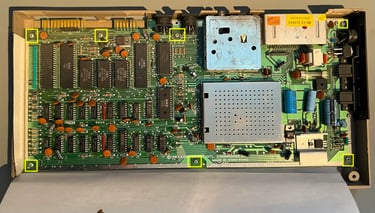
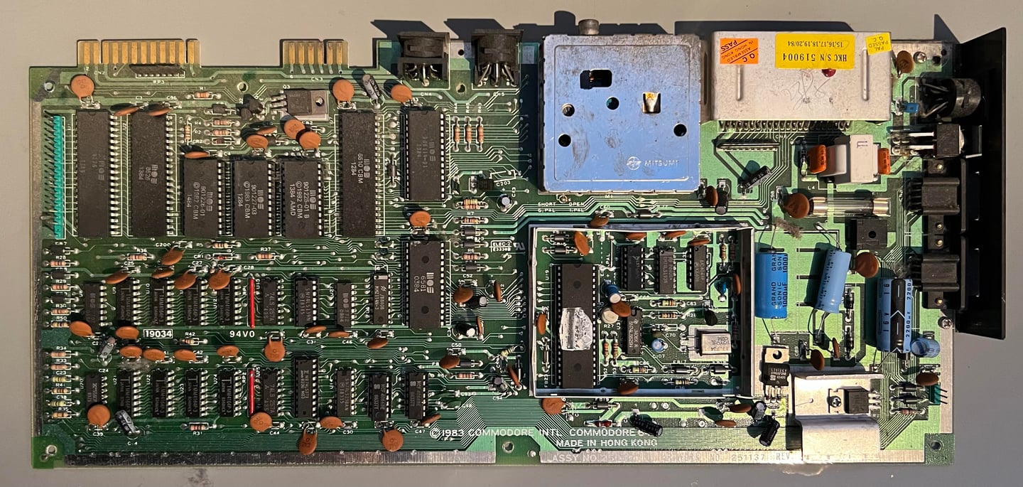
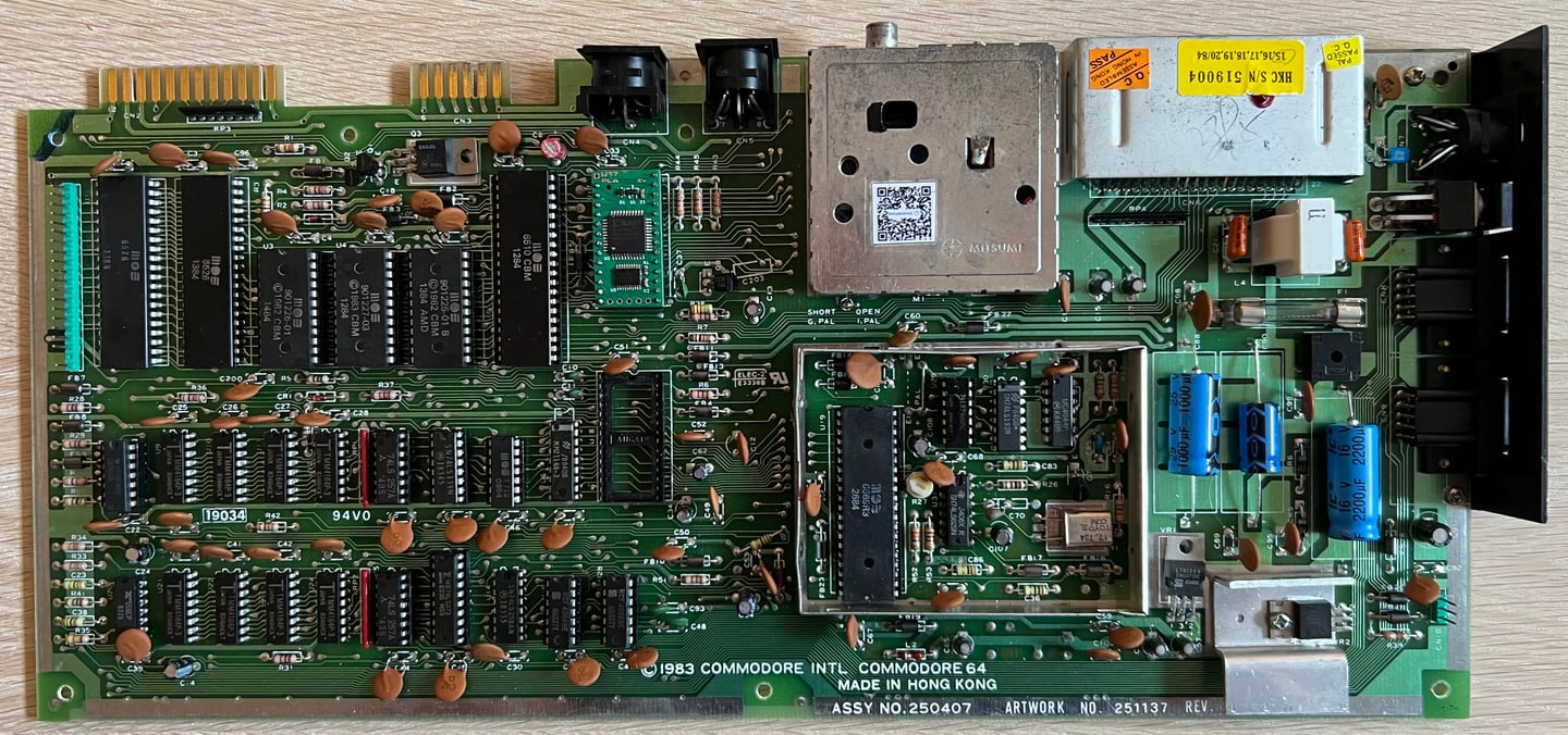
This is mainboard is an Assy 250407 / Artwork 251137 (Rev B) longboard. It is quite dirty: lot of dust bunnies and grease.
Visual inspection
There is quite a lot of dirt and grease on the mainboard. But that is to be expected after 30+ years. The 470 uF electrolytic capacitor (C90) seems to be... thrown into place at assembly time? The legs are obviously too long and bent, but it does not appear to be broken. The C90 capacitor is used in the circuitry converting the 9 VAC to 12 VDC via the 7812 voltage regulator.
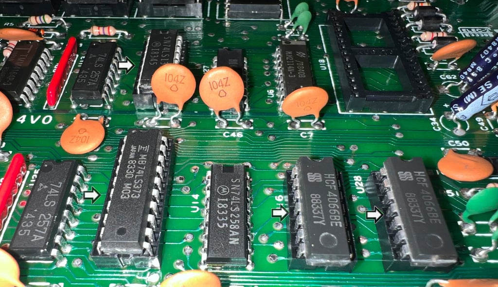
Several of the ICs are socketed. It is not uncommon that the custom ICs such as the ROMs, PLA, SID etc. are socketed, but that some of the glue logic chips are socketed is not common. On the mainboard the glue logic ICs U26, U16, U28,U15 and U29 are all socketed. This makes me think that this machine has been repaired at some point in time. But I can not see any obvious sign of rework on the backside of the PCBA in these socketed areas - I can not see any difference between the solder points beneath the socketed chips and the rest. And no sign of flux residue on these areas either. So that makes me guess that either:
The glue logic sockets were installed due to sourcing issues. Some ICs were missing at production time, but the complete PCBA were made but placed on-hold until the remaining ICs were sourced and then installed afterwards in the sockets. Or...
The glue logics were defect either at first testing in the factory or later, and the repair was done professionally
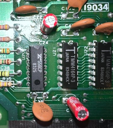
In the table below the custom ICs are listed.
As can be seen from the table above the custom ICs were produced between week 3 to 14 in 1984. And it is fair to assume that the Commodore 64 was assembled in the spring of 1984 - perhaps while all workers at the assembly line were listening to Lionel Richies "Hello" song on the radio?
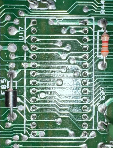
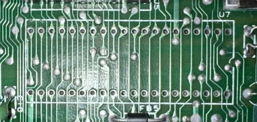
It is also worth mentioning that the socketed glue logic seems to be produced earlier than the custom ICs. I am not sure I read the date codes correct on these glue logic ICs, but it seems like that they were produced between week 30 to 45 of 1983. Below are some pictures of the socketed glue logic. Repair or sourcing issue? I don´t know...
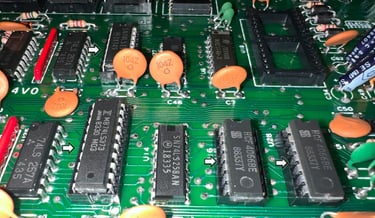
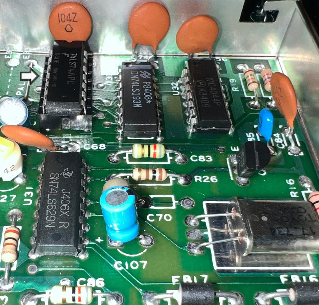

There are some MOS glue logic:
MOS 7707 (U8) - Hex Inverter Buffer
MOS 7712 (U27) - Quad 2-input AND gate
The MOS 77xx glue logic is notorious for failing. Even if these might be OK today, they are very likely to fail. So these will be replaced with modern 74xx IC during refurbishing.
Initial testing
Before the machine is powered on for the first time a check for short circuit on the +5V DC and 9 V AC power rail is performed. This is easy to check at the user port – see the article of Checking the C64 voltages for the position of these. Luckily, there are no short circuit so it should be safe to power on.
Powering on the Commodore 64 results in a: BLACK SCREEN - WITHOUT ANY VIDEO SIGNAL.
Not very surprising since these machines are getting quite old, but it now means that repair is required. Note that the screen is REALLY black. There is absolutely no video signal at all coming out from the A/V port to the TV.
Checking the voltages
For the Commodore 64 to work flawlessly all the different voltages need to present and within acceptable tolerances. A detailed article on the subject can be found in the HOWTO - Checking the C64 voltages. In the table below all the measures voltages are listed (this list will also be updated after refurbishment). All the required voltages are present and within tolerances, so there are nothing obvious wrong in that area. NOTE: for those who follow my refurbish project you may notice that many of the voltages appear lower than seen before. The voltages are completely fine, but I am now using a modified C128 PSU which outputs a bit lower voltages - but it is well within tolerances.
Mainboard - Repair
Since all voltages appear to be both present and within acceptable levels the supply of power does not seem to be the problem. The VIC-II which is responsible for generating the video signals COLOR and S/LUM (and also the clock used by the CPU) the MOS 6569 VIC-II seems to be a likely culprit.
Hot ICs (and Dead Test Cartridge)
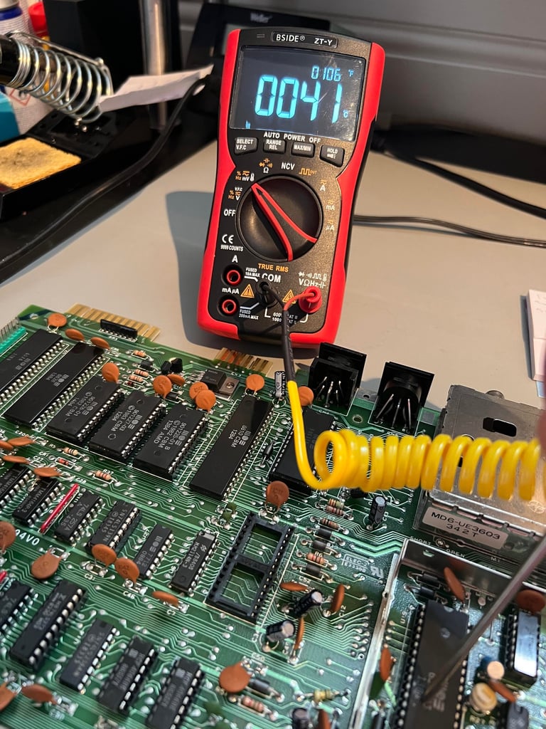
A good starting point for fault finding is to check for hot ICs and to run the Dead Test Cartridge. But since there is no video output at all the Dead Test does not bring any value yet.
When checking for hot ICs there is one chip which is significantly hotter than the rest: the MOS 6569 VIC-II. It is normal for the VIC-II to run very hot during operation, and I do not think that this is warmer than normal. After about five minutes the registered temperature on the VIC-II chip is 41 degrees celsius (although I do not think that this reading is very accurate).

Checking the PHIN, PHCL, PH0, COLOR, S/LUM signals
The VIC-II is responsible for generating the PH0 signal which is used as the clock for the 6510 CPU. To do this a 17.734 MHz crystal is used in combination with some some glue logic chips. But to verify that the clock input is present the PHIN and PHCL lines are checked. The both look normal as can be seen from the pictures below (compared to the reference signals for the VIC-II).


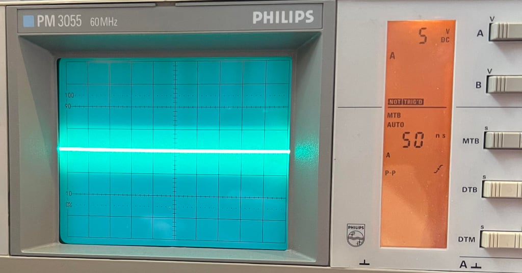
When checking the PH0, the 985.248 kHz clock used by the 6510 CPU, it turns out that there is no activity here. The signal is dead flat 0 volts. So this Commodore 64 would never run - even if there was a video output - there is simply no clock.

Just to verify that there is no analog video output COLOR (PIN #14) and S/LUM (PIN #15) are checked. They are both dead flat, but COLOR is stuck high at +5 VDC and S/LUM is stuck low at 0 VDC.
So my guess is that this 6569 VIC-II gave up the ghosts...
Replacing the 6569 VIC-II
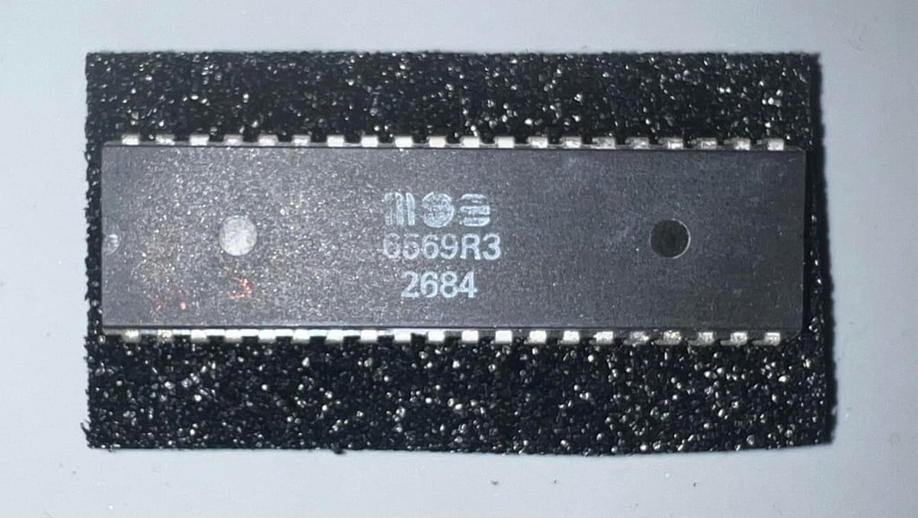
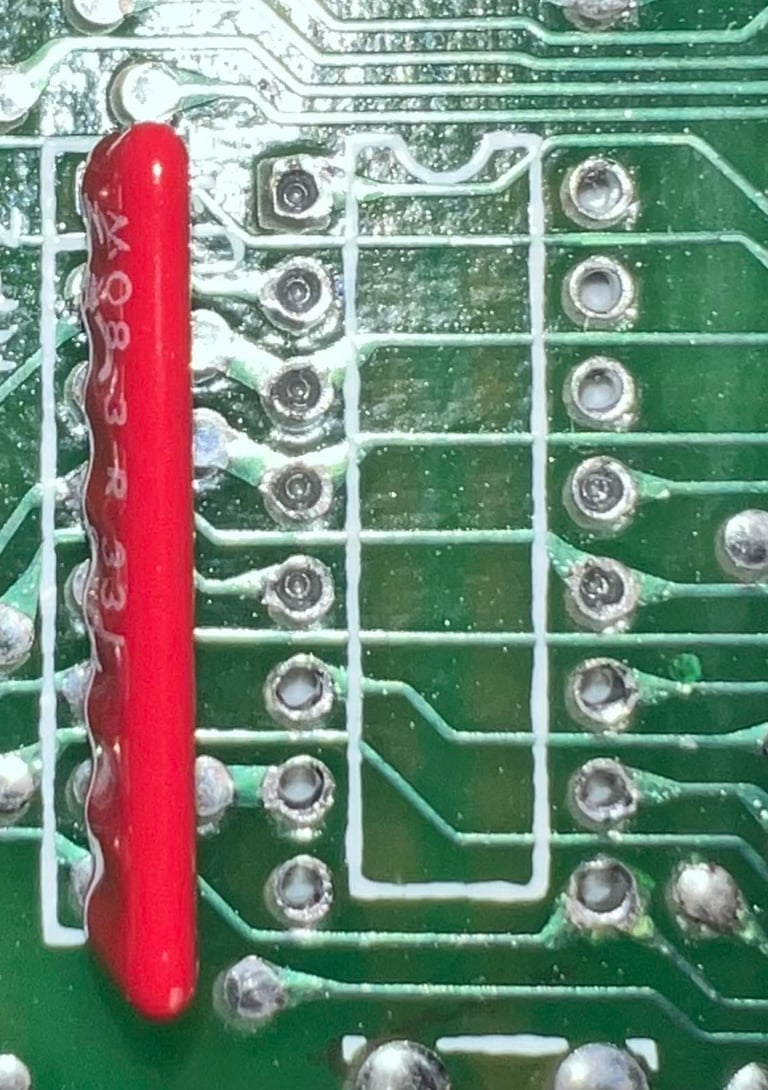
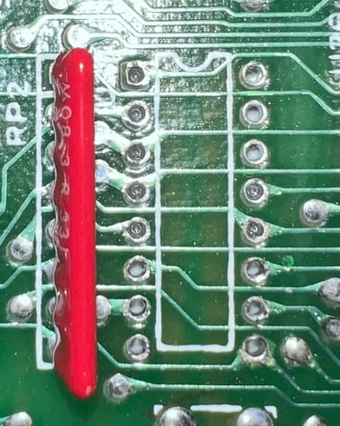
A new MOS 6569 VIC-II R3 is sourced from retroleum.co.uk. This one has the date code of week 26 of 1984 - same year as the rest of the cusom ICs.
With the new VIC-II chip in place the machine is powered on and tested. The result is:
BLACK SCREEN - WITH VIDEO SIGNAL
Ok, so this is good. Not that is good in any way with a dead VIC-II as these are becoming harder to source, but now we are making progress. The missing signals (PH0, COLOR, S/LUM) are checked again.
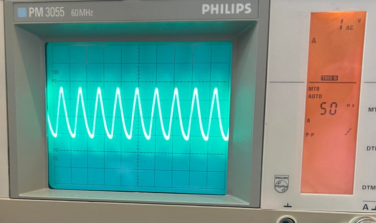
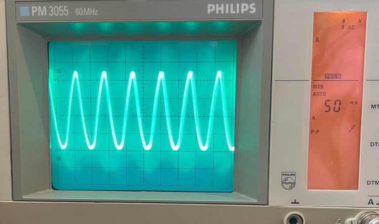
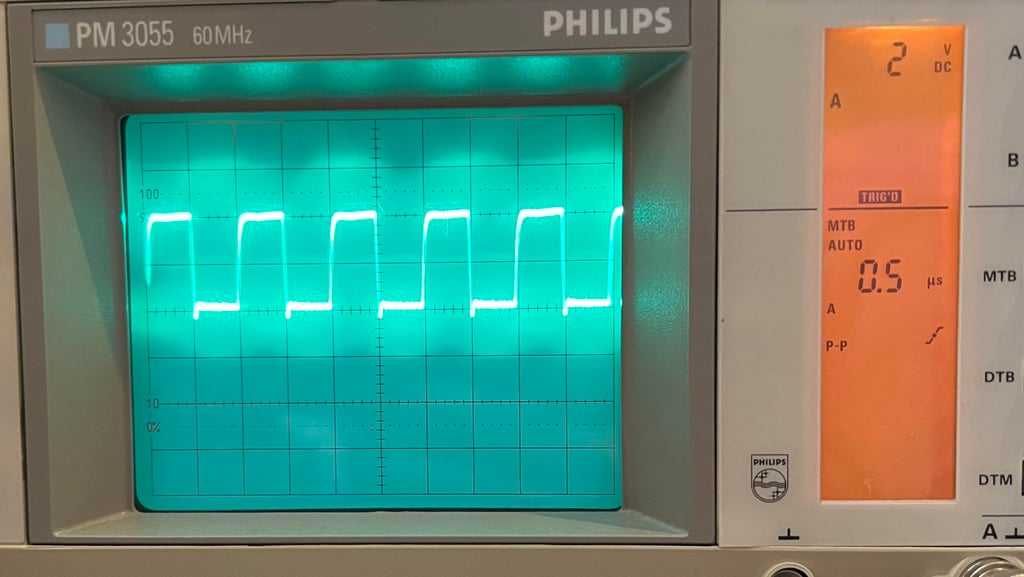
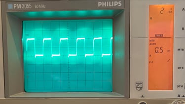
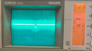
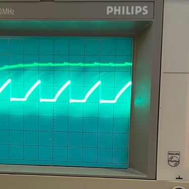
First the PH0 clock signal is checked. As can be seen from the picture below we now have a stable clock pulse of about 1 MHhz. The scope is set to 2 V/DIV and 0.5 uS/DIV. Since this is an analoge oscilloscope we need to calculate the frequency by our selves: 1 / (5*0.5*10-6) = 1 MHz. With 2 V/DIV the peak-to-peak is about 4 V which is fine.
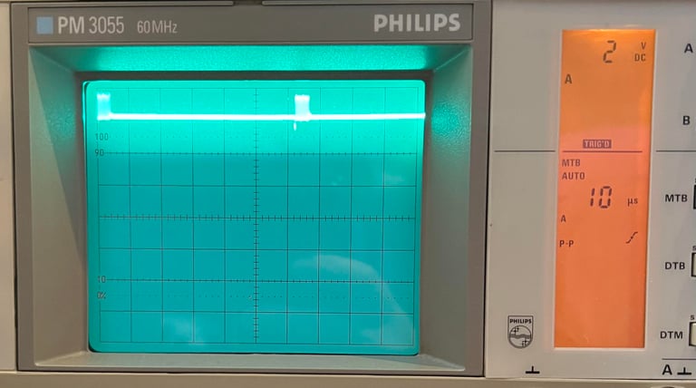
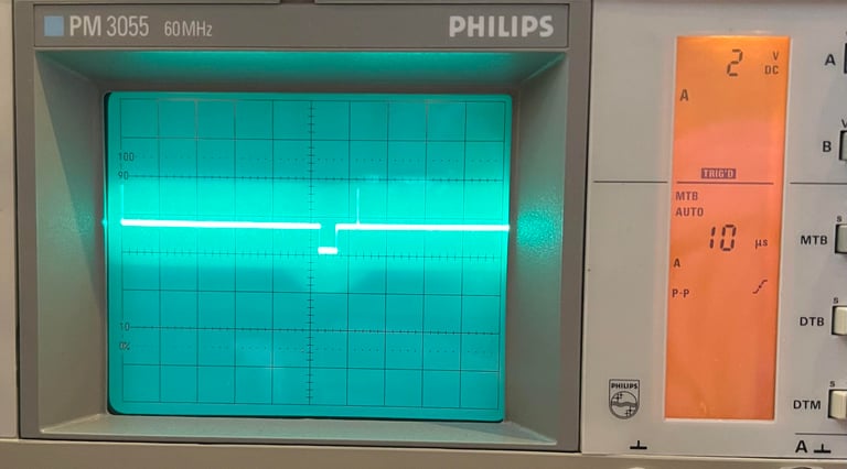
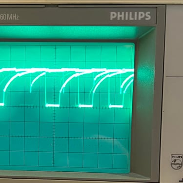
The Commodore 64 seems to produce a video signal (black) now, but it is good practice to check with an oscilloscope that the correct signals on COLOR (PIN #14) and S/LUM (PIN #15) are present. There is not much information on the screen (only black) so both the COLOR and S/LUM signal does not contain much signalling, but as can be seen from the pictures below they appear to be ok. For reference how these signals look with the default blue screen please see reference signals for the VIC-II.

Dead test , 77xx ICs and RESET signal
Now that the VIC-II is working there is a chance that the Dead Test Cartridge can give some more information about the next fault. The Dead Test Cartridge does not need all ICs to be working. There are some ICs such as the CPU, VIC-II and PLA which are required, but the ROMs are not. Therefore both the BASIC-, KERNAL- and Charset ROM are removed since these are socketed. This is to rule out that any of these are preventing the Commodore 64 from booting.
With the Dead Test Cartridge the Commodore 64 shows... NOTHING! There is still black screen.
As mentioned the MOS77xx logic ICs are notorious for failing. They will be replaced later in the refurbishment, but they are checked with the oscilloscope to see if these are working or not. The MOS 7707 is equivalent to TTL 7406 which is a hex inverter IC. And the MOS 7712 is equivalent to TTL 74LS08 which is a quad AND gate. It turns out that none of these seems to be faulty. All signals looks perfectly fine.
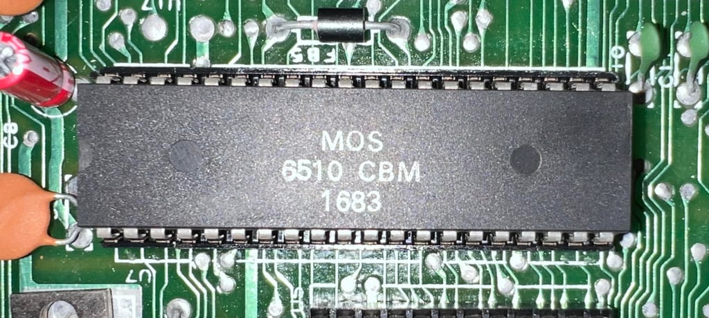
The /RES signal on the MOS 6510 is checked. This signal should stay low a short period before being pulled to +5V. The signal can be found on PIN #40 on the CPU. It turns out that this signal is ok.
Checking the and replacing PLA
An IC which is notorious for failing on the Commodore 64 is the PLA chip. This chip is responsible for orchestrating the custom chips and if this fails nothing will work. All the pins are checked with an oscilloscope. Most of the signals looks to be just fine, but there is one signal which looks very strange. On PIN #12 (I/O) the signal is stuck on a voltage level of about 1.2 V. This does not look correct.
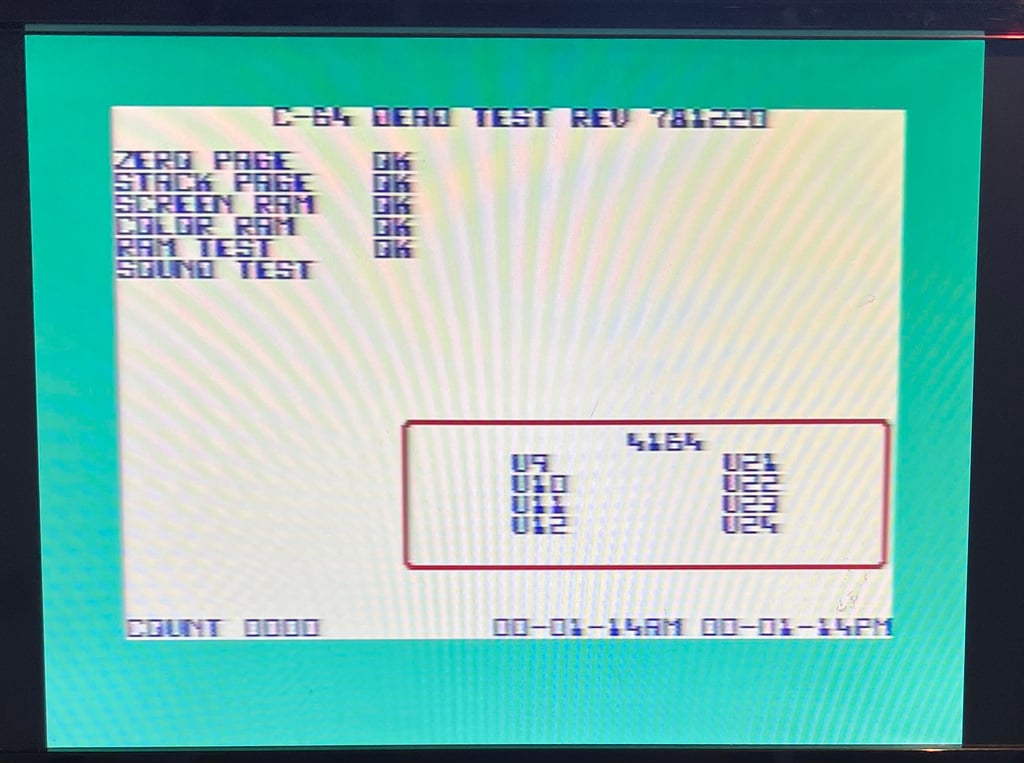
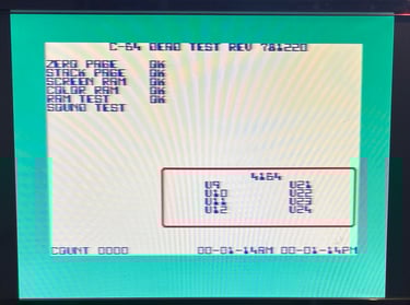
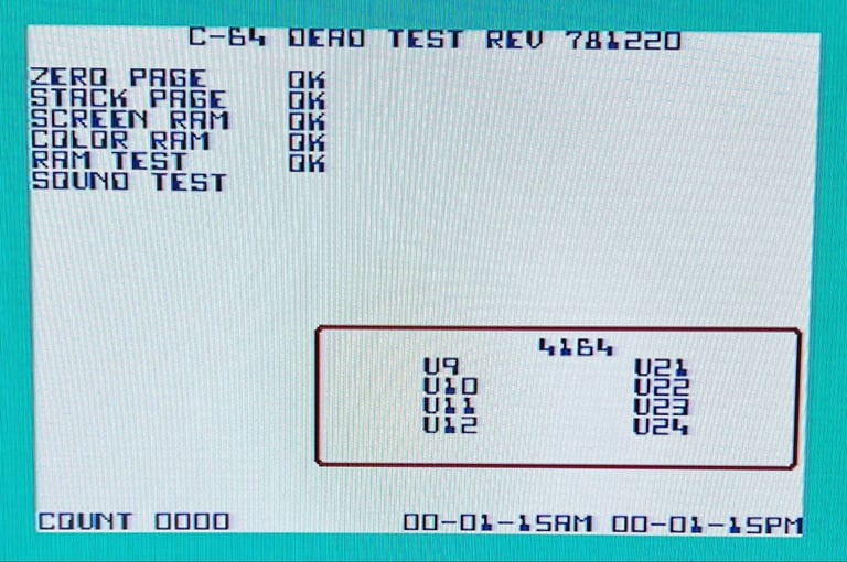
The PLA is removed which is very simple since it is socketed. And a known working PLA is used for testing. To test the machine the Dead Test Cartridge is used. And the result is:
Dead Test Cartridge boots and pass all tests (note that the SID is not installed yet)
Instead of replacing the PLA with an old PLA, which is likely to fail anyhow, a modern replacement is ordered from retroleum.co.uk: the PLAnkton-EV. This is a new "Exact Voltage" version of the popular PLAnkton module with some technical improvements such as output signal levels that more closely match original PLA chips. While waiting for the PLAnkton-EV chip to arrive from the UK a spare PLA chip is used.
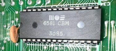
Installing the BASIC-, KERNAL- and Charset ROM + the MOS 6581 SID
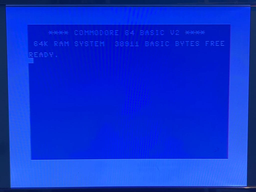
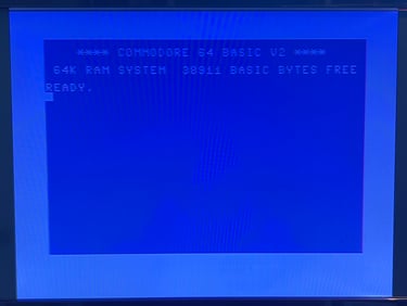
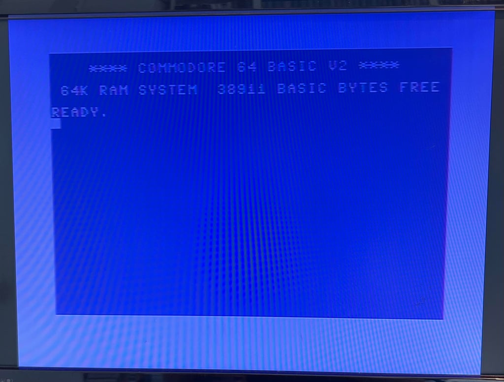
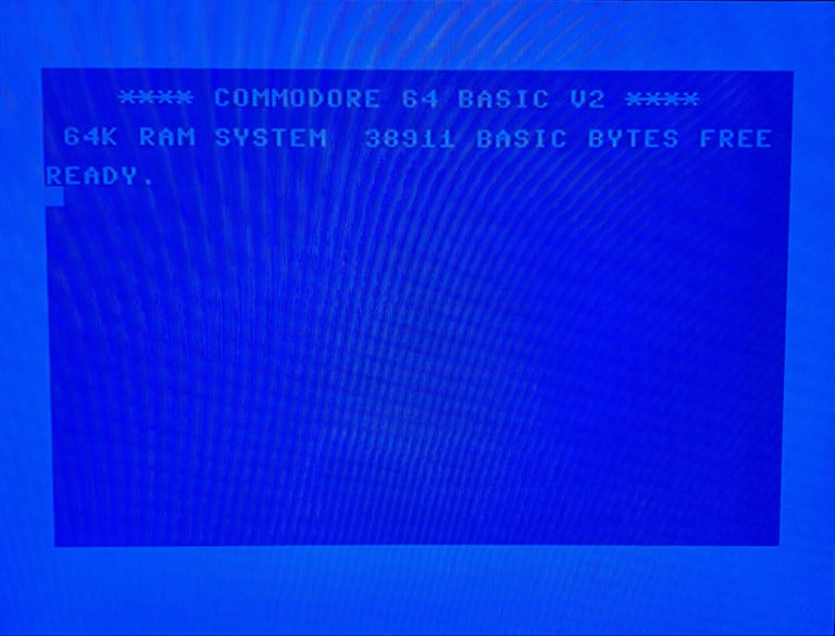
Since the machine is now running the Dead Test Cartridge software the remaining ICs are installed: The SID and the 3 x ROMS. When turning on the machine again the result is:
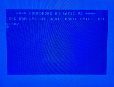
BLUE BASIC STARTUP SCREEN (38911 BASIC BYTES FREE)
A new test run with the Dead Test Cartridge the MOS 6569 SID chip is tested briefly. And it appears to be working fine.
Phew, this has been a quite expensive repair so far: 1 x VIC and 1 x PLA chip which were faulty. Hope that no other ICs is bad - but now the refurbishment can continue.
Mainboard - Refurbishment
Replacing the electrolytic capacitors - RF modulator
As with the mainboard there are electrolytic capacitors in the RF-modulator which should be replaced. But to replace the electrolytic capacitors in the RF-modulator requires the desoldering of the whole modulator container from the mainboard. Desoldering the RF-modulator is not trivial - not that it is very complicated, but it is very easy to damage either mainboard or RF-modulator if you are not careful. A detailed description on how I do this can be found in the HOWTO-article "Desolder the RF-modulator".
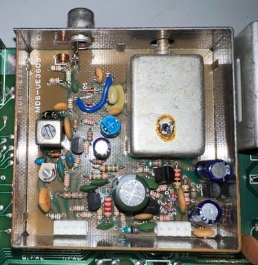
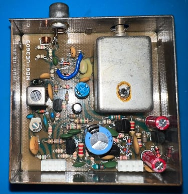
Below is a picture of the RF-modulator before desoldering. This is a RF-modulator from Mitsumi (MD6-UE3603). As can be seen from the capacitor list this RF-modulator contains four electrolytic capacitors: 1 x 10 uF [16 V], 2 x 100 uF [10 V] and 1 x 470 uF [16 V].

The RF-modulator is desoldered without any damage to traces or pads on either mainboard or RF-modulator.
All of the four electrolytic capacitors are desoldered without any damage, and four new quality capacitors are soldered back in. In the picture below the RF-modulator is shown with the new capacitors in place.

Intermesso - Another repair
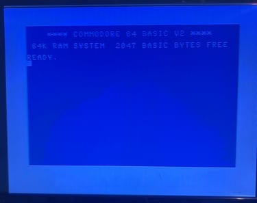
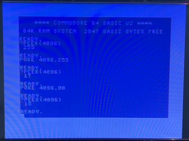
Uh oh... during (or right after) the recap of the mainboard I notice something: there are no longer 38911 BASIC BYTES FREE when the Commodore 64 boots up. Instead it only shows... eh... 2047 BASIC BYTES FREE. What have I messed up now? See picture below.

Fault hypothesis
Before trying to change any component it is good practice to try to think what could cause the fault. At first glance it might seem that this is a RAM fault, but I do not think that is necessarily the fault. Why? Well, there are some things pointing to other faults:
The number 2047 is quite special. In a kilobyte there is a total of 1024 bytes, and so in two kilobytes there are 2048 bytes. And the number 2047 is VERY close to 2048. Coincidence? Maybe, but I do not think so.
The machine is booting up and running the Kernal BASIC RAM check. If there was a real RAM fault it is more likely that the machine would not boot at all, showing error messages such as "?OUT OF MEMORY" or having stray characters such as "$", "@" etc. around the screen.
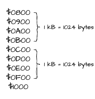
BASIC RAM is sitting between $0800-$9FFF (38911 BASIC BYTES). If the Kernal BASIC RAM check which counts the number of BASIC bytes free starts counting from $0800 there is exactly 2048 bytes between $0800-$1000. See illustration below.

Notice that the fault reading the BASIC RAM available appears to occur at exactly, or very close to (?), the $1000 address. Could the be an addressing problem instead of RAM problem? The highest nibble (four bits) of the address consists of the address lines A15, A14, A13 and A12. So my current hypothesis is that there is not a real RAM fault, but an addressing issue.
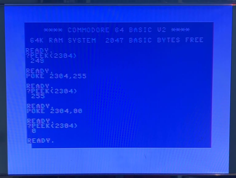
POKE and PEEK
Since the Commodore 64 is still partly operational I can use the POKE and PEEK commands to enter data at specific addresses and read them back (respectively). The plan is as follows:
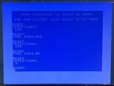
TEST #1 (Expected to pass):
PEEK the value at address $0900 to see what was registered initially
POKE in the value 255 at address $0900 to set all bits at this address. PEEK the value at address $0900 to verify that it is now set to the value 255
POKE in the value 0 at address $0900 to clear all bits at this address. PEEK the value at address $0900 to verify that is is now set to the value 0
Notice that $0900 is 2304 in decimal
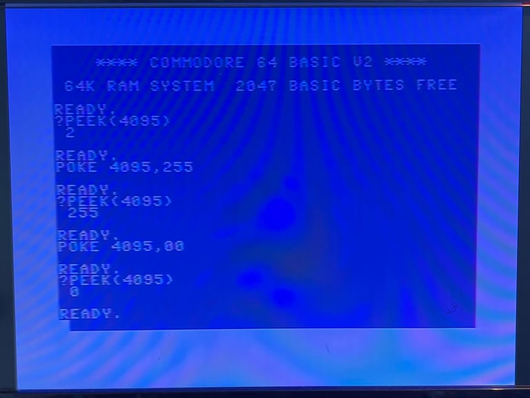
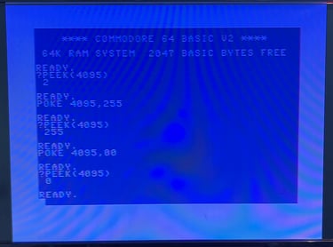
TEST #2 (Expected to pass):
PEEK the value at address $0FFF to see what was registered initially
POKE in the value 255 at address $0FFF to set all bits at this address. PEEK the value at address $0FFF to verify that it is now set to the value 255
POKE in the value 0 at address $0FFF to clear all bits at this address. PEEK the value at address $0FFF to verify that is is now set to the value 0
Notice that $0FFF is 4095 in decimal
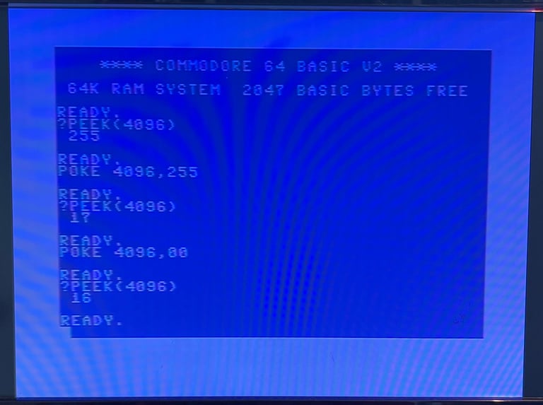
TEST #3 (Expected to fail):
PEEK the value at address $1000 to see what was registered initially
POKE in the value 255 at address $1000 to set all bits at this address. PEEK the value at address $1000 to verify that it is now set to the value 255
POKE in the value 0 at address $1000 to clear all bits at this address. PEEK the value at address $1000 to verify that is is now set to the value 0
Notice that $1000 is 4096 in decimal
As can be seen from the pictures below this is exactly what happens. This strengthens my hypothesis that there is something wrong when then address line A12 is set at $1000. It appears that all RAM is fine from $0800 to $0FFF. See pictures below.
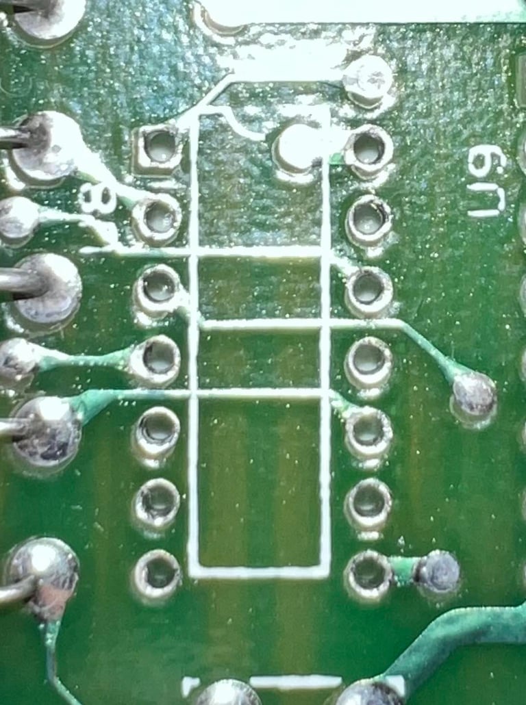
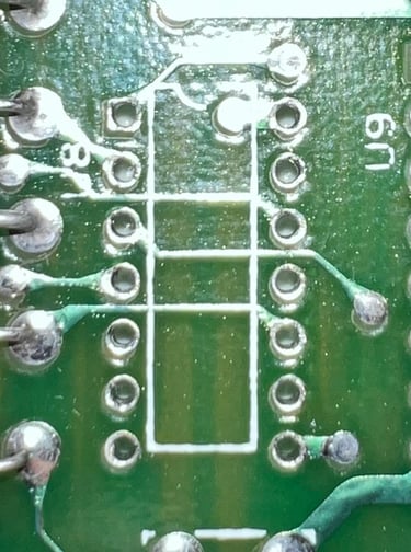
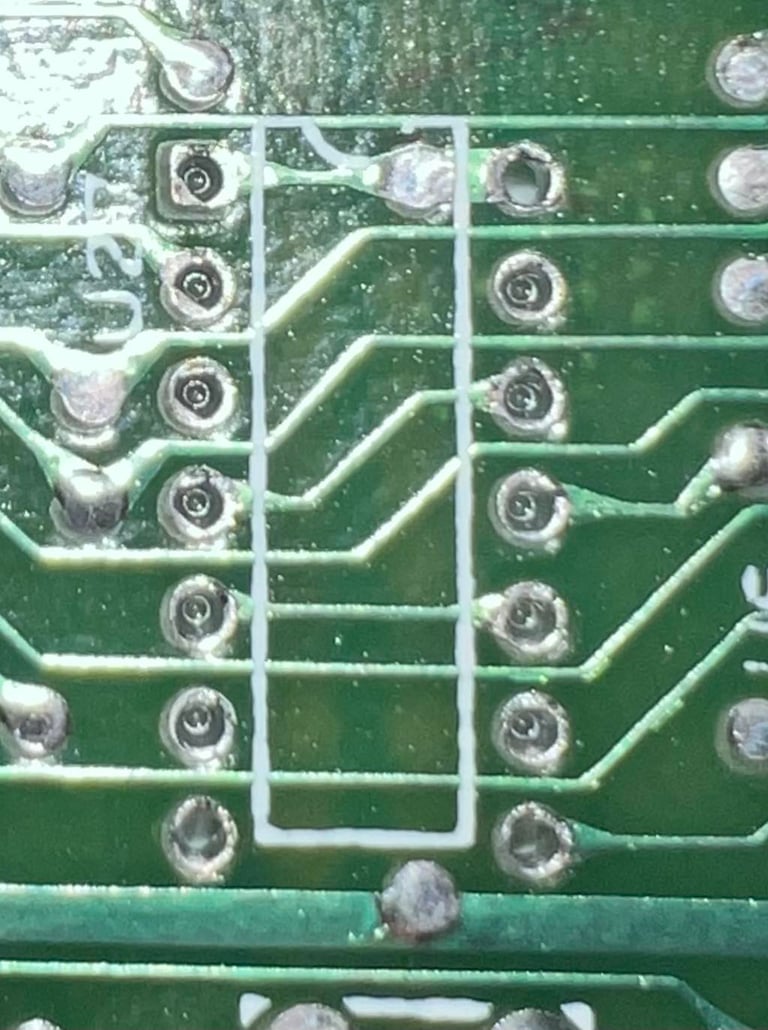
Replacing the MOS 77xx ICs
Both the MOS 7707 at U8 (equivalent with 7406) and MOS 7712 at U27 (equivalent with 74LS08) are involved in RAM circuitry. Even though I do not see any immediate reason why these being faulty should cause this kind of error I still choose to replace them with modern components. These are to be replaced anyway. Both ICs are desoldered without any damage to traces or pads. And sockets are installed. Below are some pictures from the desoldering.
This was a shot in the dark, and it turns out that this does not fix the problem. Still 2047 BASIC bytes free. So the investigation continues...
Checking the 74LS257s
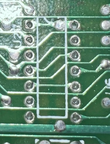
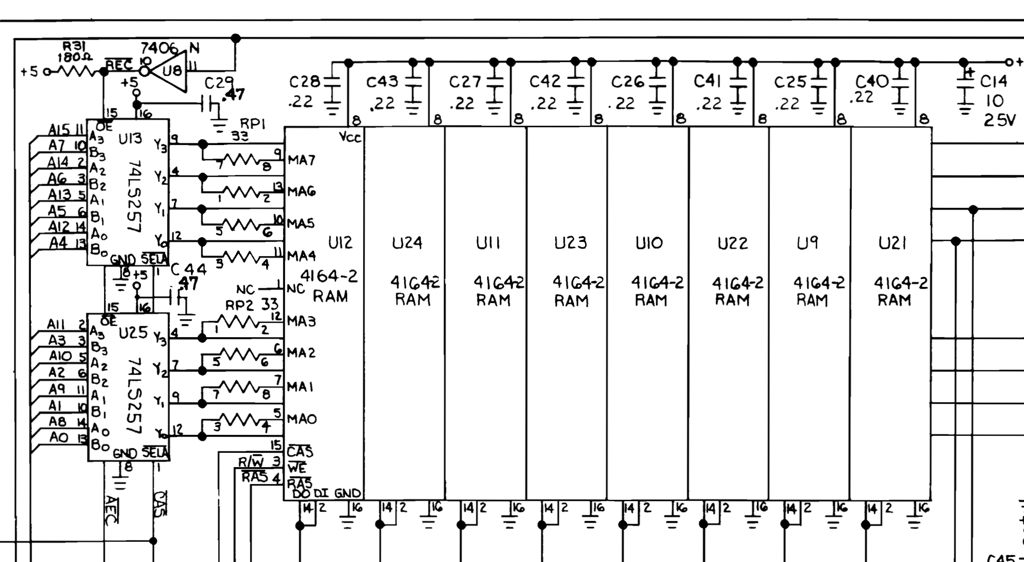
The Commodore 64 uses two 74LS257 multiplexers to address the 16 address lines to the 8 RAM chips. See schematics below. I am thinking that if any of these are faulty that this might cause the error - somehow connected to address line A12 (?).
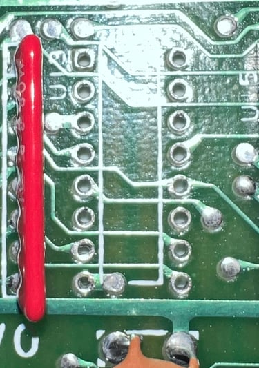
Both multiplexers at U13 and U25 are desoldered without any damage to traces or pads. New sockets are installed.

The result is still... the... same... 2047 BASIC bytes free.
Some more POKE and PEEK
Can it be that some of RAM chips are in fact bad? Sure, it can, but I still think there is something else causing this. To investigate further I make a simple BASIC program which checks the RAM cells at different address boundaries. The result of this test is shown in the table below.
The BASIC program is incredible simple, but effective. It PEEKs the value at a defined address and print the value on the screen. And with a simple loop it does this until RUN-STOP is pressed. For addresses marked as "NOT OK" the value read at the address changes continuously. For addresses marked at "OK" the value read at the address is fixed.
The BASIC program is very simple:
10 PRINT PEEK(4096) : REM $1000
20 GOTO 10
Below are two sample videos. One showing the PEEK at address $1000 which gives "random" values, and one showing the PEEK at address $0FFF which gives a fixed value.


So what could be causing this issue? Apparently as can be seen from the table above the "OK" and "NOT OK" are toggled every 8k of RAM block. This strengthens the theory even more that there is a RAM fault. Could it be that one of the address lines are stuck low or high? For example A13 which is the address line for the 8192 byte blocks?
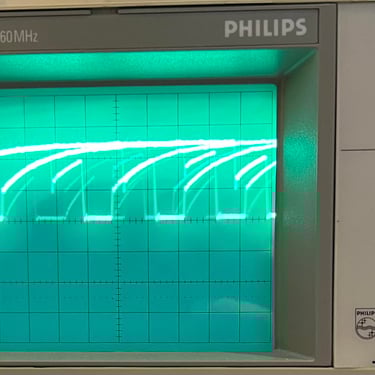
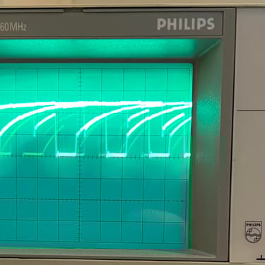
Using the oscilloscope the address lines A12, A13, A14 and A15 are checked on the PLA chip on pin #27, #2, #3 and #4 respectively. Below is a gallery of the signals measured on these lines (A12 to the far left and A15 to the far right). But as these pictures show A13, nor any of the lines, are not stuck either low or high. Instead all lines show normal activity so this does not seem to be the problem (PLA reference signals can be checked here).
Who you gonna call? Ghostbusters! Commodore 8-Bit Repair and Upgrades!
When in trouble - seek help! I am a bit stuck now. I can of course start desoldering chips, but before I do that I seek some help. Using the Commodore enthusiasts Facebook page "Commodore 8-Bit Repair and Upgrades" I ask for advice. And after just a few minutes I get the first advices all saying the same: Check the PLA! Uh oh... could it be that I have in fact destroyed my test-purpose PLA?
Installing the new replacement PLA
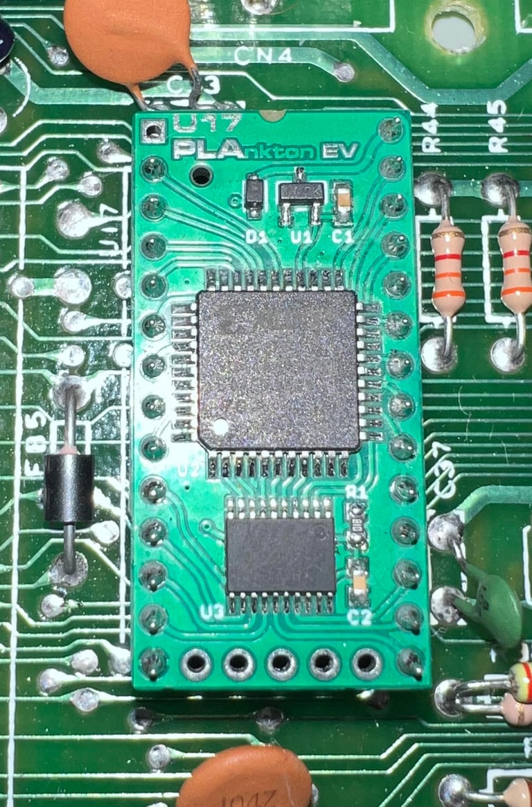
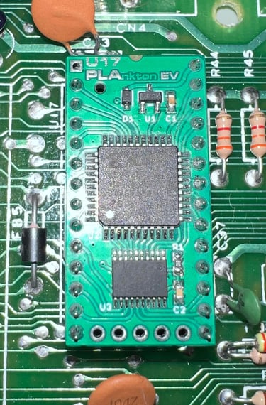
The new replacement PLA, the PLAnkton EV (Exact Voltage), is installed in the machine.
With the new PLA in place the machine is powered on, but now something new happens. The result when powering on:
BLUE STARTUP SCREEN WITH 38911 BASIC BYTES FREE - WHEN PUSHING THE CHIP DOWN
Oh... my... so it seems like there is a non-working connection somewhere. Must keep pushing forward!
Replacing the PLA socket and re-soldering IC solder points
There is obviously a bad connection or short circuit somewhere. First the IC socket in position U17 (PLA) is replaced. No traces or pads were lifted during the operation.

A new socket is installed and the machine is tested again. The result is still the same unfortunately: as long as the PLA (or surrounding ICs) are pushed down the machine works. NOTE: during the re-insertion of the PLAnkton IC PIN #14 were bent. This was fixed by replacing a new pin header.
Next action is to re-solder all the solderpoints on the CPU and 74LS373 (U26). But even with the solder points re-soldered the problem is still the same.
After quite a lot of checking / pressing the situation stabilises back to 2047 BASIC BYTES FREE. Even though the problem is not gone it somewhat helps as it fault is permanent now and not intermittent.
Desoldering the MOS 6510 CPU (U7)
A bit shot in the dark, but the MOS 6510 CPU (U7) is desoldered and a socket is installed. No traces or pads were lifted during the desoldering process.

The machine is tested with a know working MOS 6510 CPU, but the result is still the same. The fault is still there.
Cleaning the power connector / "massaging" the power switch
Prior to the task of cleaning power connector I notice something interesting: if I insert a game cartridge (not ultimax cartridges such as Dead Test) the work perfectly. The games starts and functions completely as expected. This makes me think if the "2047 BASIC BYTES FREE" is a false alarm? Could it be that the problem is caused by some timing issue due? If the power levels are not reached within the correct time - when the Kernal is doing the RAM check - that this cause a failure? I know that this sounds a bit special, but maybe...
Ok, now things are happening. While the machine is disconnected from power the power connector is sprayed with plenty of contact cleaner. And inserting/removing the power plug several times (50+) with the aim of removing any oxidation. Also, the power switch is toggled on/off (with the power disconnected) several times. When the machine is powered on now a familiar blue screen appears:

Even if this is a very good screen to see now, I do not say it is a completely success yet. I need to build confidence that this was in fact a power issue. To do that I will continue with the refurbishment and leave the machine for a few weeks to check if it still works. Could it be a bad capacitor?
Mainboard - Refurbishment continued
Replacing the electrolytic capacitors - mainboard
There are 18 electrolytic capacitors on the assy 250407 artwork 251137 Rev B mainboard according to the capacitor list. After 40 years of age electrolytic capacitors can dry out and when they do the capacitance of the capacitors change. There are different opinions on whether it is required to change the capacitors or not, but I think it is good practice to do so. And also, could the power issue (?) / RAM issue somehow be related to bad capacitors?
The 18 electrolytic capacitors are all replaced with new modern capacitors. Below is a picture of the mainboard after all the electrolytic capacitors are replaced.
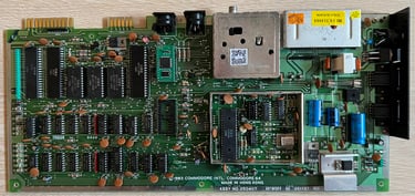
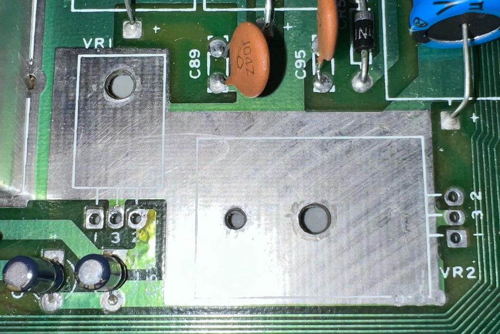
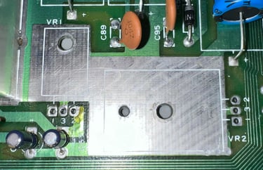
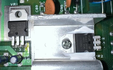
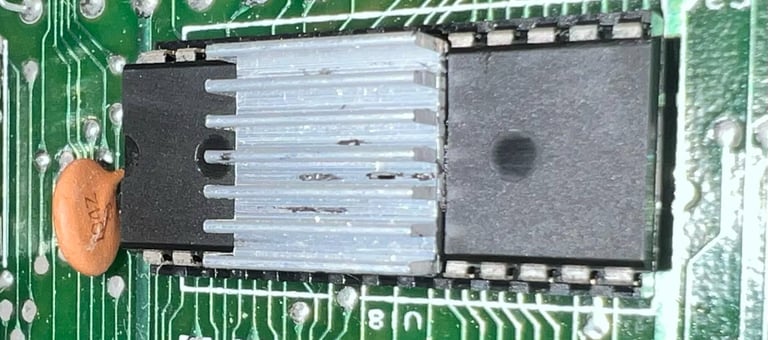
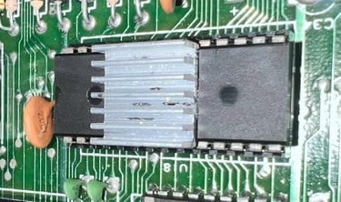
Replacing the 78xx voltage regulators (VR1 and VR2)
There are two internal voltage regulators on the Commodore 64 breadbin mainboard: a 7805 and a 7812 which produce 5VDC and 12VDC respectively. Notice that the 5VDC is not the same as the 5VDC from the power supply. The 5VDC produced local on the mainboard is used to source the VIC-II and the clock circuit, and the 12VDC is used to source the VIC-II, SID and audio amplifier circuit. A detailed description on how the voltages are produced, and used, can be found in the HOWTO article Checking the Commodore 64 voltages.
It is good practice to replace these old 78xx voltage regulators. They are 40 years old and they run very hot. If they fail they can produce an overvoltage destroying the custom chips such as SID and VIC-II. The old voltage regulators are desoldered without any damage to traces or pads.
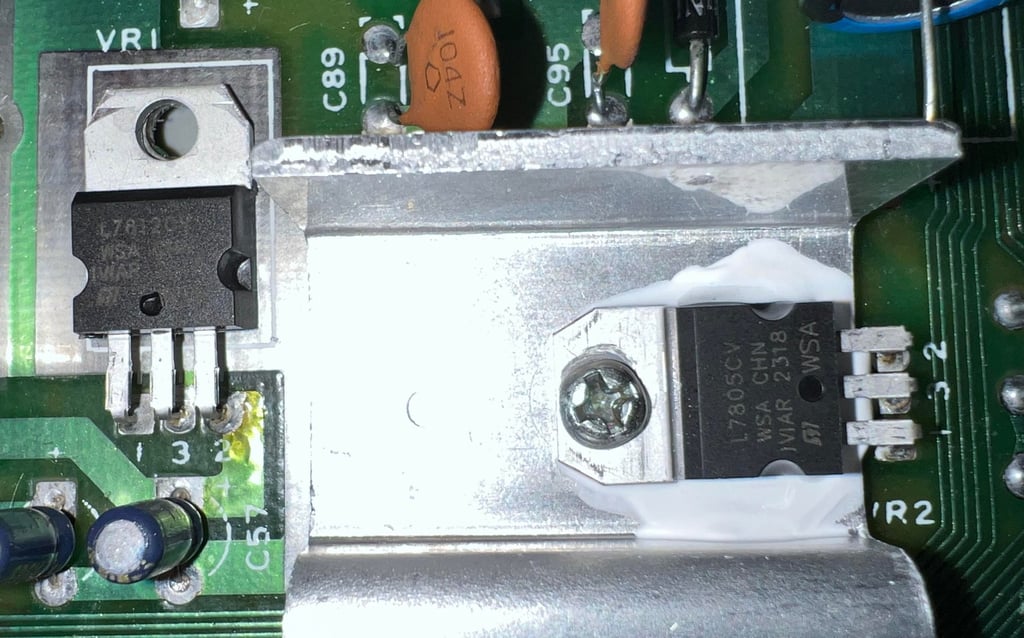
The new 7812 (VR1) and 7805 (VR2) voltage regulator are installed and soldered back in. Note that only the 7805 voltage regulator is mounted on a heat sink which is normal. A small drop of fresh heat paste is placed between the heat sink and the voltage regulator. When tightening the screw on the heat sink make sure to not tighten it too much. Since metal expands when heated it is a good idea to leave some room for expansion. Below is a picture of the new voltage regulators installed.
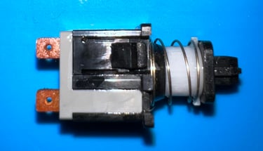
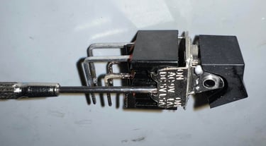
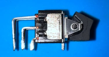
Refurbishing the power switch (SW1)
Changing the electrolytic capacitors and the voltage regulators are good practices, but it has not approved significantly on the "2047 / 38911 BASIC BYTES FREE" situation. But I still have a hypothesis that this could be related to low voltages or a too high resistance. From time to time I refurbish the power switch on the Commodore 64 mainboards. Could the "RAM" issue be related to a dirty interior of the power switch? It is definitely worth a try.
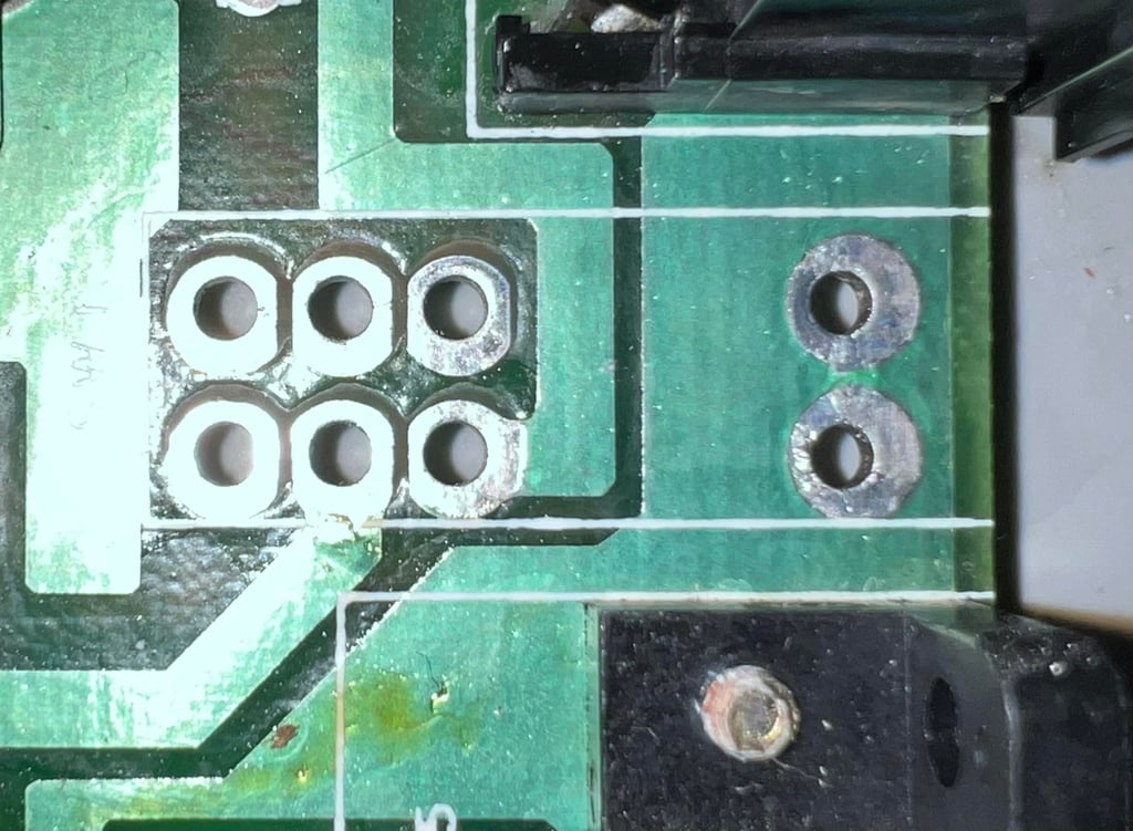
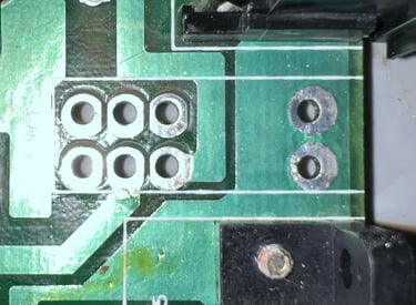
The power switch is desoldered from the mainboard without any damage to traces or pads.
The power switch is carefully pried apart and each small part is cleaned properly with isopropanol. And in fact, there is quite some grease inside this switch. Below are some pictures from the cleaning process.

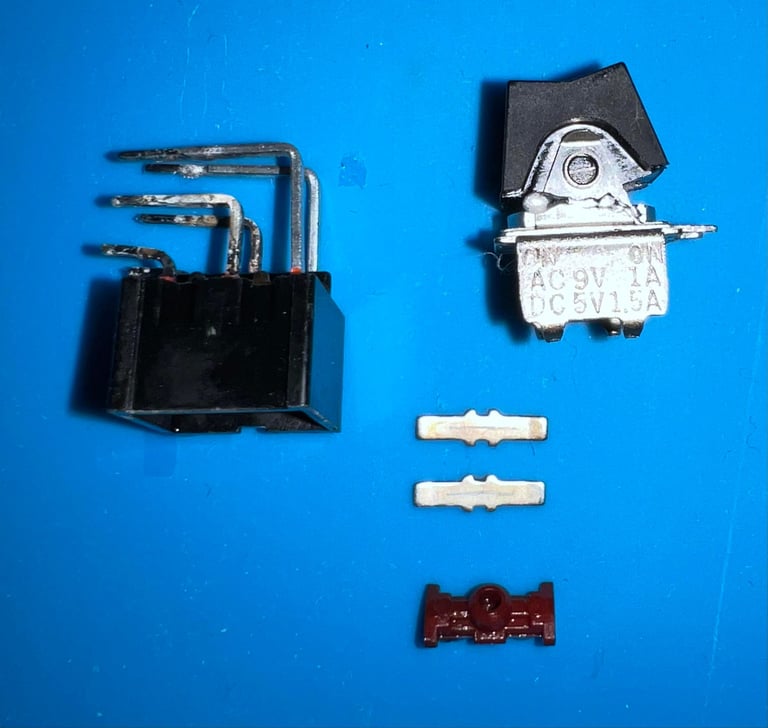

After cleaning the power switch is fully assembled again and soldered back on to the mainboard.

With the refurbished power switch in place the Commodore 64 starts to function WAY BETTER (!). In the time of writing I have not been able to reproduce the 2047 BASIC BYTES FREE issue. Could this have been the problem all the time? A dodgy power switch?! I will not declare it solved yet, but this looks very promising....
It turns out that cleaning the power switch do improve the situation - but the fault is not gone unfortunately! It is not so frequent anymore, but the fault is still there.
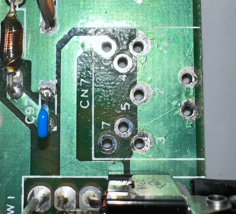
Trying to chase this fault I do two more changes to the mainboard:
Replace the power connector (CN7)
Replace the C4 and C24 electrolytic capacitors
The rationale behind this is that the power connector could be worn out and the C4 and C24 are close the RAM and 556 timer circuitry. This is a bit shot in the dark, but it is worth the try I think. Unfortunately one of the pads were lost when desoldering C24, but this is not a big deal since the pad was not connected to any trace. Below are some pictures from the operation.


These changes does not improve much on the situation. From time to time the amount of BASIC BYTES FREE differs from 38911. But I notice something else now. Instead of showing only "2047" BASIC BYTES FREE the number changes from time to time. I have tried to replace the MOS 6510 CPU earlier, but I am starting to question this again.
Replacing the MOS 67510 CPU (U7) - again
As mentioned previously I have tried to change the CPU earlier without solving the problem. But I try it once more. A known good working CPU is installed in the new socket. And now something happens... I can not reproduce the fault (yet). Could this be a case where we had in fact two faults? A low voltage and a marginal CPU?
I will test the machine regularly for a couple of weeks to see if this solves the problem. Below is a picture of the "new" MOS 6510 CPU installed.
After a few days the problem occur... again... argh.... OK! It just how these things are... I am not starting to wonder if it is actually the RAM chip(s) which are marginal. I will take a break from this machine and see if I can think of something.
Replacing the PLAnkton with original PLA (again)
I have done operation previously without success, but now I try it again. And this time it behave different. I currently can not provoke the fault back... But I am wondering if there is something between the communication between the PLA and the RAM chips which can happen, and happens more frequently with the PLAnkton installed? The suggestion to check the PLA was also the strong advice I got from the Commodore 64 repair community.
I will leave the machine for a few weeks while powering it on about every day to check if the fault re-occur.
Several weeks later... and the machine still shows the same errors! The amount of BASIC BYTES FREE varies from 2047 to 38911...
What is happening? Can this be fixed?
Ok, so I need to take a step back to think now. Chasing down this fault was harder than I first thought it would be. Before I present a possible cause for this fault (which may also be wrong), this is the current situation:
The fault is intermittent. Sometimes the machine boots perfectly with 38911 kB of BASIC BYTES FREE. When the machine does not boot perfectly is shows most of the time the value "2047", but other times what appears like completely random numbers (but they probably are not).
When the machine is reset, or powered off/on, it sometimes looks like it is "warming up". The number of BASIC BYTES FREE increases from 2047 to 38911 on each reset or power off/on.
I can not see any clear indication that neither a cold or warm machine makes any different. Whether or not i boots properly seems random.
I can not see any clear indication that bending the board makes any different. This could be the case if there was a bad solder joint, but I see no traces of this. Pushing down the ICs does not show any difference either.
Running games from cartridge seems to work fine. Whether this is a fluke (used at times the machine would boot ok) is hard to tell, but I don´t think so.
Every single time I run the Dead Test Cartridge all tests pass. No signs of any RAM fault at all.
Faults hypothesis #1
I don´t think that the 4164 RAM ICs are faulty. It could be tempting to just start replacing one-by-one RAM chip, but I think that is a wild goose chase. Instead, I think the fault is caused by noise. Not in the traditional way like electromagnetic disturbance, but noise on the databus. Like several ICs trying to push data on the databus at the same time.
The reason why I think this could be the problem is based on:
When the machine boots to "2047 BASIC BYTES FREE" blocks of 8 kB of RAM are OK/NOT OK alternately
When peeking the faulty memory location the data read back appears to be "random". The data read back changes for each peek.
Every single time I run the Dead Test Cartridge all tests pass
So, what if the ROM chips (or some other chips) are presenting the signals on the databus at the same time as the RAM chips? Just like people talk into each other´s mouth.
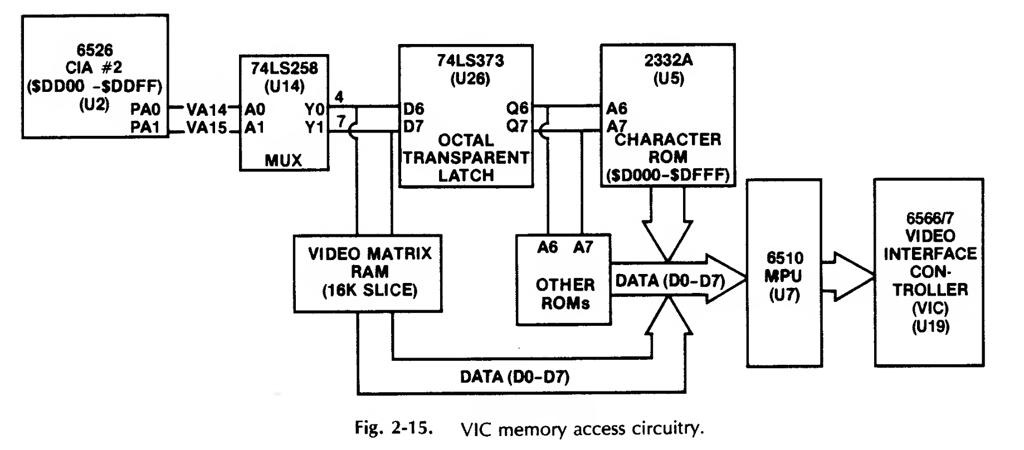
The schematics below is taken from another context (seen from a VIC-II perspective), but notice how a 74LS258 (U14) is used as a multiplexer to enable the Character ROM and "Other ROMS" to send data to the databus. My hypothesis is that there is something faulty around this multiplexer... Either the ICs itself, or maybe CIA#2 or... something else related.

Faults hypothesis #2
It has been almost six months since I last worked on this machine. And during these months something has happened:
I can no longer re-produce the memory fault
I have abandoned the old C128 power supply, and now use a modern replacement
So, was it that simple all the time? A power supply with just a little low output? I do find it a bit hard to believe (or maybe admit to myself) that it is that simple.
To see if this solves the memory issue I plan to do the following - with the aim of trying to provoke the memory fault to reoccur:
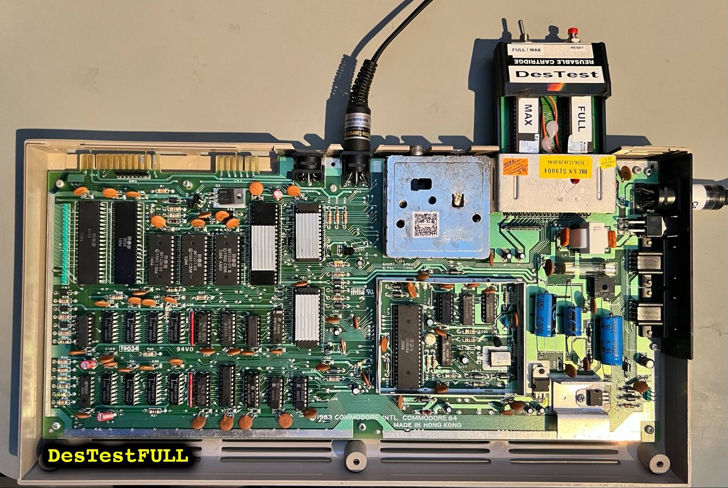
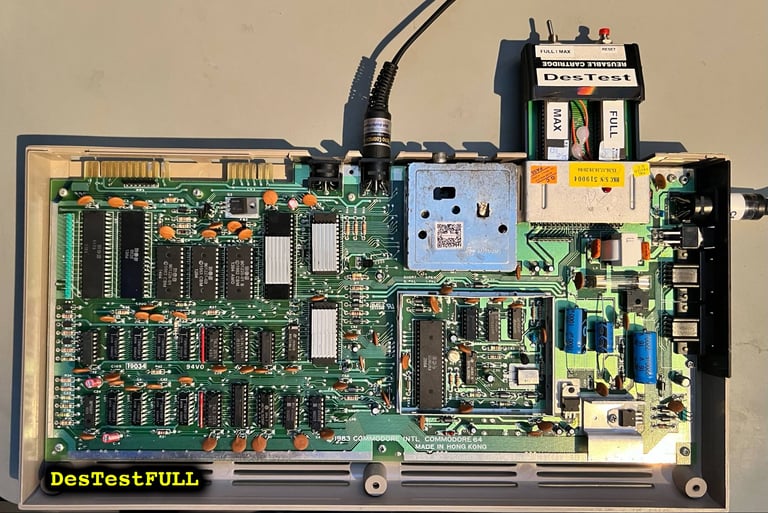
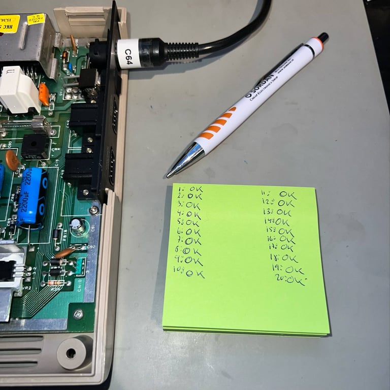
Power cycle the machine 20 times (with a 15 seconds interval) to see if the 38911 BASIC BYTES are shown every time
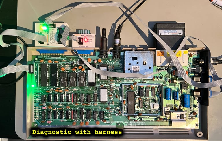
Run the full diagnostics with harness. This will test not only the first 4 k of RAM, but the whole memory range
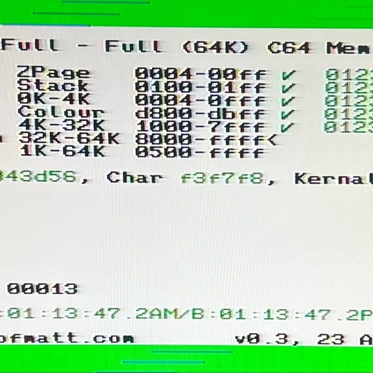
Run the DesTestFull test for 60 minutes. The DesTestFull will test the whole memory range with the sophisticated March-B algorithm.
I can not see any faults at all no more. All tests pass with flying colours. Below are some pictures from the testing process.

Wrapping it all up
During the testing an interim RESET-button is soldered to the USER PORT. This leaves two of the pads with some solder, but the user port will work just as good. Also, some heat paste is added to the VIC-II and the combined RF-shield and heatsink is attached.
Finally, the voltages are measured (now with the new modern power supply).
Can I say with 100 % certainty that the power supply was the cause of the mysterious fault? No. But with the new modern power supply in place, I am not able to reproduce the problem so I can´t do much else than belive this was the culprit.
Now the machine will be fully tested (again) in the last chapter. If I can´t find any issues with it here, I will declare the repair a success.
Testing
Proof is in the pudding - does it work?
Testing is done through three main stages:
Testing the basic functionality and chips
Testing the complete set of custom ICs and I/O ports
Testing by using the machine playing demos, games etc. accessed by both floppy and datasette to verify correct operation
Basic functionality and chips
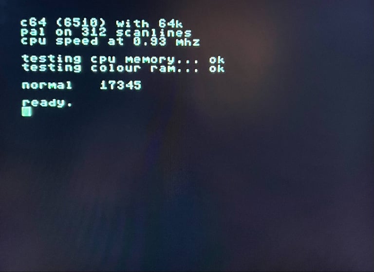
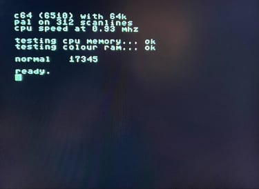
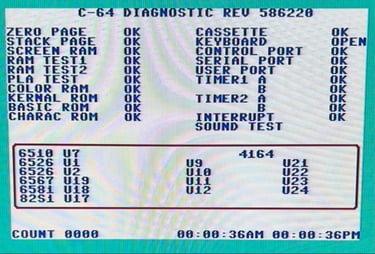
First test is done using the Dead Test Cartridge. This test doesn´t test all the functionality of the Commodore 64, but it does test the basic functionality of the major chips such as the CIA #1/2, CPU, VIC-II, PLA, RAM and SID. As the picture shows below the test is passed.
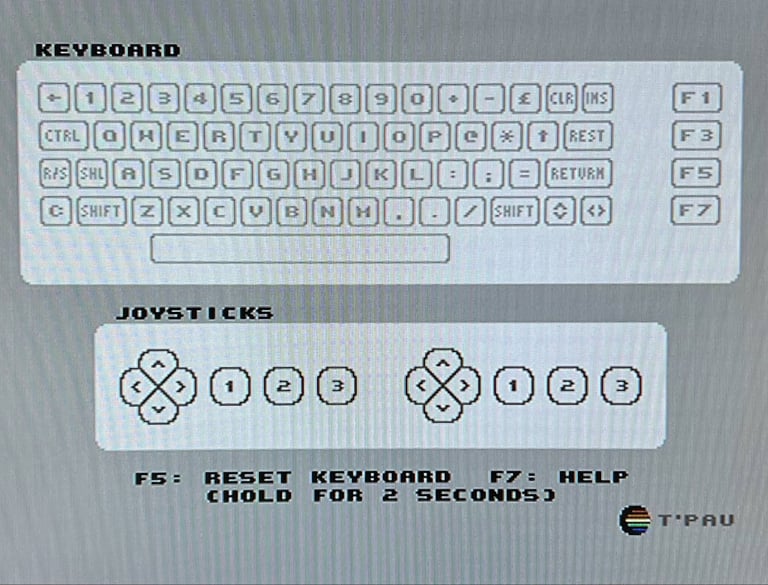
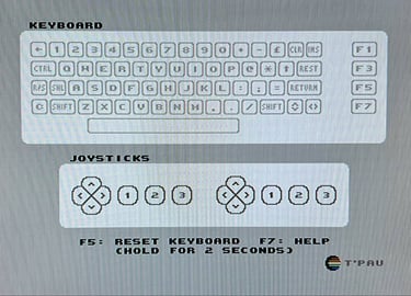
Next test is to power the Commodore 64 to the blue boot up screen and also check the keyboard to make sure all keys works as they should. The test is passed; all keys works and 38911 BASIC Bytes Free.
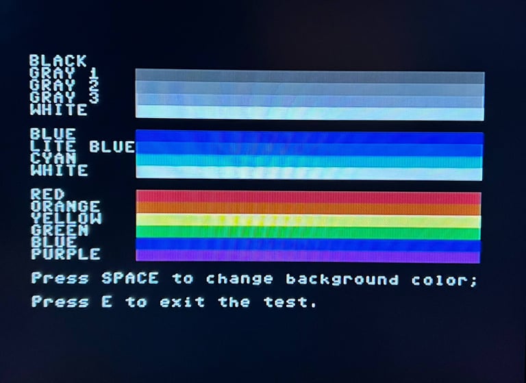
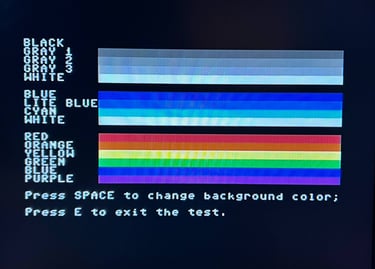
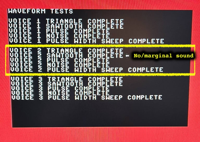
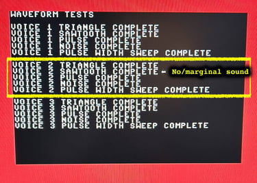
The basic functions of the VIC-II, SID and RAM is tested with 64 Doctor, Commodore 64 SID tester and MemTest64. Note that this is to be considered as basic functionality - more advanced (?) functionality such as sprite handling / collision detection / advanced audio will be tested later. Here something happens. The basic tests pass for the memory and video without any detected faults. But for the audio tests I notice that there is something wrong Voice #2 in combination with the SAWTOOTH pulse.
The interesting thing is that I have not noticed anything wrong before using the diagnostics tools. All of these pass (as far as I can hear), but there is obviously something marginal with this 6581 SID chip. So this has to be changed in my opinion. Even though it is very annoying to have a marginal SID (these are expensive), it is good to see that the testing process works identifying faulty/marginal chips.
Replacing the SID
You could argue that the SID is not broken since it is really hard to detect it. But I do think it is important to try to get the most of these Commodore 64 machines - and that includes a fully working SID. To accomplish that a working MOS SID is transferred from another Commodore 64. This SID is slightly younger (from 1985 compared to 1984).
The machine is tested again with the new SID an everything tests fine. Nice! Below is a picture of the new SID in place.

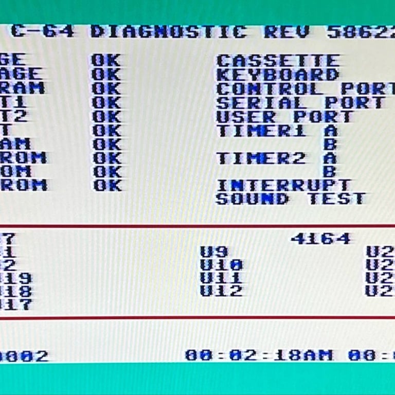
Diagnostics test with harness
To test all the custom ICs, and I/O ports, the Diagnostics cartridge is used. The Diagnostics cartridge is very valuable when the complete test harness i installed as in "everything" is tested formally. As can be seen from the picture below, no issues are identified.

Extended testing
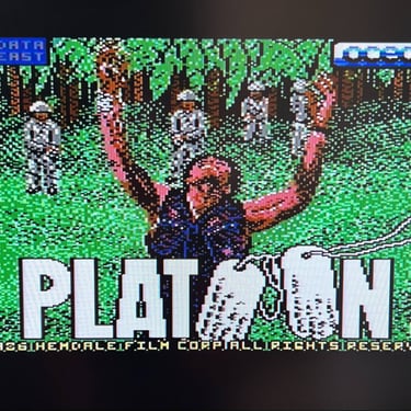
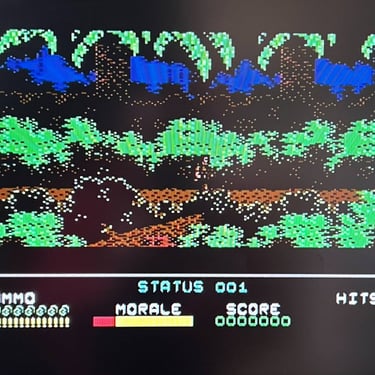
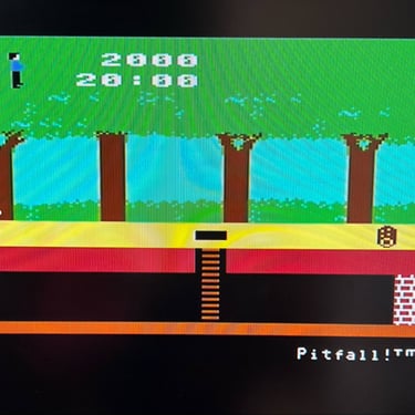
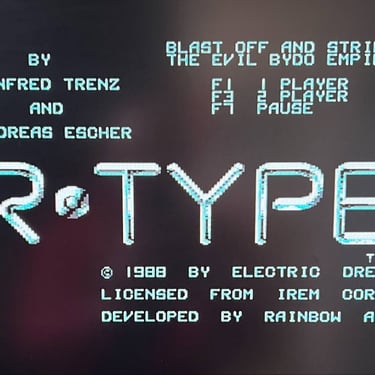
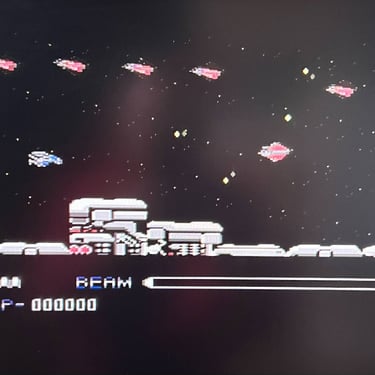
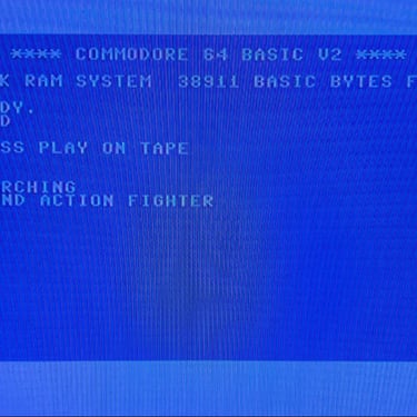
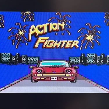
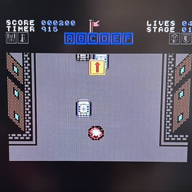
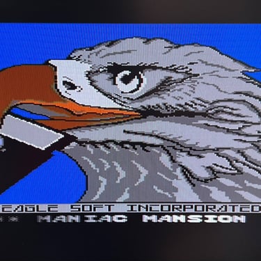
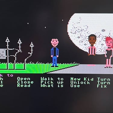
Knowing that the basic functionality of the machine works I continue the testing by using the Commodore 64 for normal operations; playing some games, watching demos, loading from datasette and floppy and using a cartridge. I can not find any issues with this machine. I also pay special attention to the video to make sure that there are no glitches in the graphics - I can´t see any abnormalities. Below is a gallery with pictures from the testing.


Final result
"A picture worth a thousand words"
Below is a collection of the final result from the refurbishment of this C64. Hope you like it! Click to enlarge!

Banner picture credits: Evan-Amos