
MeGALoDOS
V1.42F
For Commdore 1541-II
Project scope and plan
It´s a bird... It´s a plane... It´s MeGALoDOS!
Background
Recently I saw for the first time a 1541 floppy drive running DolphinDOS 2.0 fand I was flabbergasted. Why? The speed when loading both directories and files were incredible fast compared to normal fast loaders. Maybe I have been living under a rock for the last 40+ years, but I would not be too surprised if also others have missed the magnificent speed a normal-looking 1541 floppy drive could provide.
How could a 1541 become so incredible fast? Normally, the 1541 floppy drive is connected to the Commodore 64 via the SERIAL PORT. Somewhat faster loading over the SERIAL PORT can be achieved by replacing the original Commodore Kernal/ROM DOS routines with optimised versions (e.g. JiffyDOS and cartridge fastloader). But if you want to see really high transfer speeds the 1541 floppy drive will utilize the USER PORT (aka the parallell port). Now the 1541 floppy drive will be FAST!
Solutions such as DolhpinDOS, Professional DOS and Prologic DOS are examples of 1541-speeders utilizing the USER PORT. Each solution differs somewhat in speed and functionality, but what they have in common is that they communicate with the C64 via the USER PORT. For such solutions it is required to modify the 1541 by installing a custom PCB enabling USER PORT communication, and in addition a custom ROM image on the Commodore 64 must be installed.
Imagine a solution that could combine all types of floppy speeders... both USER- and SERIAL PORT loaders. Well, say hello to MeGALoDOS!
MeGALoDOS is the ultimate floppy speeder hardware for the 1541 and 1541II designed by Thomas Linke. Based on a CPLD, the hardware of all common floppy speeders are replicated to be utilized in both the 1541 and 1541II floppy drives.
In addition to the original DOS on the motherboard, MeGALoDOS offers (from the MeGALoDOS assembly- and user instructions):
Professional DOS (Rapi DOS)
Dolphin DOS (2.0)
Prologic DOS
Speeddos Expert (40 tracks) and Speeddos (35 tracks)
S-JiffyDOS and JiffyDOS (licensing required!)
Turbo Access and Turbo Trans
Quick DOS
All hardware features of the original Speeder are replicated:
Track buffer RAM
2MHz mode (Professional DOS, Prologic DOS)
RAM Floppy (TurboTrans)
Using a small ATMega processor, MeGALoDOS also provides the following features:
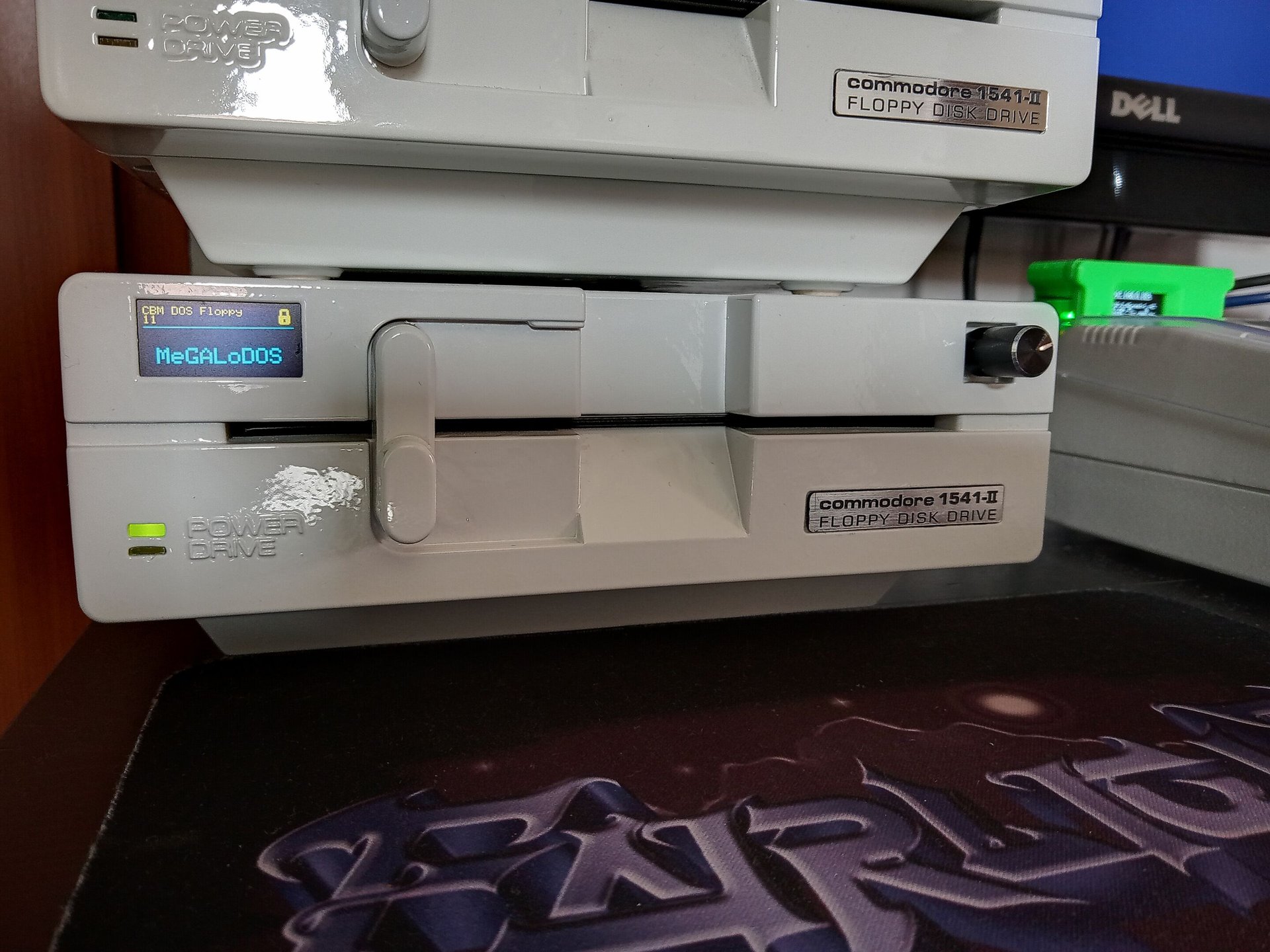
Track display
Selection of DOS via display
Electronic disk punch
Electronic write protection
Electronic setting of the device number
Reset button
Project scope
The goal is to install the MeGALoDOS in a 1541-II (Chinon) floppy drive, and to use this together with a C64G equipped with a SuperKernal ROM switcher.
Milestones
- Assemble MeGALoDOS v1.42F module
- Mount cables with DuPont connectors on the rotary switch and LED
- Assemble the VIA parallell adapter
- Mount DuPont connectors on the OLED display
- Assemble the USER PORT adapter
- Install MeGALoDOS (including all modules and parts) in 1541-II floppy drive
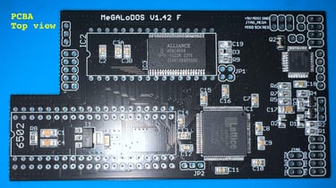
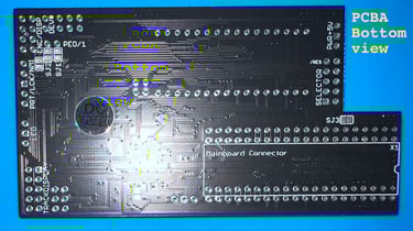
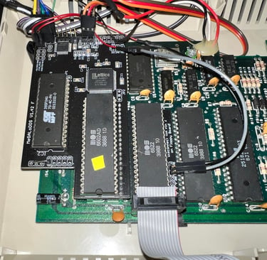
Assembly - MeGALoDOS v1.42
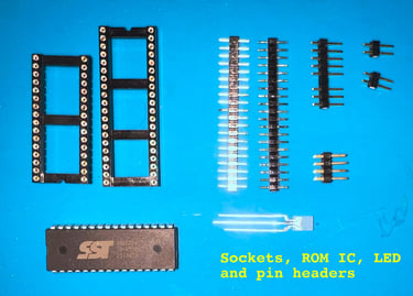
All the parts required for the MeGALoDOS v1.42F module come in an antistatic bag. The SMD components are already mounted on the PCB (phew!). What remains is to solder the IC sockets and pin headers.
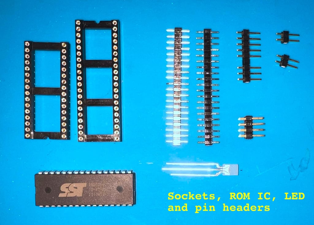
The content is:
1 x MeGALoDOS v1.42F PCBA
1 x 40 pin machined socket
1 x 32 pin machined socket
1 x 32 pin 4 Mbit Flash memory IC (SST 39SF040/70-4C-PHE)
1 x dual color LED
2 x 20 pin header strip
1 x (3+5) pin header strip (actually space for nine, but one pin deliberately removed)
1 x (2*4) pin header strip
2 x 2 pin header strip
Below are pictures of the parts listed above.


To assemble the MeGALoDOS board the instructions stated in the "MeGALoDOS assembly- and user instructions" (German) are followed. Unfortunately, I do not speak German, but I will try my best to follow it. The assembly instructions are well documented and supported with pictures. So with some luck, Google translate and helping hand from Thomas Linke I think we should be fine.
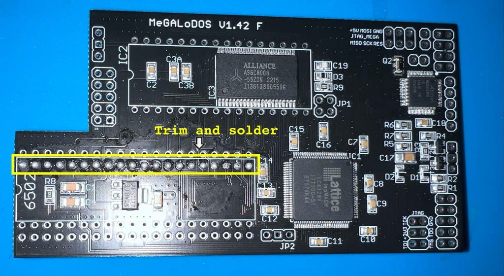
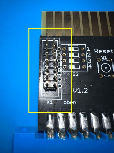
STEP#1 - Soldering the first 20-pin header
The first action is to solder one of the 20-pin headers to board. In the picture below you can see where the pin header is soldered.
NOTE#1: before soldering the 20 pins are shortened slightly. Why? To make sure that the 40-pin socket is flush to the board the pins beneath (from the 20-pin header) can not protrude too much. The pins are shortened using a diagonal cutter.
NOTE#2: take care to install the 20 pin headers in the correct place. Since there are four places where this would fit, it is nice to place this right the first time (unless you love desoldering).
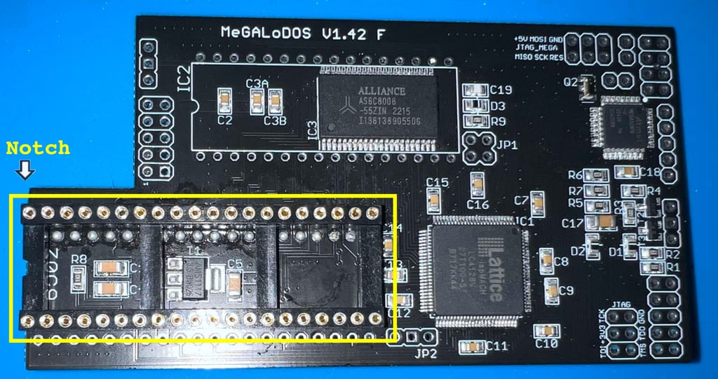
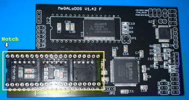
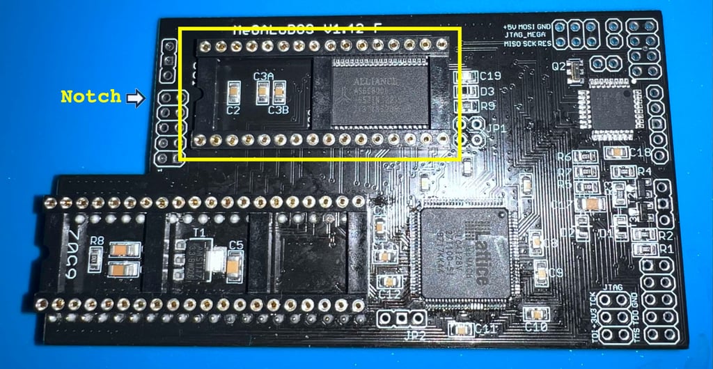
STEP#2 - Soldering the 40-pin socket (6502 CPU)
The 40 pin machined socket is soldered to the board. It is important to make sure that the socket is flush with the board. A good way to secure that is to solder only one pin in two of the corners first. While re-heating the solder points the socket is firmly pressed into the board making it flush.
NOTE: Make sure to place the socket the right direction aligning the notch (see picture below). Although it is not the end of the world if its the wrong way, it looks better and you reduce the risk of someone misplacing the 6502 CPU and damaging it.
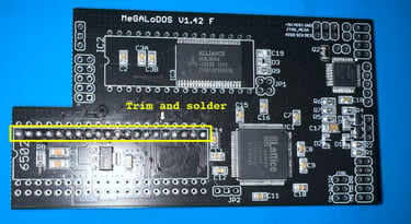
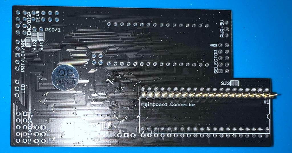
Flipping the board this is what it looks like at after step #2.

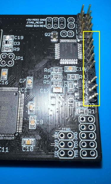
STEP#3 - Soldering the second 20-pin header
The second 20- pin header is soldered in place. There is only one row available left so the placement should be easy to find. See picture below.
STEP#4 - Soldering the 32-pin socket (Flash memory)
The 32 pin machined socket is soldered to the board. In the same was with the 40-pin socket two of the corners are soldered first. While re-heating these solder points the socket is pressed down firmly making it flush with the PCB.
NOTE: Make sure to place the socket the right direction aligning the notch (see picture below). Although it is not the end of the world if its the wrong way, it looks better and you reduce the risk of someone misplacing the Flash memory and damaging it.

STEP#5 - Soldering the (2*4) and (3+5) pin headers
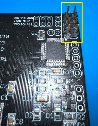
First the 2*4 pin headers are soldered into the top right corner of the board. These pin headers will connect to the rotary encoder and a SPI display later. In the picture below you can see the position of these when they are soldered in place.

Just below the (3+5) row of pin headers are soldered. This row of pin headers will connect to the floppy drive and multicolour LED later. See picture below.

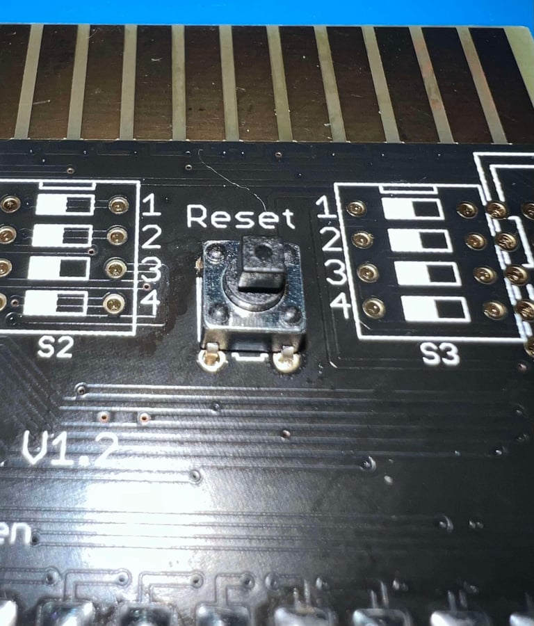
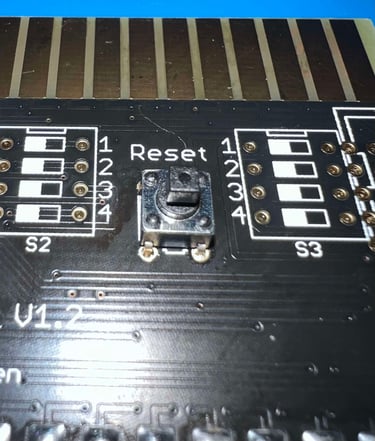
STEP#6 - Soldering the 2 pin header and a 90 degree pin header
A 2 pin header is soldered in for the DEV# connector just next to the row of (2*4) pin headers. See picture below. These pin headers will be connected to the #0 and #1 on the VIA board later.
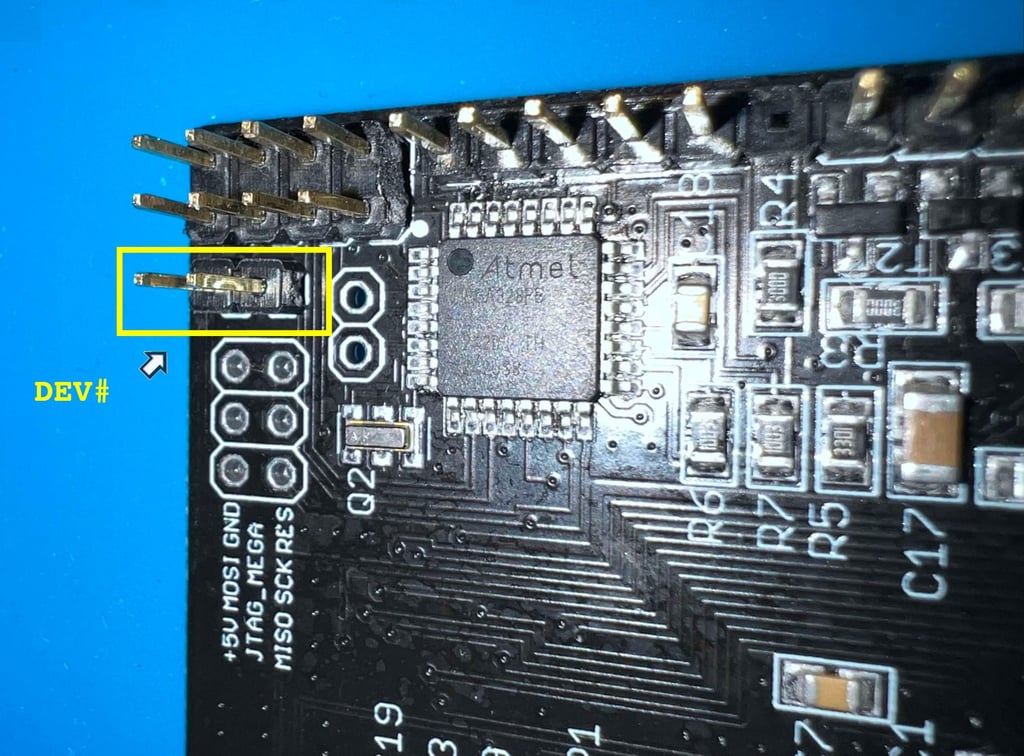

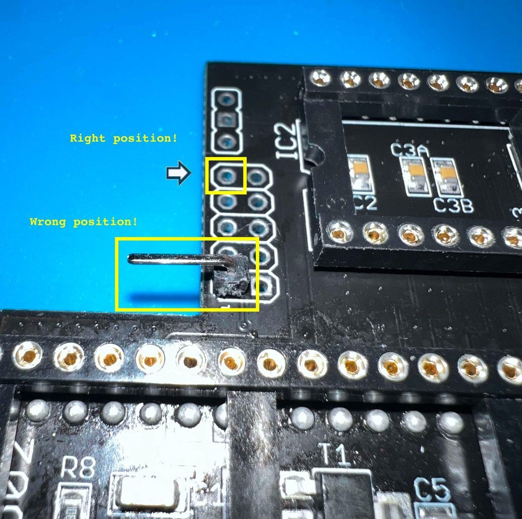
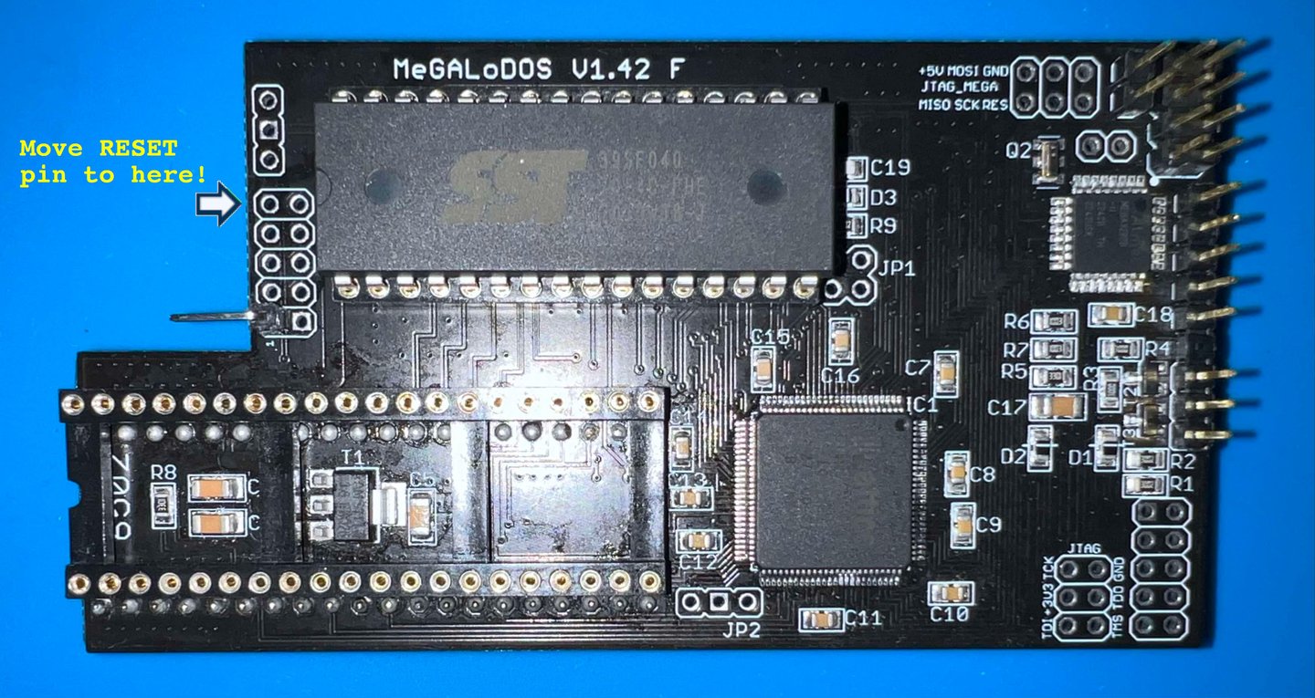
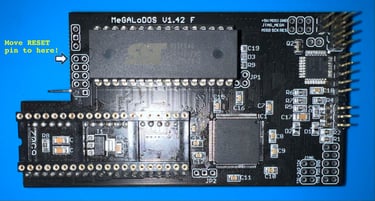
Since the MeGALoDOS is going to be installed in a 1541-II soldering a 90 degree angled pin header for the RESET line might not be required. Nevertheless, I solder in such a pin header as a precaution. See picture below. UPDATE: The RESET pin was installed in the wrong place. The original picture is still shown below, but with a text showing where the correct place should be.

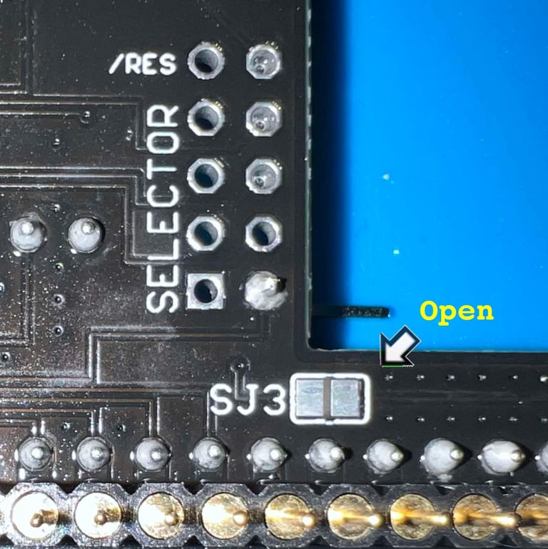
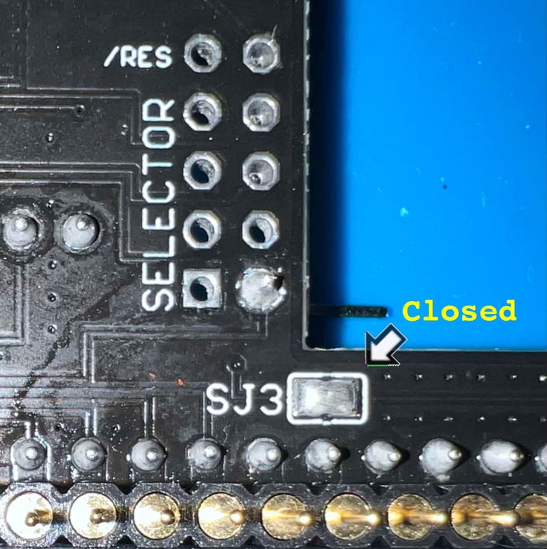
STEP#7 - Closing the jumper SJ3
As mentioned this MeGALoDOS will be installed in a 1541-II floppy drive. Therefore the jumper SJ3 should be closed on the MeGALoDOS board instead of using the RESET cable (according to the user manual there are some cases where this not function and the RESET line should be used instead). See pictures below - both before and after bridging the the SJ3 jumper.


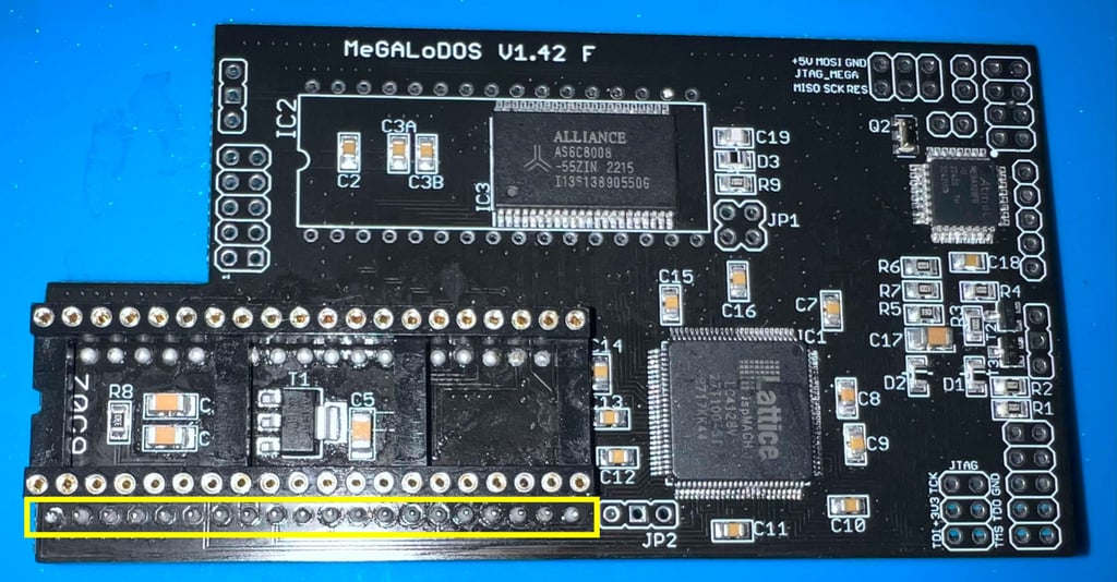
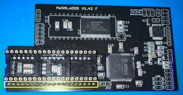
STEP#8 - Installing the flash memory
Final step is to install the 32 pin flash memory IC in the socket. The MeGALoDOS v1.42F module should now be completed, and the next assembly can start. Below are pictures of the MeGALoDOS module after assembly.

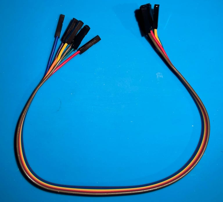
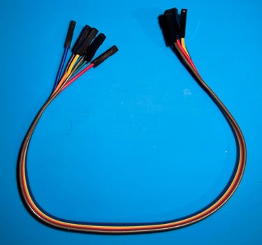
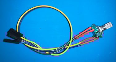
Rotary encoder and LED
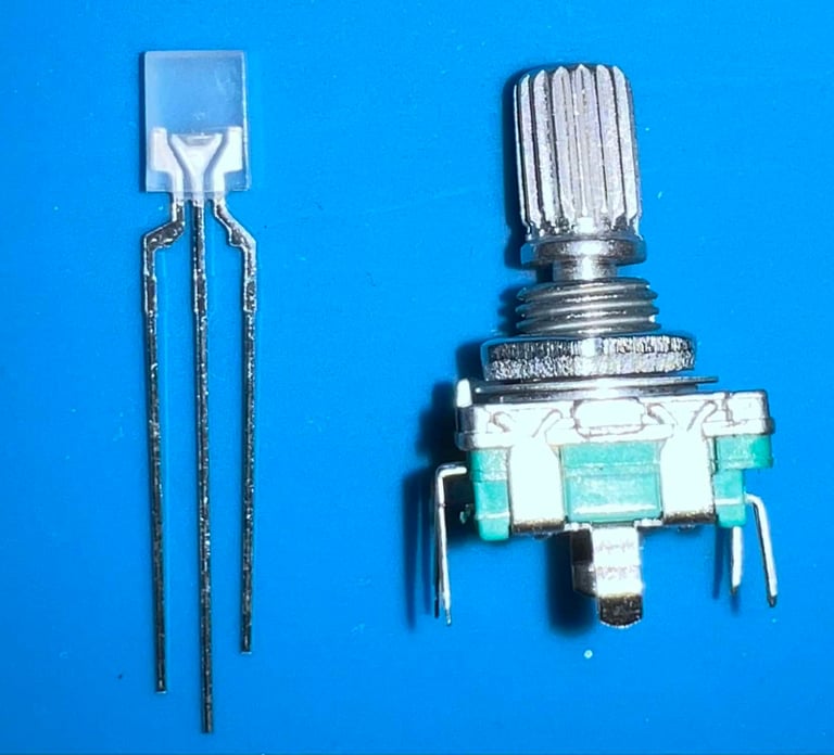
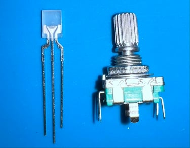
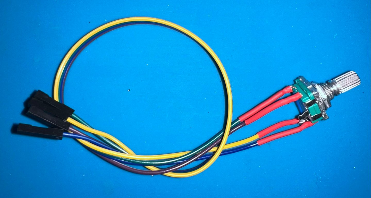
The MeGALoDOS will be equipped with display which show the current ROM Kernal in use. To choose between ROM Kernals a rotary encoder is used. In addition a dual coloured (RED/GREEN) LED is used to show status (what this status represent is I am not sure of yet - but that will be apparent later). Both the rotary switch and the LED must have cables which have female DuPont connectors. Below is a picture of the parts that will be assembled to accomplish this.
Rotary encoder
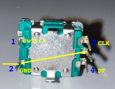
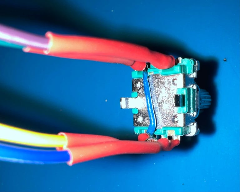
Before the four DuPont cables are connected to the rotary encoder the center pin must be soldered to another pin. Which one? In the picture below the rotary encoder is seen from below. With the row with three pins on the right hand side, the center pin must be short circuited to the bottom left pin.

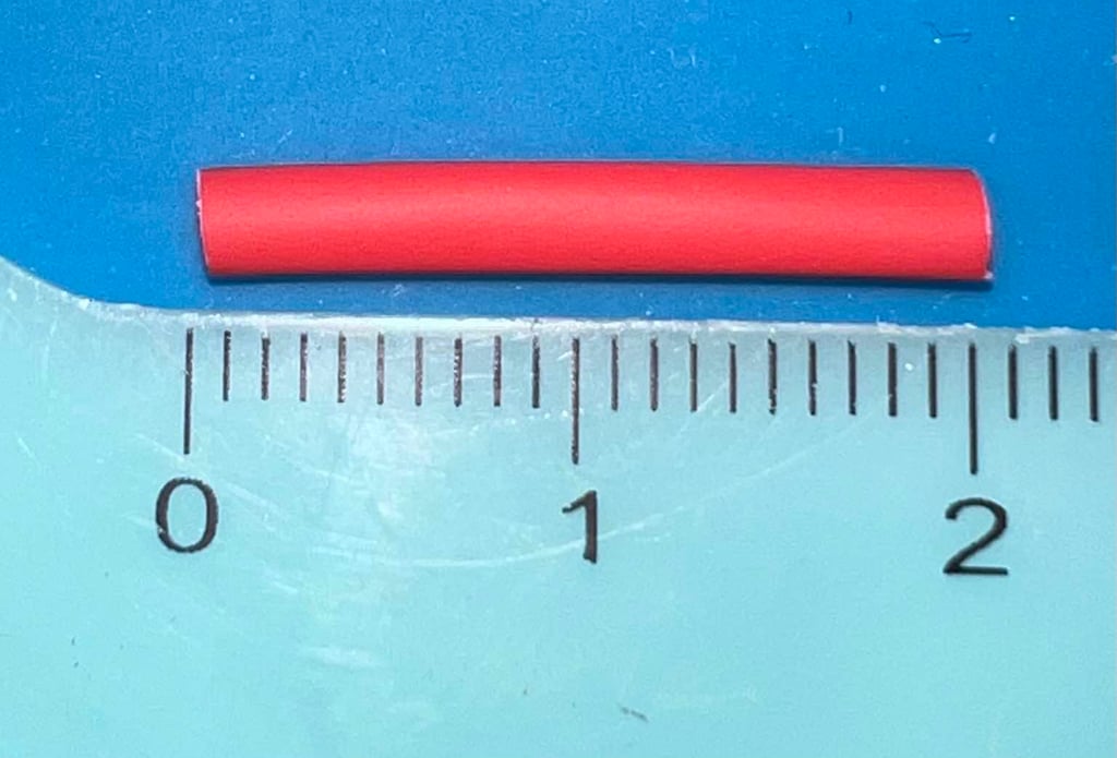
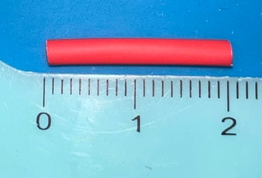
To prevent the cables from short circuit when soldered to the parts seven heat-shrink tubes will be used. Each of the tube is cut to be approximately 2 cm long.
A small insulated wire is soldered between the center pin (right side) and the bottom pin (left side). Then the remaining four DuPont cables are soldered to the position 1-4 as shown in the picture above. NOTE: the DuPont cables can be fiddly to solder on the pins as the metal is the cable is not very susceptible to the solder. But with plenty of flux and patience the cables are soldered in place.


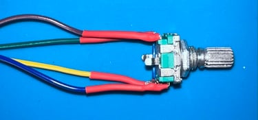
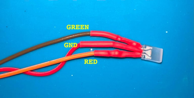
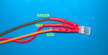
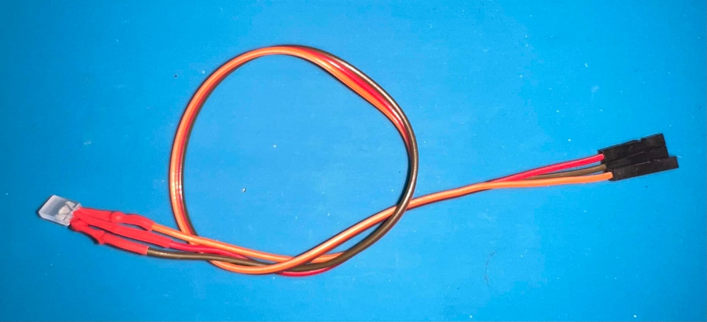
Dual coloured LED (RED/GREEN)
The dual coloured LED is soldered to three DuPont cables in the same way as the rotary switch. Heat-shrinking tubes are used in the same way.
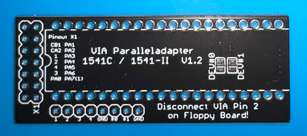
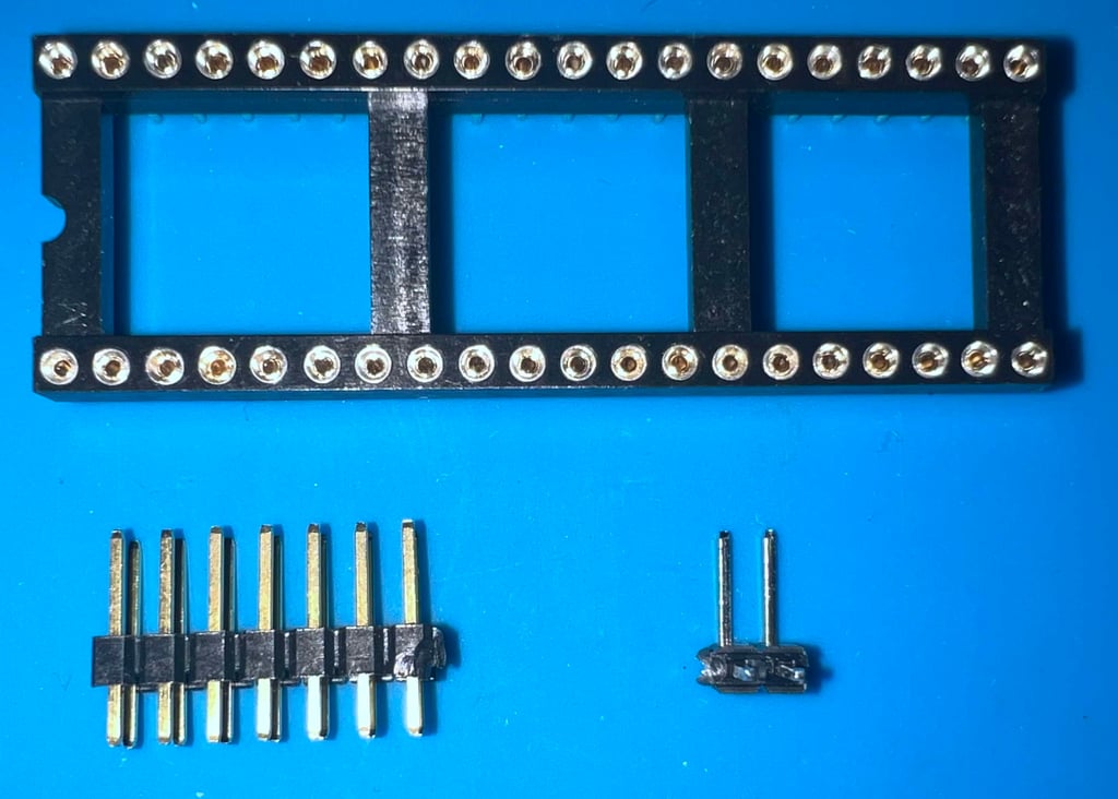
VIA parallel adapter V1.2
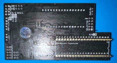
One of the VIA chips in the 1541-II floppy drive will function as a parallell interface to the Commodore 64. But do be able to do that the VIA must be installed in an adapter which allow a parallell USER PORT cable to be attached. Below is a picture of the VIA adapter before any components are soldered onto the PCB.

Only three parts will be soldered to the PCB:
40 pin socket
2 x 7 pin header
1 x 2 pin header (90 degree angle)

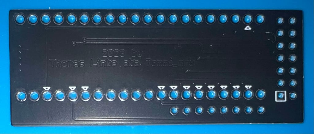
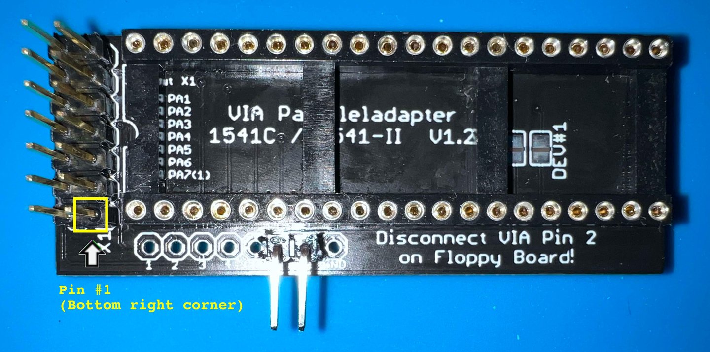
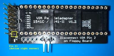
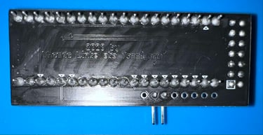
In the pictures below the VIA adapter is shown with all the parts soldered.

OLED display
The MeGALoDOS use a small display to input/output information.
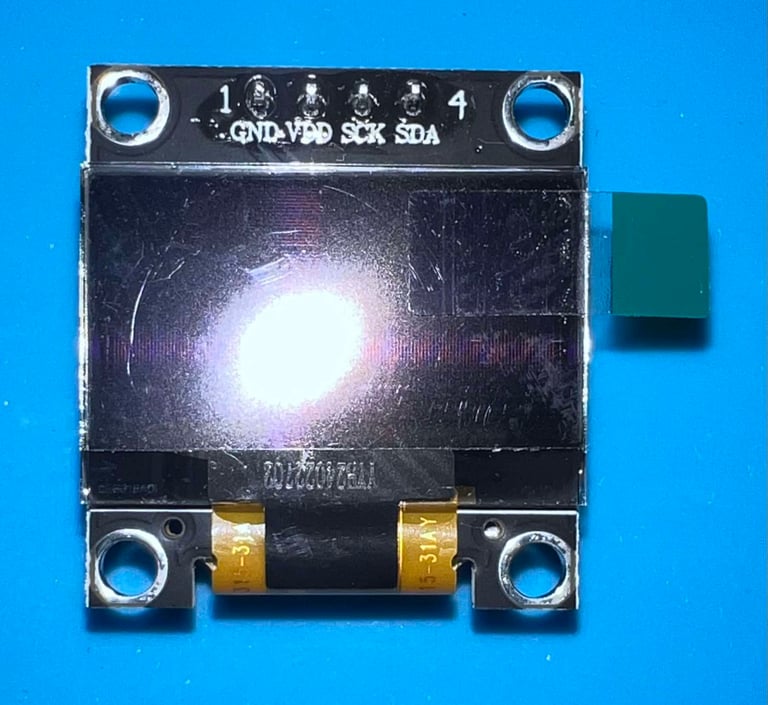
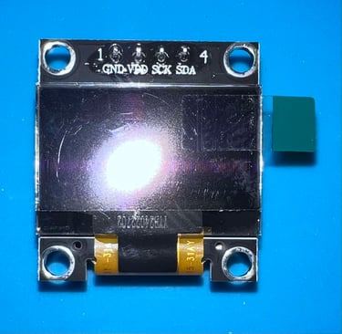
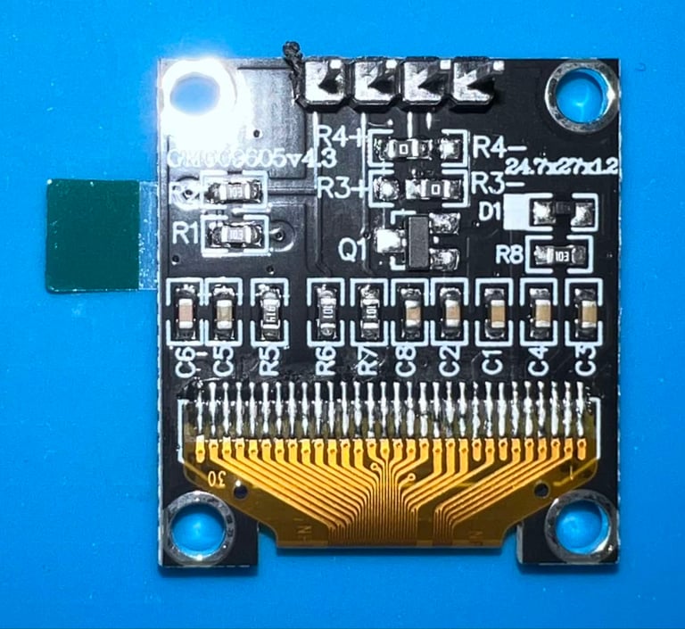

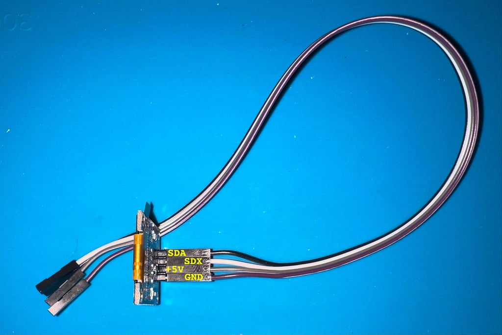
Luckily, the OLED display module is pre-assembled so the only thing missing is to add the four DuPont connectors.
User port connector and parallel cable
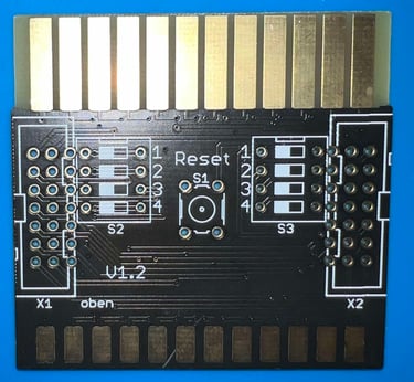
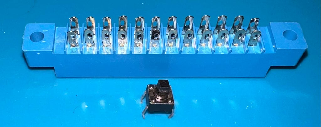
Assembling the User Port connector
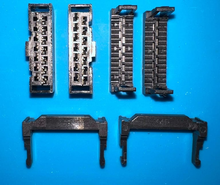
A connector, mounted on a special PCB, is used to to connect to the User Port. The assembly kit consists of:
1 x special User Port connector PCB (Version 1.2 designed by Thomas Linke)
1 x 24 pin female connector
1 x 14 pin header
1 x tactile push button
Below are pictures of the parts before assembly.

Before the 24 pin connector is soldered to the PCB the pins are carefully bent towards the middle of the connector. This will make it easier to solder the connector to the PCB.

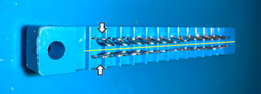
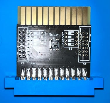
The connector is soldered to the PCB as can be seen in the pictures below (from the top- and bottom side).
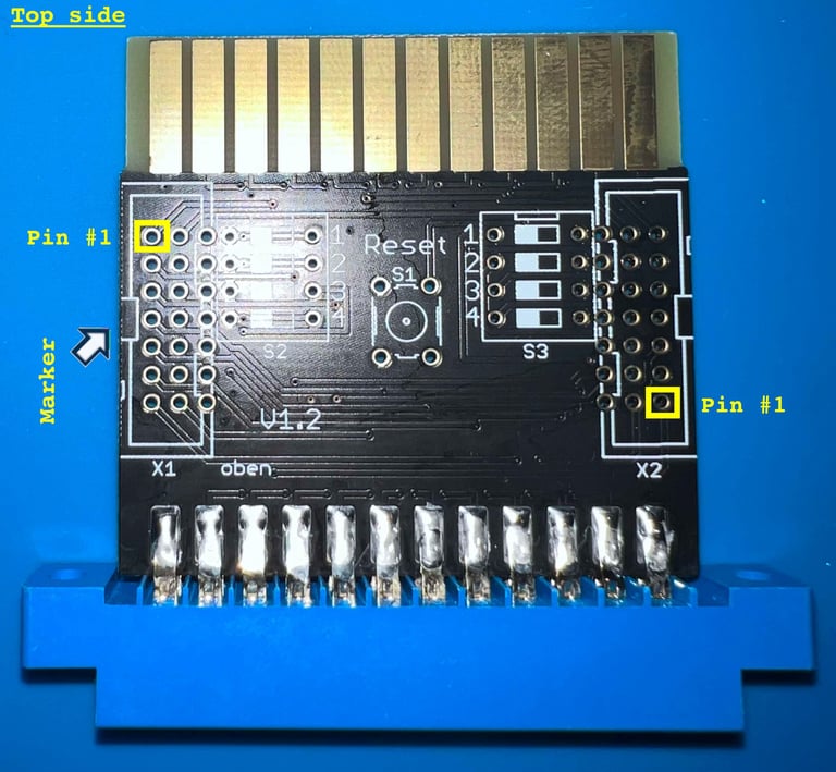
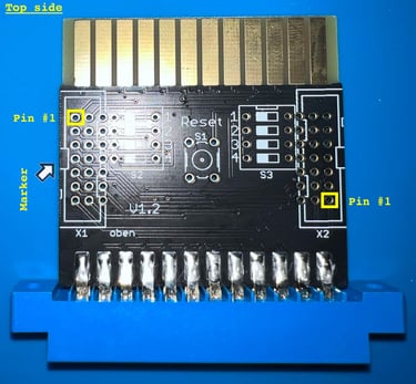
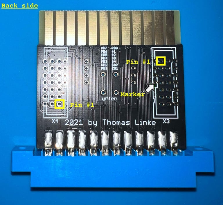
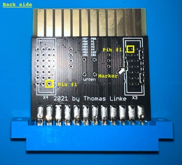
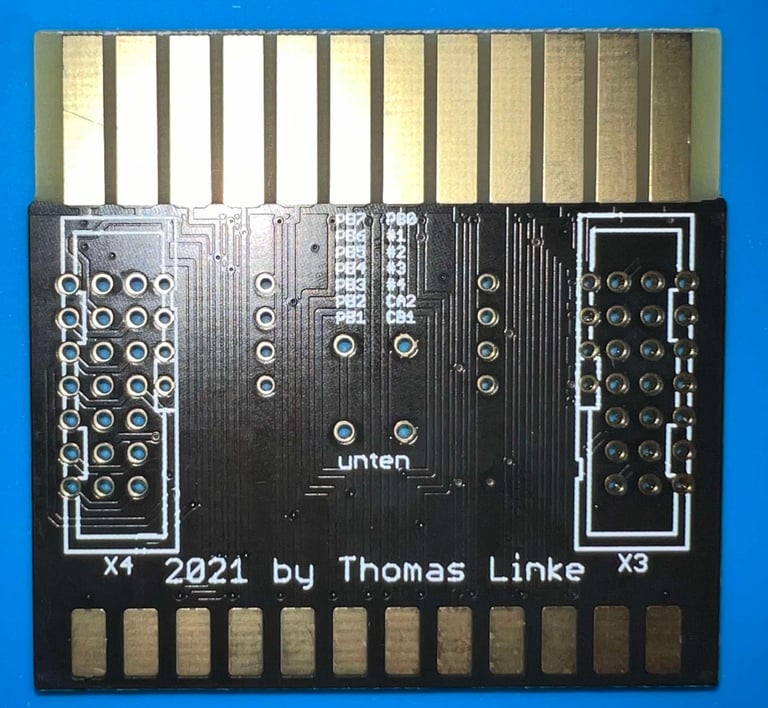
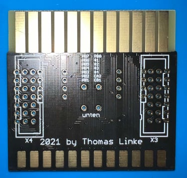
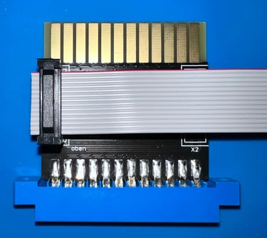
Note that the User Port PCB is a very versatile board - you can choose to have the 14 pin header at four different places (X1, X2, X3 and X4). Two of these, X1 and X2, are on the top side of the PCB while X3 and X4 are on the bottom side. The silkscreen shows where the marker on the connector must be for the position for pin #1 to be correct. Note that the marker is the small protruding rectangle found on one of the sides on the cable connector.
Next, the 14 pin header is soldered to the PCB in position "X1". Note that pin #1 is the top left pin (see picture above).

The tactile push button (RESET) is soldered in position "S1".
In the picture below you can see the complete PCB with the 24-pin connector, 14-pin header and push button installed. Note that the remaining pin holes are not used (they are for special usage - not required for normal MeGALoDOS operation).

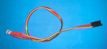
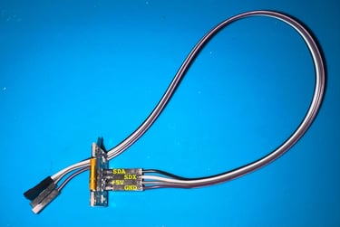
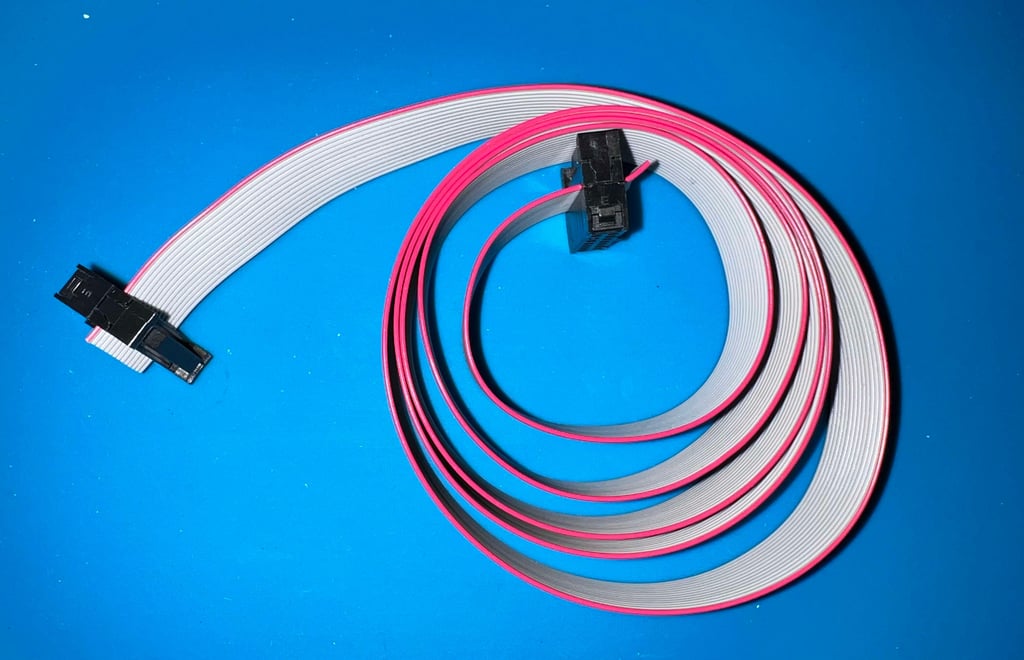
Assembling the parallel cable
Say goodbye to only transferring data old bit-by-bit using the serial cable. Say hello to the parallel cable transferring eight bits at the time! The MeGALoDOS support both parallel and serial speeders.
Assembling the parallel cable is quite straightforward, but it is wise to make notice of which pin is "Pin#1" on both the User Port connector PCB and the VIA Parallel adapter. The parallel cable must make a 1:1 connection between these pins. In the pictures above, describing both the User Port and VIA Parallel adapter PCB.
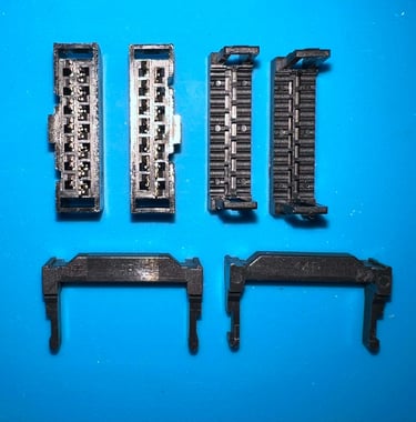
The assembly kit consists of:
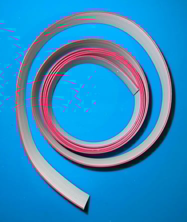
1 x ribbon cable (14 conductors)
2 x 14 pin ribbon cable connector kit
Below are pictures of the parts before assembly.

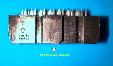
A small note on the 14-pin connector. To make sure you mount the cable to the connector the right way there are two things to notice (see picture below also):
There is a small triangle symbol indicating the position of PIN #1
There is a protruding rectangular marker on one of the sides. This needs to be aligned with the silkscreen on the User Port PCB.
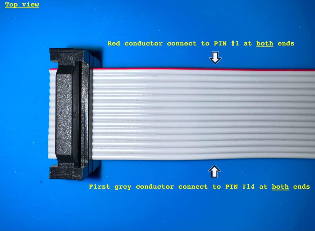

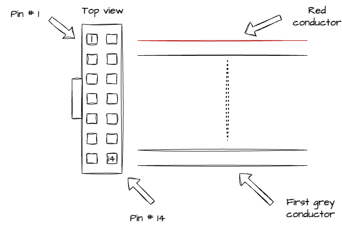
There are probably different ways to attach the ribbon cable to the connector, but in the schematic below I have described how I did it. Seen from te top of the connector the pin #1 i set to be top left corner. With this configuration the small protruding rectangle shape is on the left hand side. The ribbon cable, with the red conductor on the top, is then munted to the connector.

To mount the connector to the ribbon cable a small vice is used. The cable is carefully aligned in the connector, and then the vice is carefully tightened until all connectors are firmly connected. Below is a picture of the completely assembled parallel cable.

Below are some pictures showing how the cable is attached to the User Port.
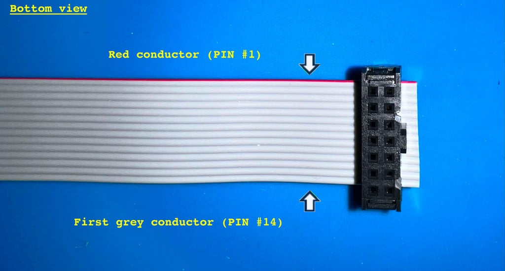
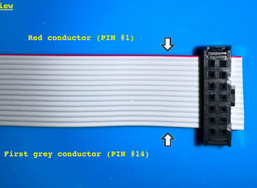
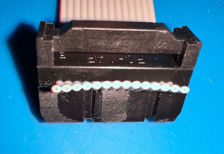
When assembling the ribbon cable and the 14 pin end connector the red coloured conductor is chosen to be connecting pin #1, and the first grey conductor is connected to pin #14. This is important to keep in mind when the cable is mounted eventually on the User Port- and VIA Parallell PCB. Pay attention the markings on the silkscreen on these PCBs. Below are pictures from both top- and bottom view.

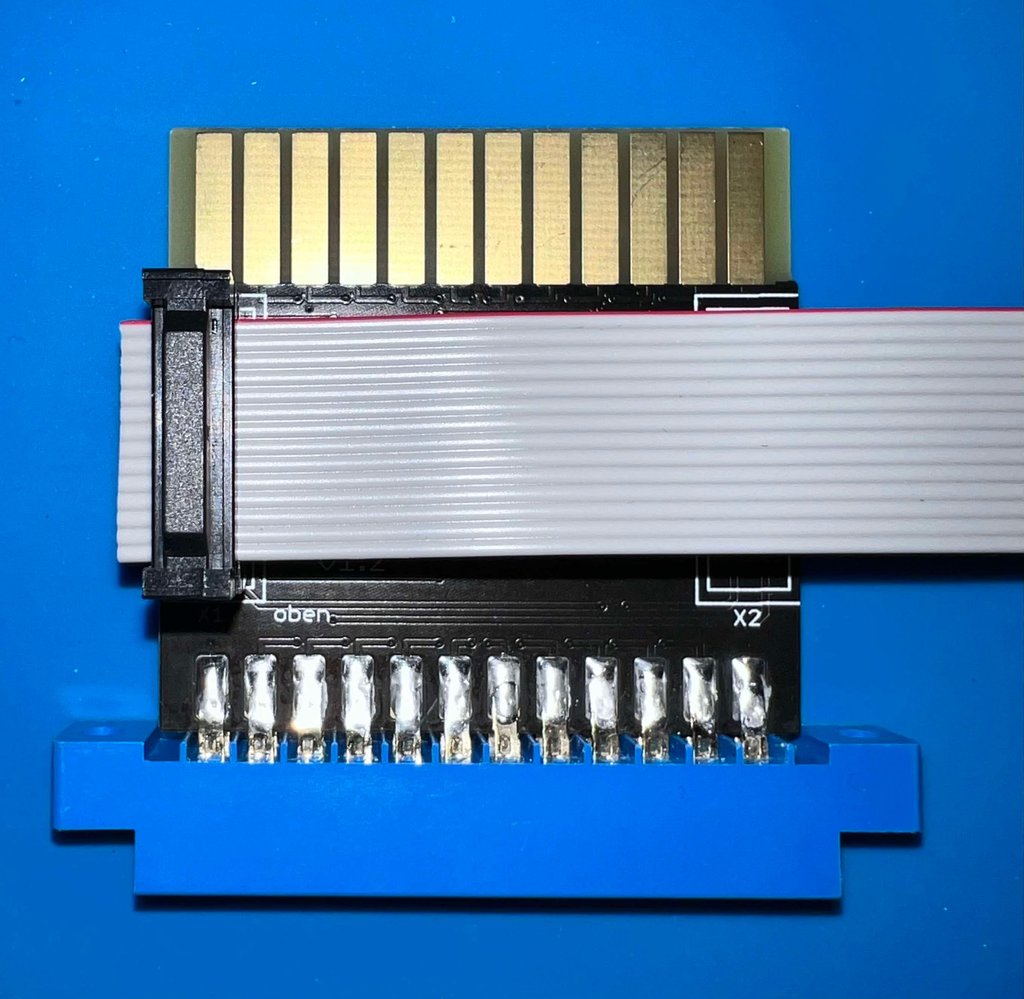
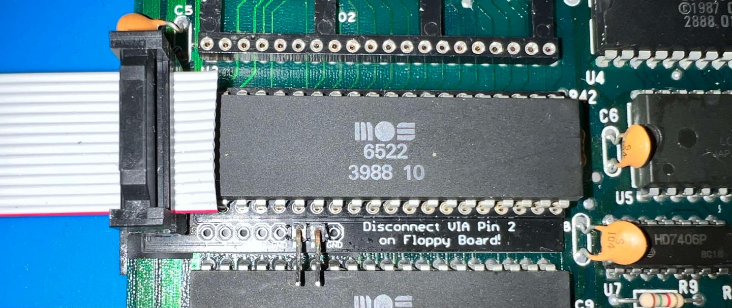
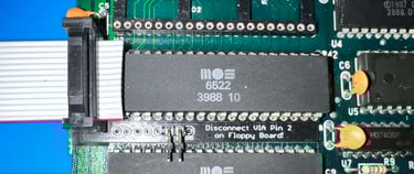
To get the 14 pin connector to fit on the VIA parallel adapter a little trick is used. The protruding rectangular marker is slightly too big to fit in between the VIA IC and the 14 pin header. To compensate for this the marker is just filed/sanded away, and a small sticker is installed instead of the marker. See pictures below.

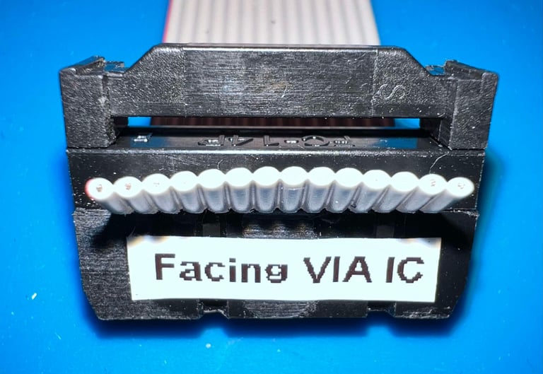
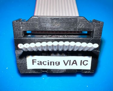
Below is a picture of the cable attached to the VIA parallel adapter. The sticker saying "Facing VIA IC" is... yes... that is correct! Facing the VIA IC :-)!
Troubleshooting
The first attempt of installing the MeGALoDOS in the 1541-II drive is not a success unfortunately. This are the symptoms when the module is installed:
The rotary encoder and display operates flawlessly. You can choose you any of the pre-installed DOS using the rotary encoder switch.
When choosing any of the DOS versions either of the following happens:
The red LED is constantly switched on an the disk is spinning continuously
The red LED is flashing slowly about once every second
The red LED is flashing rapidly a few times, then pause and then repeats
The red LED is switched off about 2 seconds after power-on (but the drive does not respond to commands issued by the Commodore 64)
With some FANTASTIC help from the maker of MeGALoDOS the fault is identified to be:
A faulty RAM chip on the MeGALoDOS board
Now, how could this happen? Not sure. These RAM ICs are quire robust, but some hypothesis could be:
Damage by ESD when assembled
Overvoltage from a poor power supply
Short circuit
None of these are obvious culprits; both ESD wrist strap and -mat were used, PSU measured to be <5.2 VDC and <12.2 VDC and no short circuits were found that should cause such damage.
Nevertheless, with magnificent help from the designer of MeGALoDOS the board is repaired (RAM replaced).
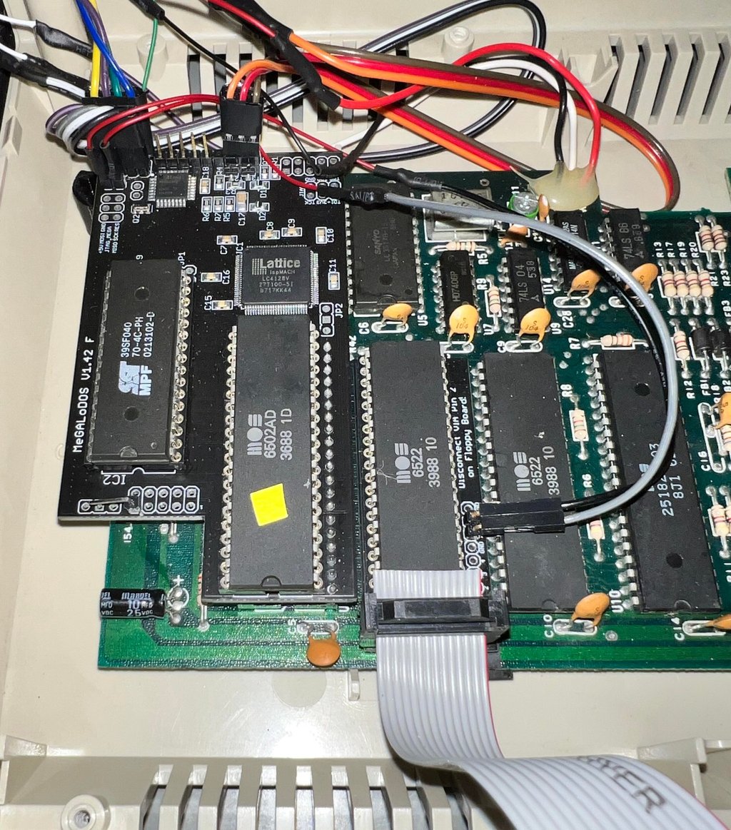
Installation and next steps
The MeGALoDOS modules are installed in a 1541-II drive mainboard and some quick tests are made. Everything seems to be working as it should! The complete installation of the MeGALoDOS modules in the 1541-II drive can be found in the description of the refurbish of the drive.
Banner picture credits: sebos (forum64.de)